


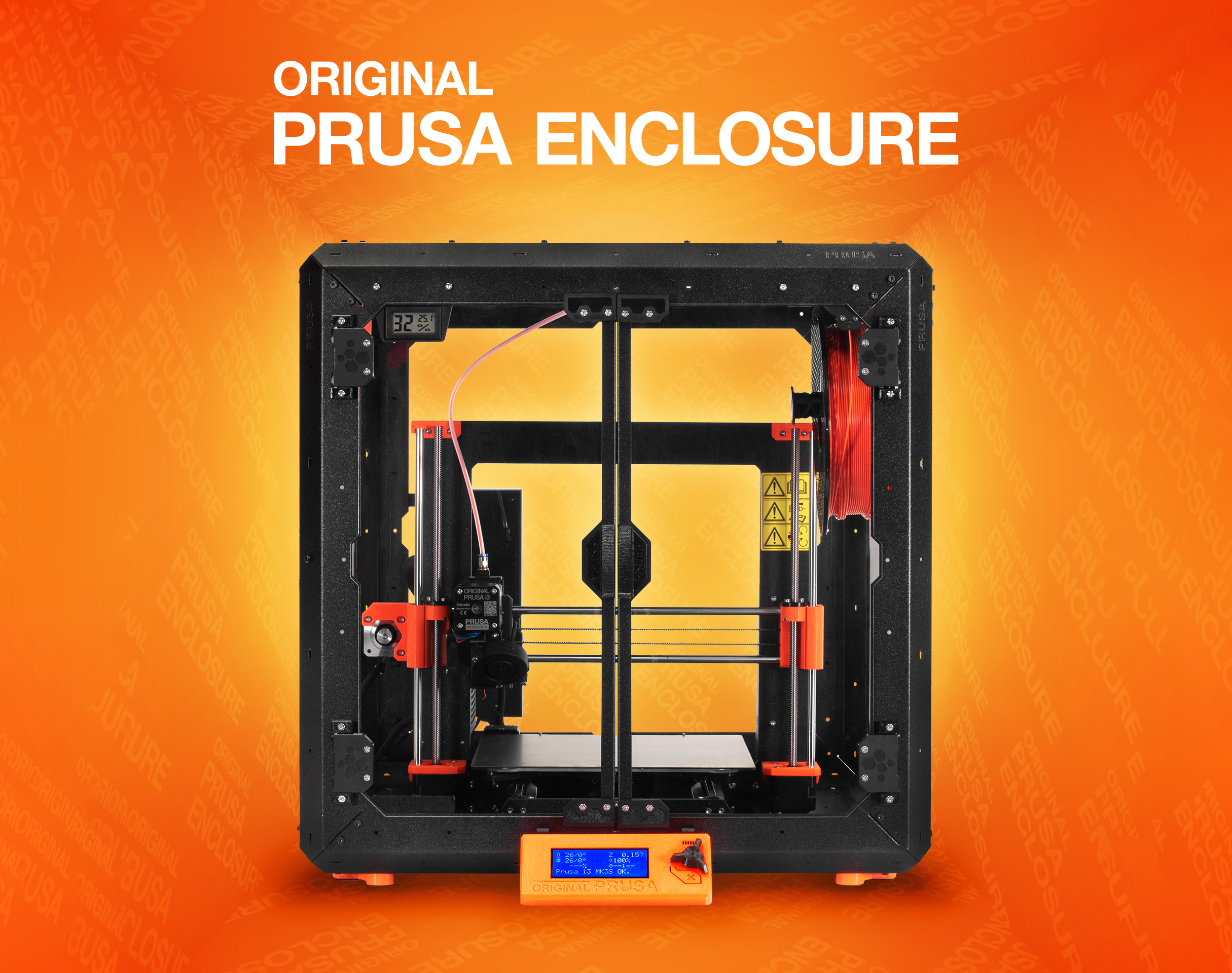
Our first 3D printer enclosure became incredibly popular – and naturally, once we released our new Multi Material Upgrade 2.0 and 2S, people started asking us for an updated enclosure that would accomodate the Original Prusa i3 MK3S (and 2.5S) 3D printer along with the MMU2S unit. So, here it is – and it’s better than ever!
If you’re looking for a high-end enclosure that’s expandable with official and user-made add-ons, we created our own solution. You can learn all about it in the Original Prusa Enclosure release article and order it from our eshop.
If you have no experience with 3D printer enclosures, let us give you a quick tour of their benefits:
- Stable printing conditions – sudden bursts of cold air and draft in general can negatively impact the printing process. The enclosure will ensure a higher, stable temperature around the 3D printer. Significant differences between the temperatures in the room and on the heatbed can have undesired effects – objects detaching from the print bed, layer warping and poor layer adhesion especially when printing with ABS and ASA
- Less noticeable odors – certain materials can produce somewhat unpleasant smells. The enclosure will contain these vapors during the print. Once the job is finished, you can open the enclosure e.g. next to an open window to quickly vent the unwanted odors
- Noise reduction – if you, for some reason, still think the MK3S is noisy, you can isolate the printer in the box to further reduce the noise. This can be useful e.g. if you want to place the machine directly next to your desk.
- Dust reduction – the enclosure will help to decrease the amount of dust on the bearings and rods of the machine
- Compact setup – The MK2.5S/3S 3D printer, MMU2 unit, filament buffer, five spools and spoolholders, PTFE tubes… there’s a lot of things around the printer. Everything will be neatly organized.
- It’s a cool DIY project 🙂
However, before we begin, we would like to mention that the enclosure doesn’t actually benefit print quality when printing with PLA – actually, if you decide to print with PLA (e.g. Prusament), we highly recommend keeping the front door partially open to give the nozzle (or more specifically – the heatbreak) enough airflow for sufficient cooling. High temperatures combined with PLA materials can lead to partially clogged nozzle. You will see the real benefit of the enclosure when printing with ABS and ASA. Increasing the temperature around the printer and creating a stable environment inside the box will improve the bed adhesion and prevent layer warping. Either way, you will certainly appreciate the compact configuration of all the components.
Our IKEA Lack enclosure became incredibly popular (nearly 150,000 downloads of printed parts!), mainly because it’s an elegant and cost-effective solution. Plus, the size of the Lack table is pretty much ideal for our 3D printers. While we’re really proud that we made something so popular, it also made the starting point for the new version more difficult. What if you already made an enclosure? What if you already paid for the acrylic panels? We don’t want you to start from scratch. Instead, we decided to modify the original concept and improve it. We’re keeping the acrylic panel dimensions, and if you didn’t damage the Lack tables too much, you should be able to re-use them. All printed parts are different, though. On the other hand, the enclosure comes with a number of useful new features, such as a semi-automatic locking mechanism of the lid, magnetic hinges and a small compartment for various tools.
The primary goal was to design the enclosure in such a way that anyone will be able to build it at home, using printed parts, regular fasteners and easily accessible materials in general. Non-standard elements are kept to a bare minimum.
So, those were the challenges we had to overcome. Now for the benefits of our solution:
- We kept the original dimensions for acrylic panels (440×440 mm). If you have already built the previous version of the enclosure, you can re-use your current acrylic panels
- We have integrated the filament buffer (part of the MMU2S upgrade) to prevent filament strands from tangling during retractions
- The enclosure can be placed in the corner or between two pieces of furniture – only access to the front and the top is required
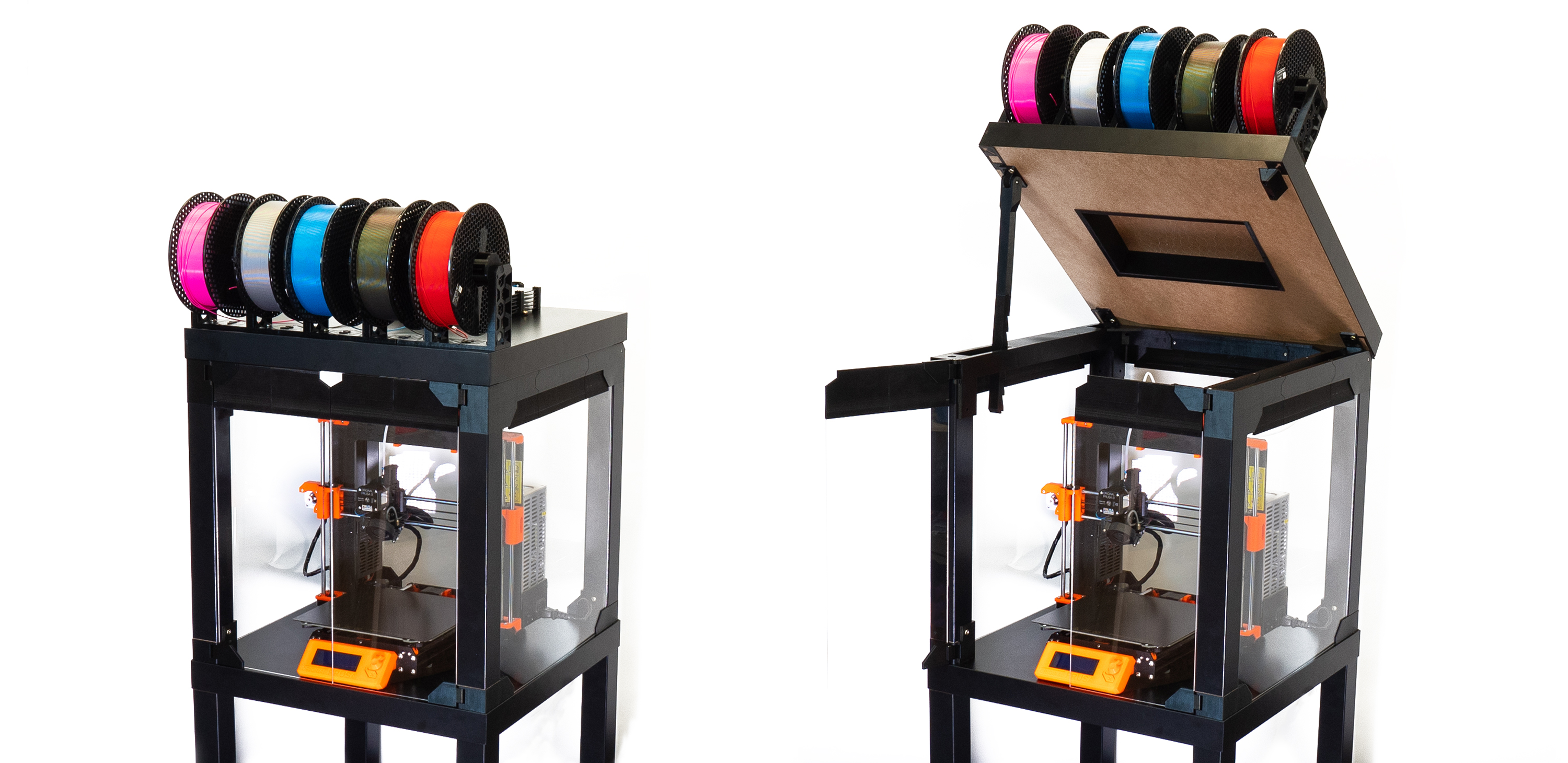
- The MMU2S unit is easily accessible by opening the top cover
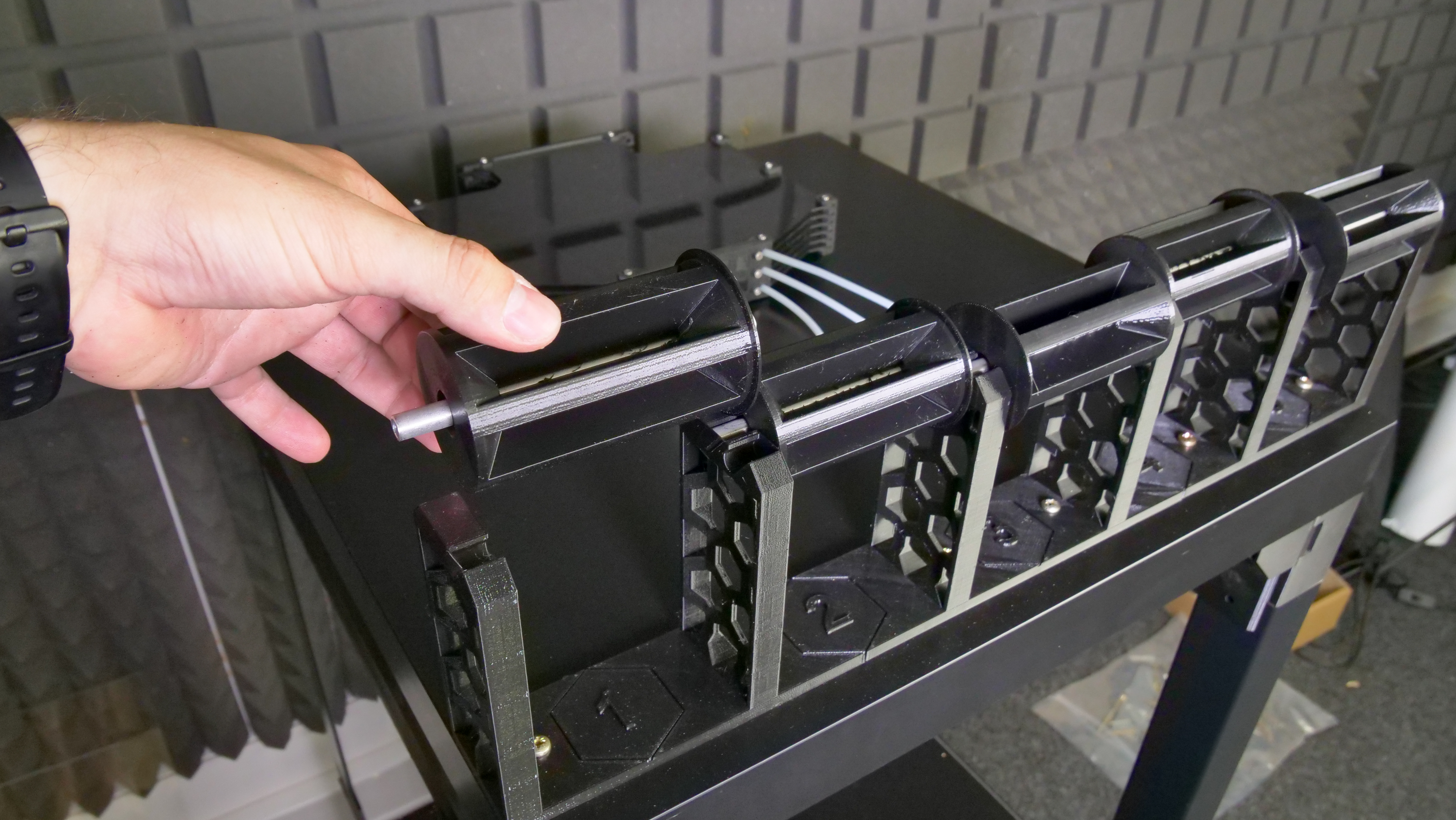
- There are 5 spoolholders on the top of the enclosure, which can accomodate 5 filament spools – each up to 89 mm wide
- Re-used parts from the MMU2S package, such as spoolholder shafts
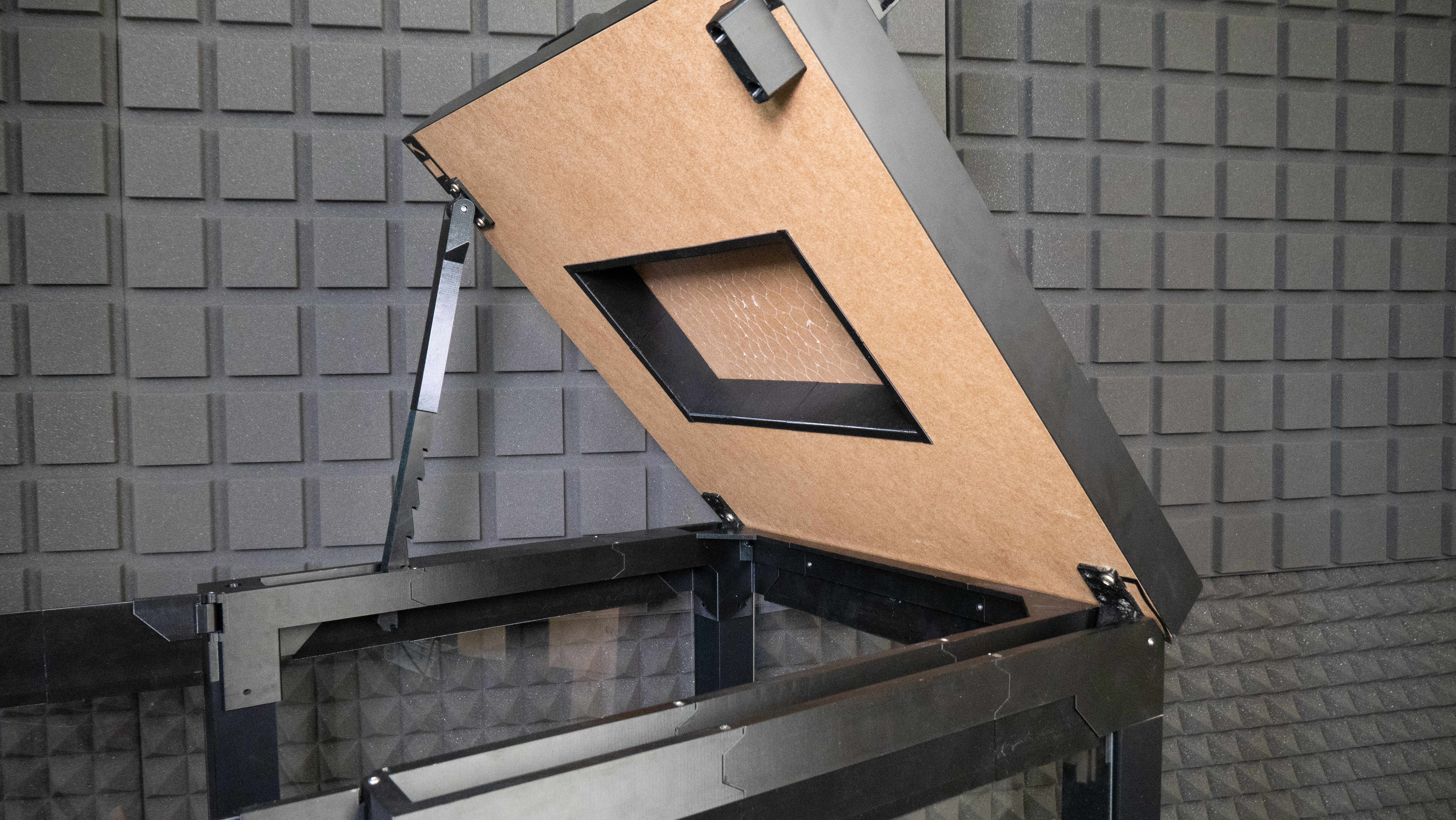
- The top cover can be opened easily – there’s a semi-automatic locking mechanism that holds the cover open. To close it, just lift the cover slightly and pull the locking arm towards you, then close the cover
- Enough room for the orange PTFE tube leading from the MMU2S unit to the extruder
- Robust hinges with integrated magnets that hold the front door closed
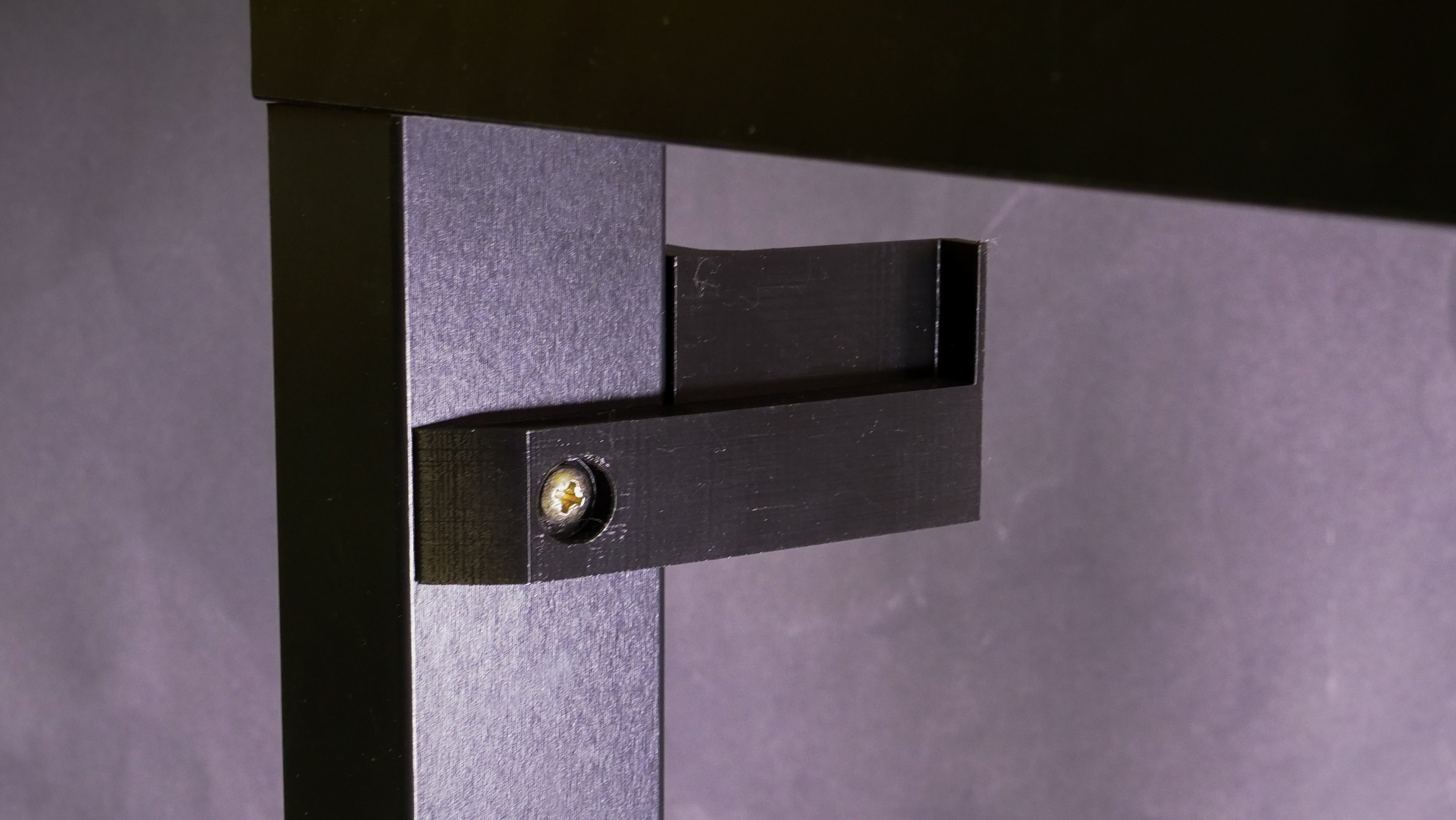
- The supporting locking mechanism arm is hidden in the frame when the cover is closed
- A small storage compartment in the frame – useful for storing small tools
What will you need?
Printed parts:
- 1× Printed parts set or in case of 1/8 inches (3.175 mm) thickness acrylic sheets replace some of them by this prints
- 1× 60-degree mounting cover for heatbed cables
Basic parts
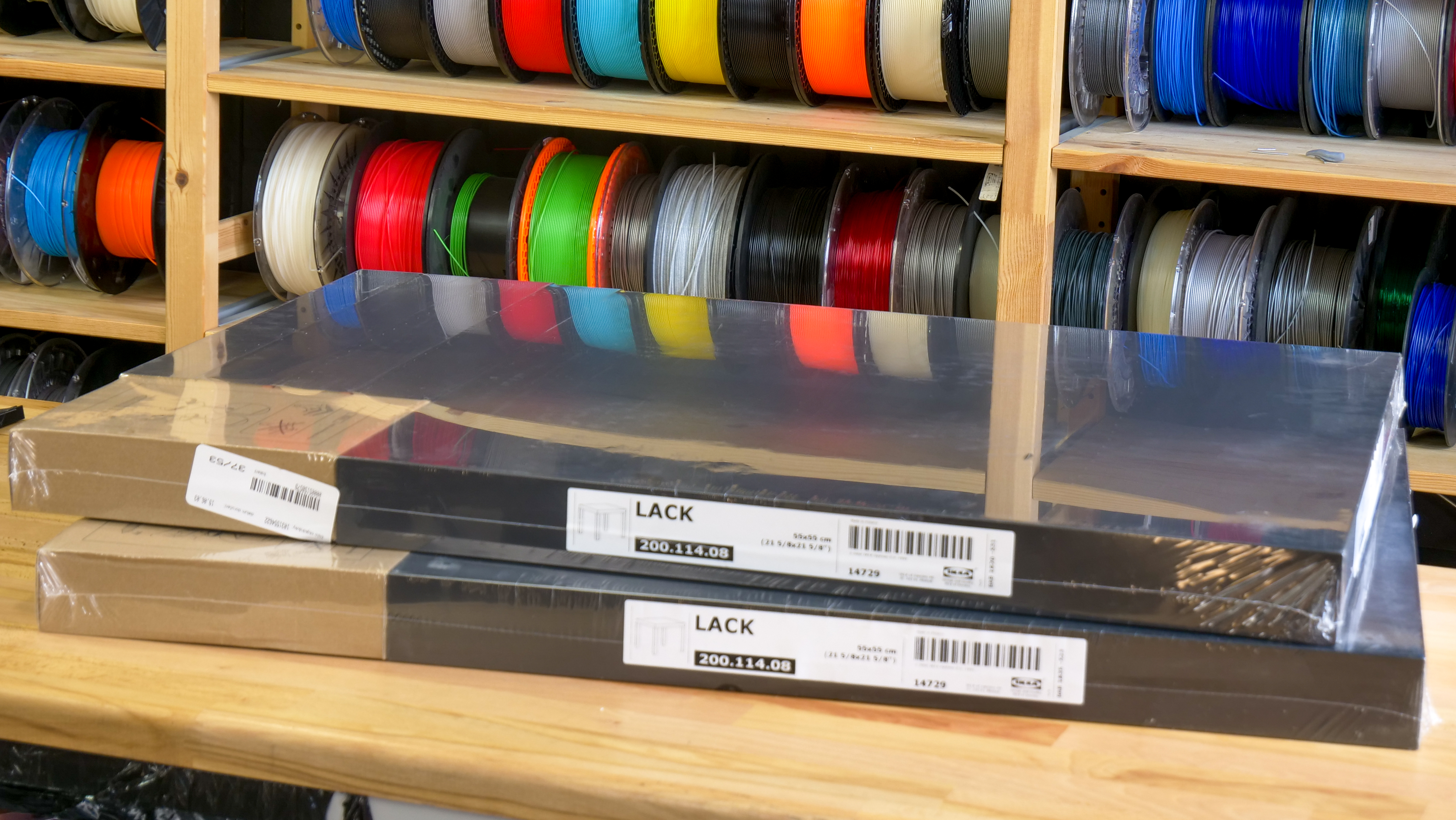
- 2× IKEA Lack table
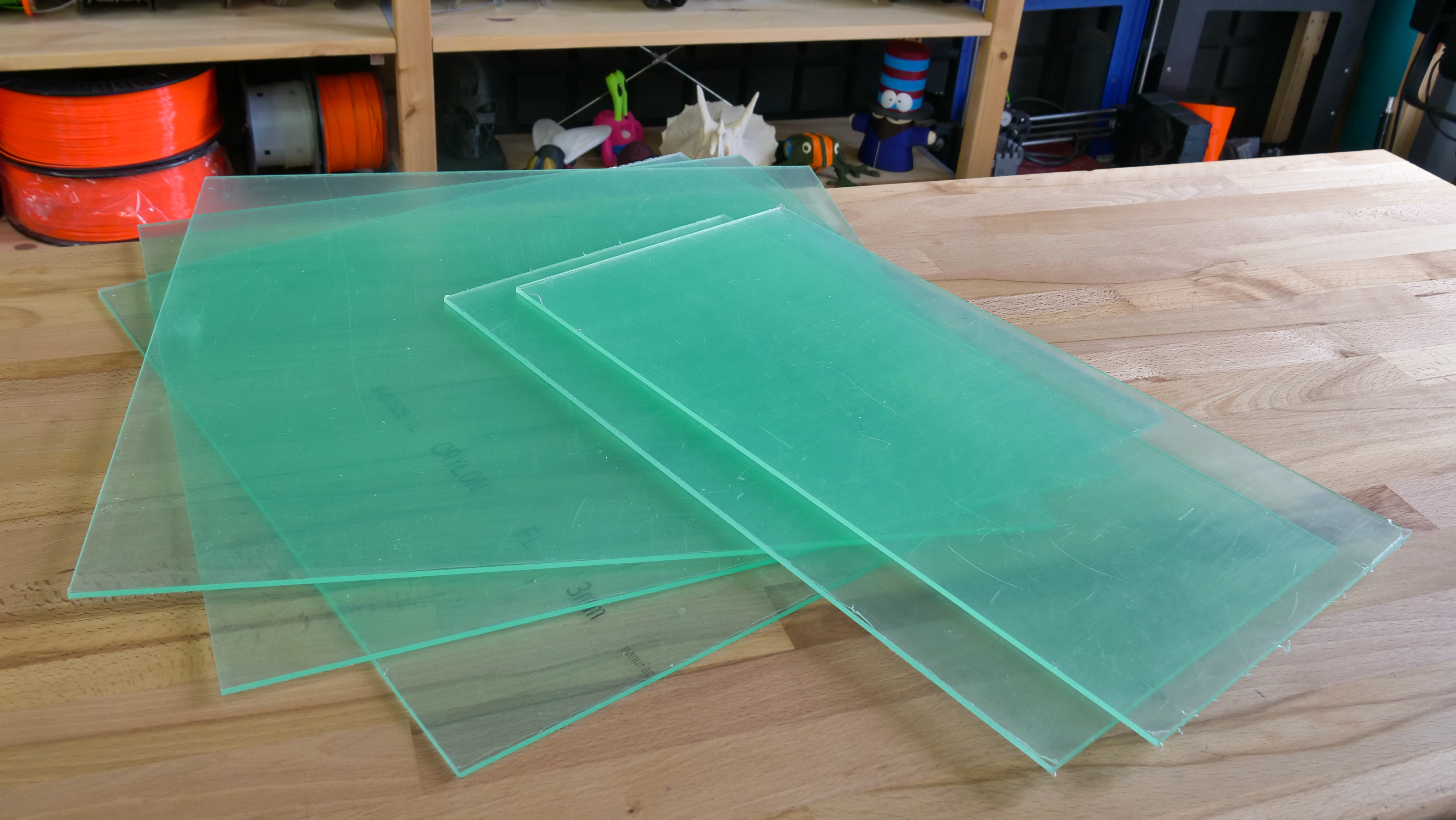
- 3× Clear acrylic sheet 440×440 mm, 3 mm thickness – reused from enclosure V1. If you don’t have these sheets yet, you can order a larger size that doesn’t need 3D-printed extensions, the dimensions are 440×473 mm, 3 mm thickness.
- 2× Clear acrylic sheet 220×440 mm, 3 mm thickness – reused from enclosure V1. If you’re ordering new sheets, you can go for a larger size that doesn’t need 3D-printed extensions. The dimensions are 220×505 mm, 3 mm thickness
Side note: throughout this guide, we will keep using the term “clear acrylic sheet”, but Plexiglass/Plexi glass/Plexiglas can be used without a problem, depending on your preferences.
Fasteners
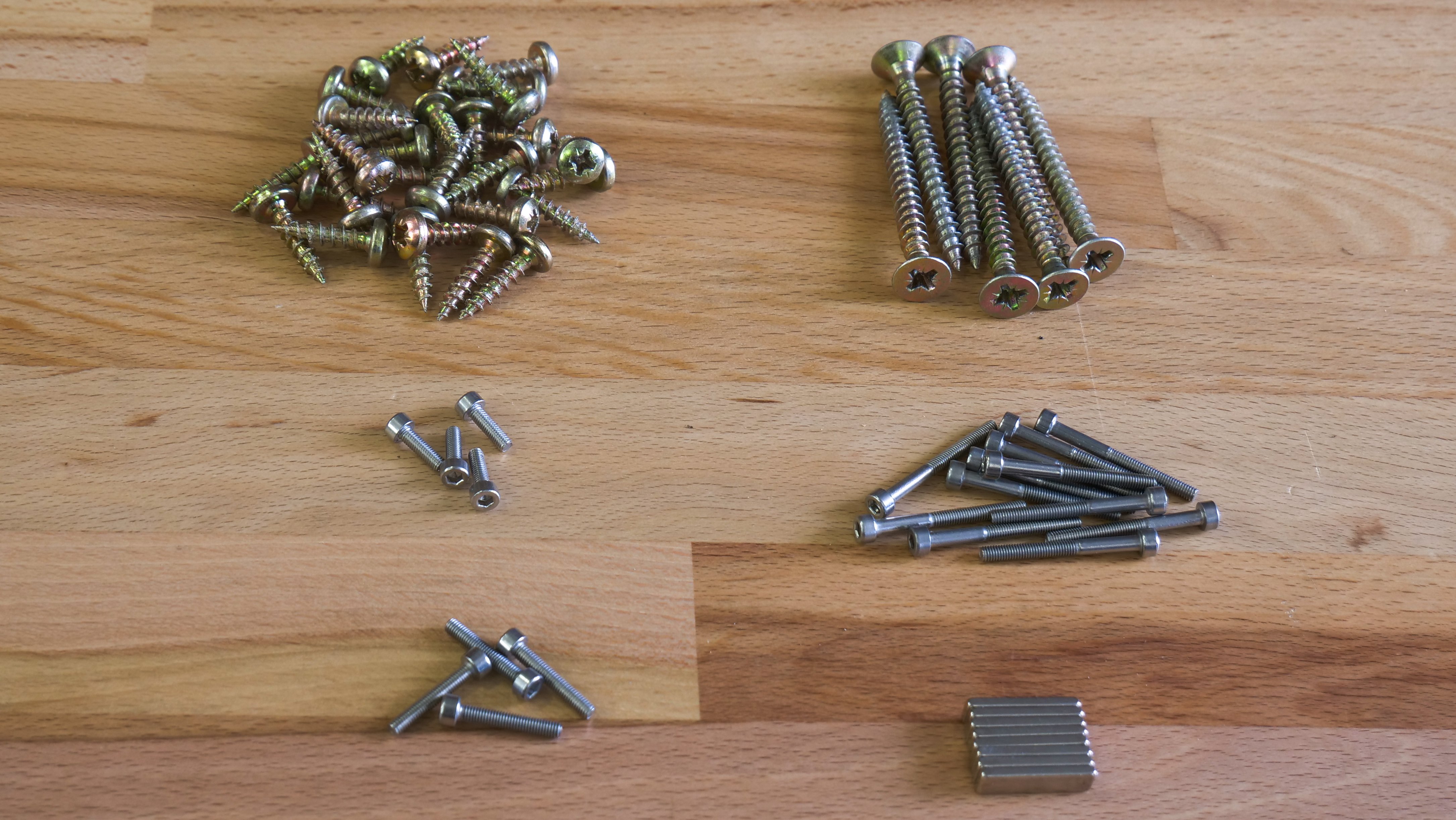
- 35× pan head screw, 5×20 mm
- 4× screw 6×50 mm
- 4× screw 6×30 mm
- 12× screw M3×30
- 4× screw M3×10
- 4× screw M3×18
- 8× neodymium magnet, 20×6×2 mm
In addition, if you want to place PSU outside the enclosure:
- Silver PSU: 3× pan head screw 5×20, 1× screw 3×10 mm, 2× M4 nut
- Black PSU: 3× pan head screw 5×20, 1× screw 3×10 mm, 2× screw M3×12, 2x M3 nut
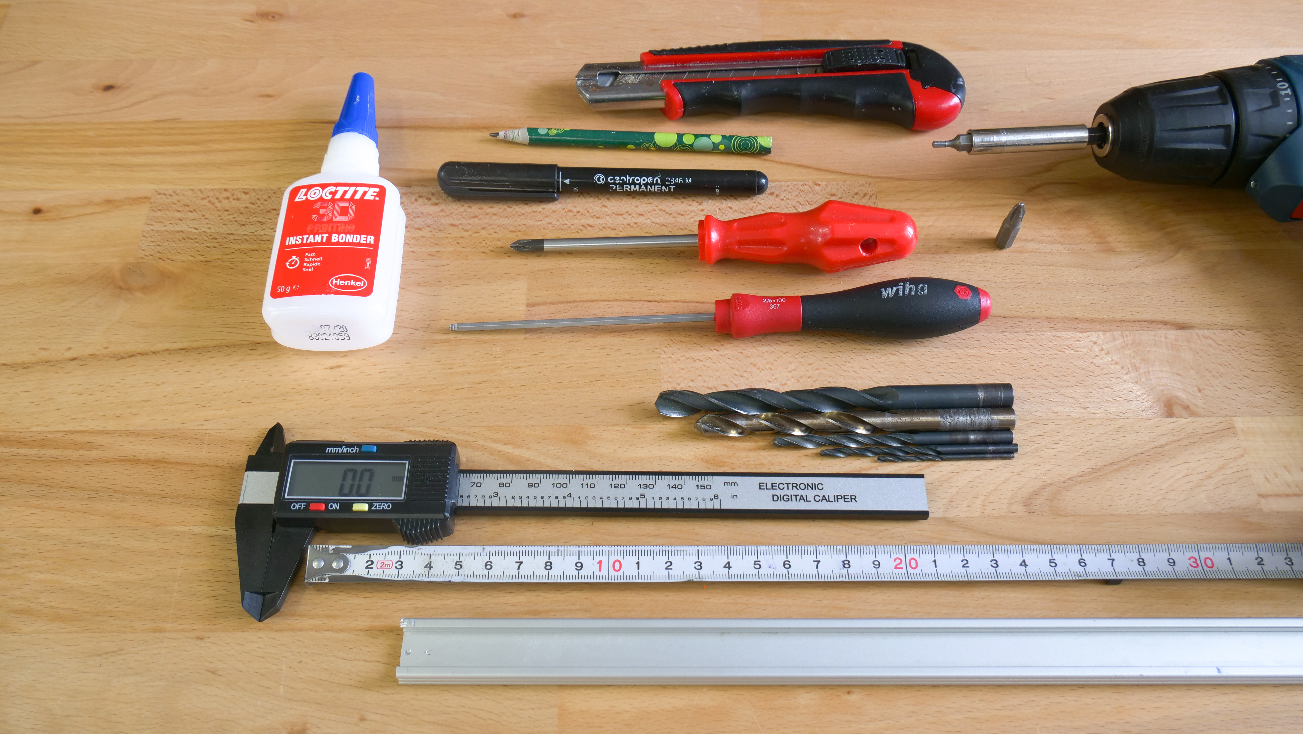
Tools
- Philips screwdriver
- Allen key – 2,5mm
- Superglue / Locktite
- Drill + wood drill bits ø 2 mm, 5 mm, 8 mm and 10 mm
- Tape measure
- Snap-off knife
- Ruler
- Pencil or marker
In addition, if you want to place the PSU outside the enclosure:
- wood drill bit ø 12 mm
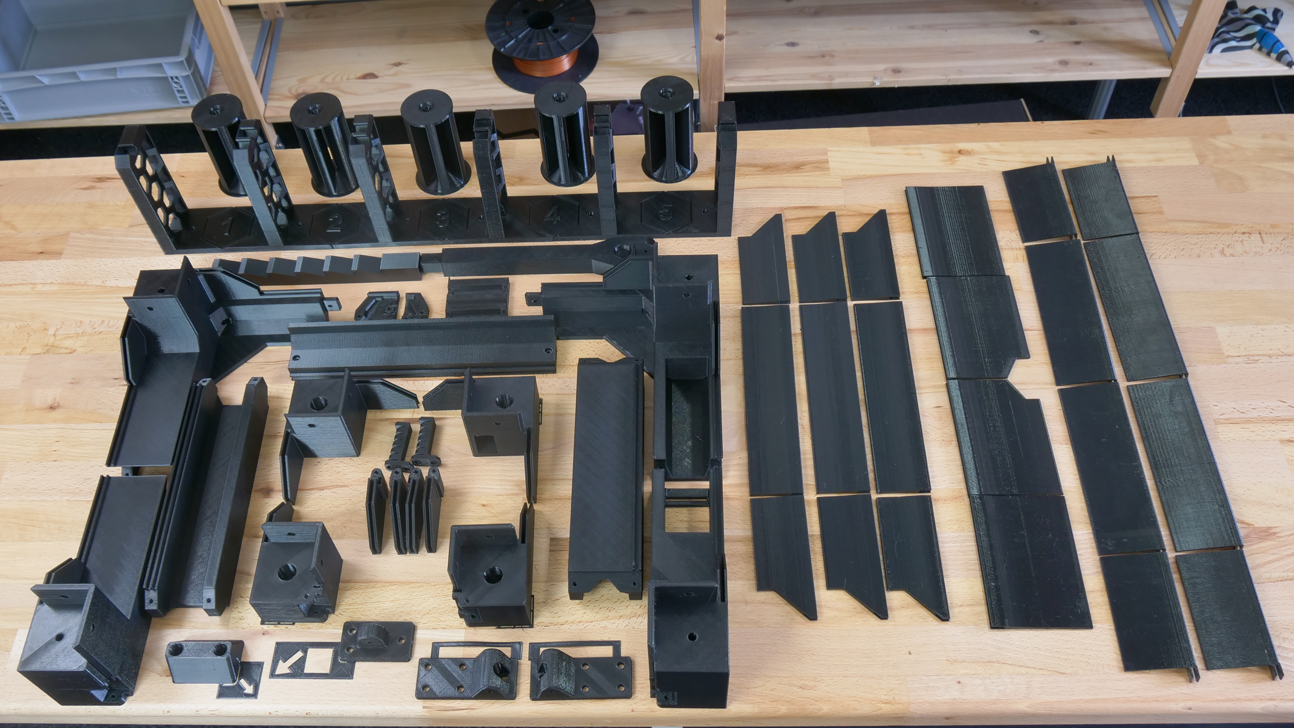
Printing the plastic parts
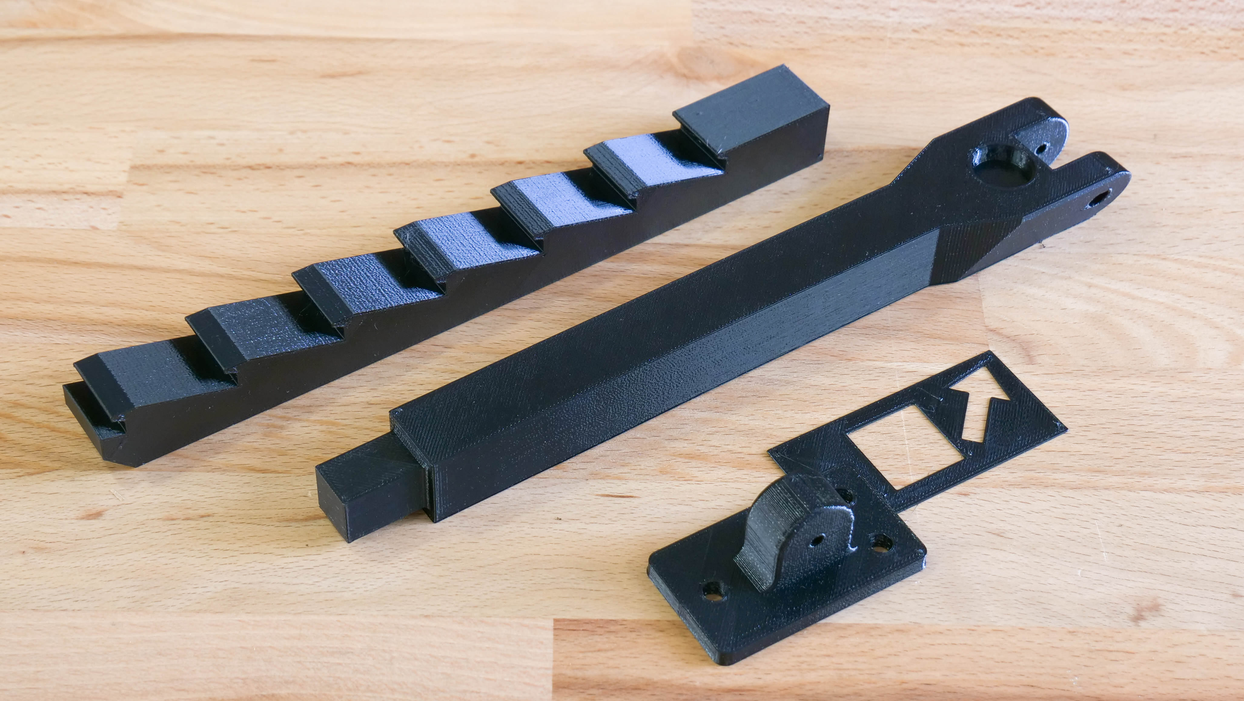
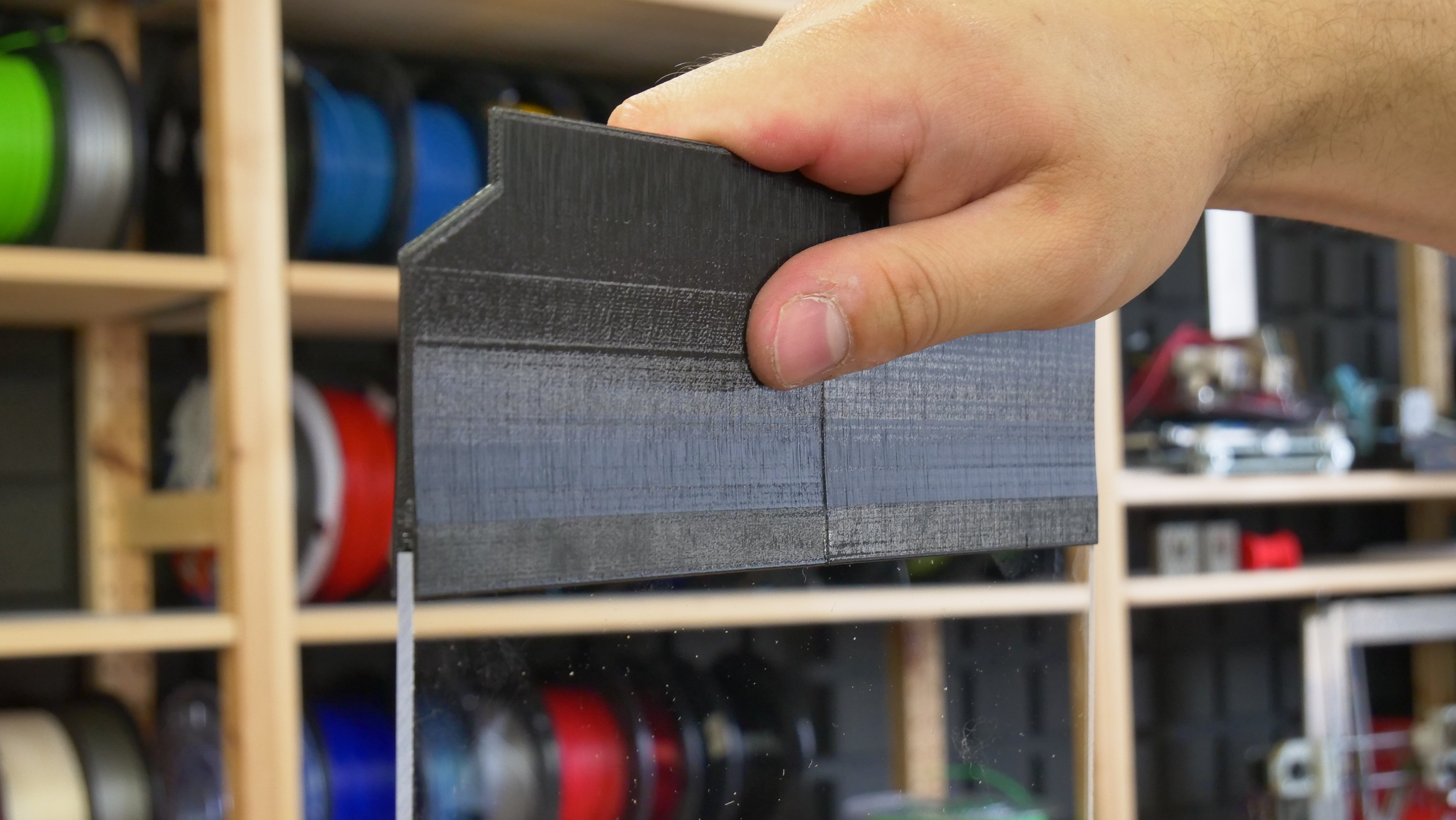
We recommend printing the plastic parts with PETG filament – e.g. Prusament PETG Jet Black. You can use our pre-made G-codes, which are already tested and, of course, sliced with the optimal settings. Or download the .3MF files from the same link and slice them yourselves. Several parts come with a mounting bracket, that will help you position these components and secure them in place. Please, do not remove the mounting brackets before you secure the parts in place. However, do not forget to remove the support material, so the parts can be put together.
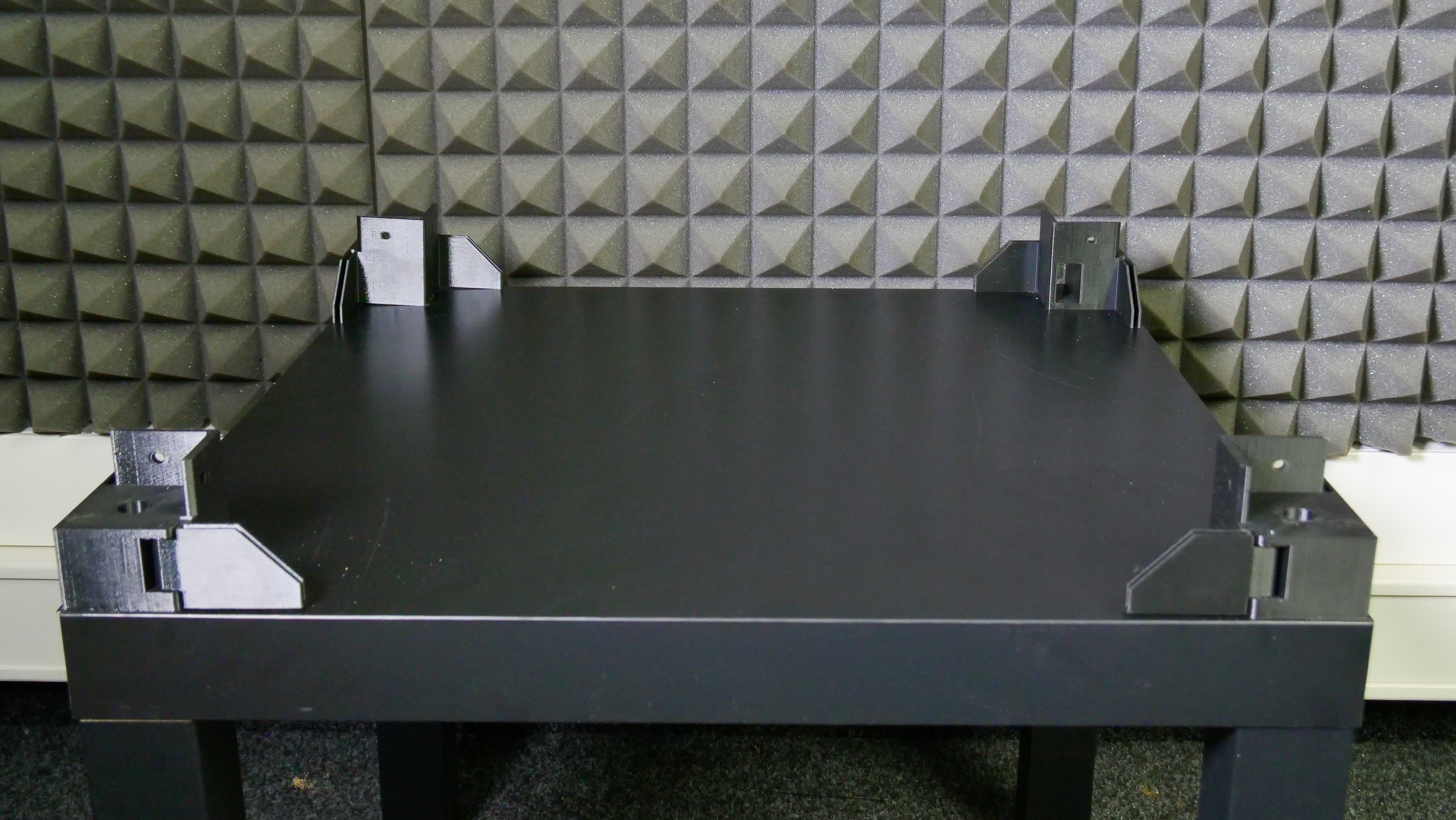
Building the box – lower table
The box usually consists of two IKEA Lack tables. Even though it’s possible to place the whole setup onto another Lack table, it will make access to the MMU2S unit and the buffer more difficult.
List of plastic parts required for this step:

Placing the Power supply – UPDATE
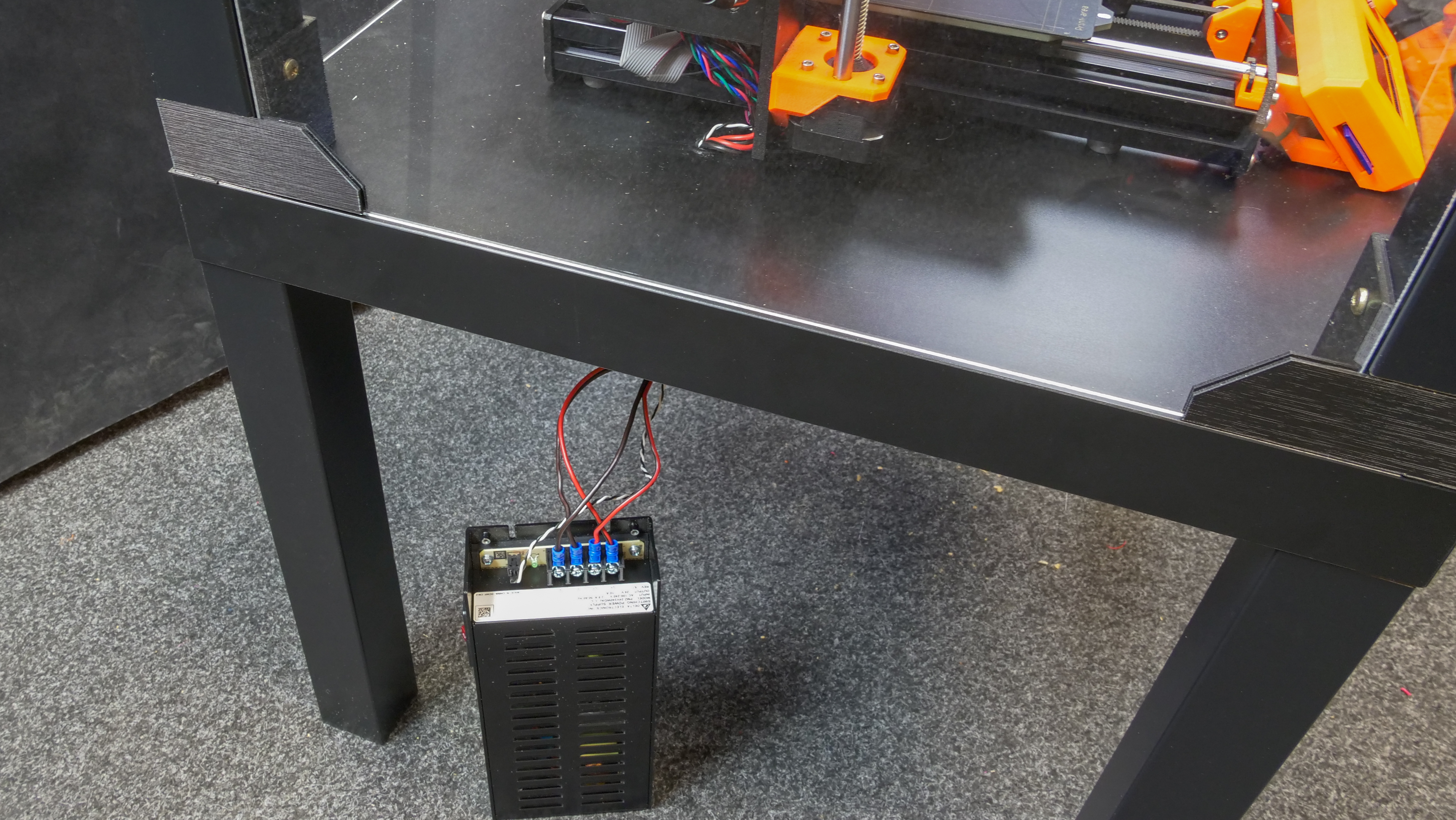
You need to decide whether to remove the power supply from the printer (outside the enclosure) or leave it on the printer (inside the enclosure), depending on the intended use of the machine. If you do not plan to run long prints from materials that require higher temperatures (ASA, ABS, PETG), you can leave the PSU on the printer and leave the front door ajar when printing. However, if you print at higher temperatures, the heated bed warms the air inside the enclosure to about 40°C (when the ambient temperature is 27 °C). In this case, it is advisable to place the PSU outside the enclosure. Long-term use of the PSU at high temperatures (above 45°C) may shorten its life. On the other hand, leaving the PSU on the printer will make it easier to remove the printer from the enclosure. Have you decided to keep the PSU inside the enclosure? Skip the next assembly step. Otherwise, follow the instructions below.
The assembly procedure and printed parts vary depending on the PSU type on your printer.
List of plastic parts for this step:
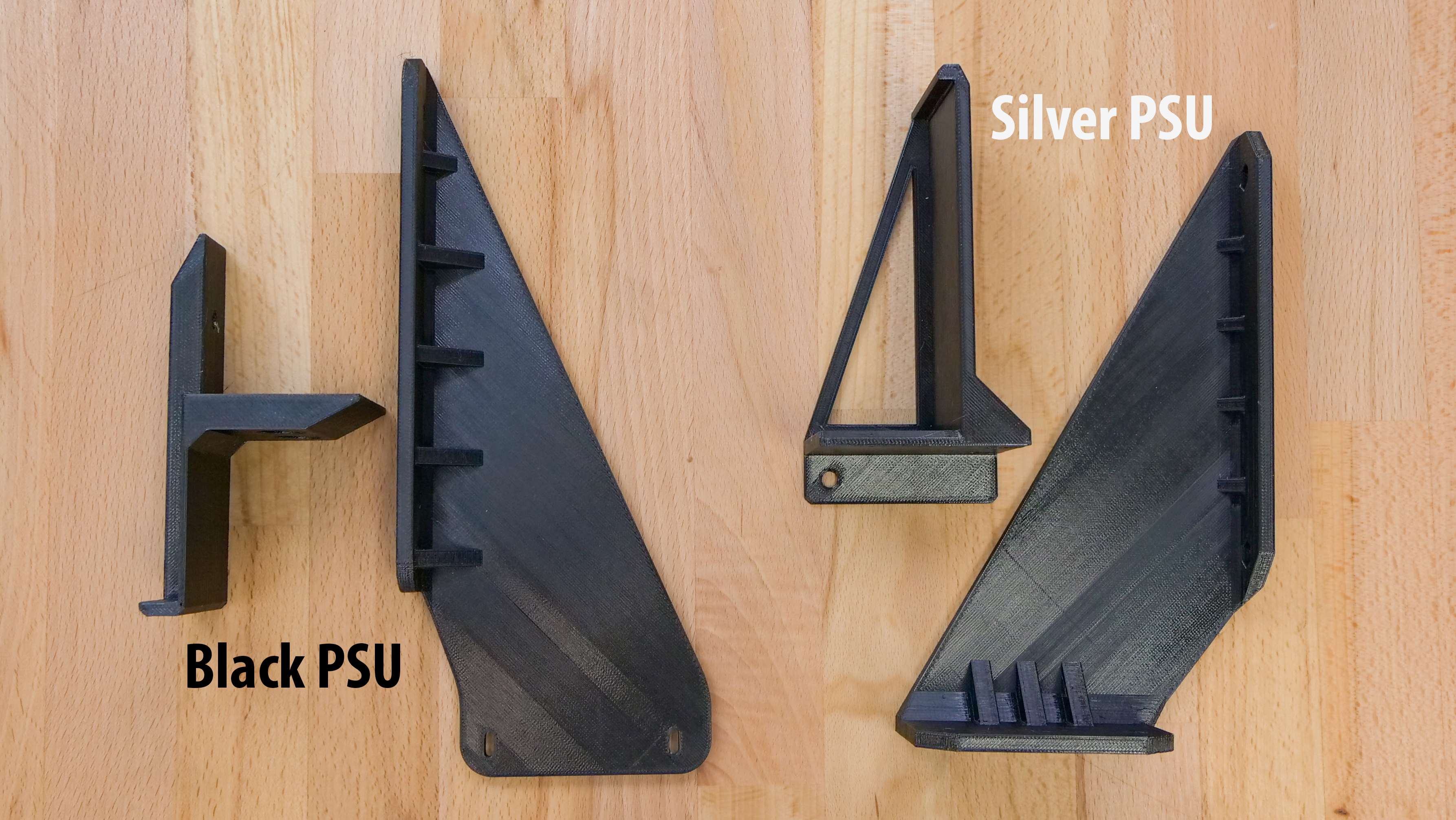
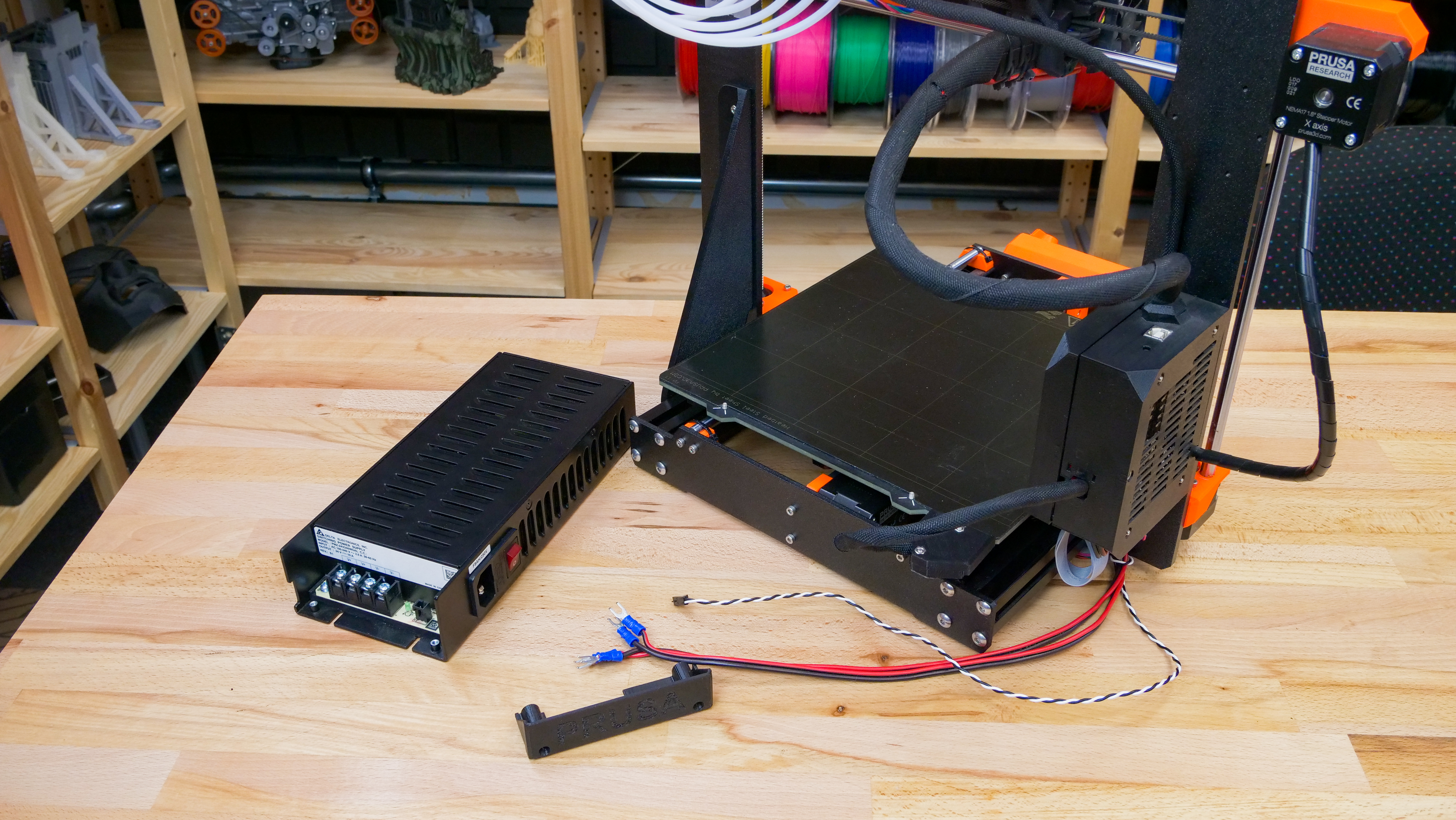
Silver PSU
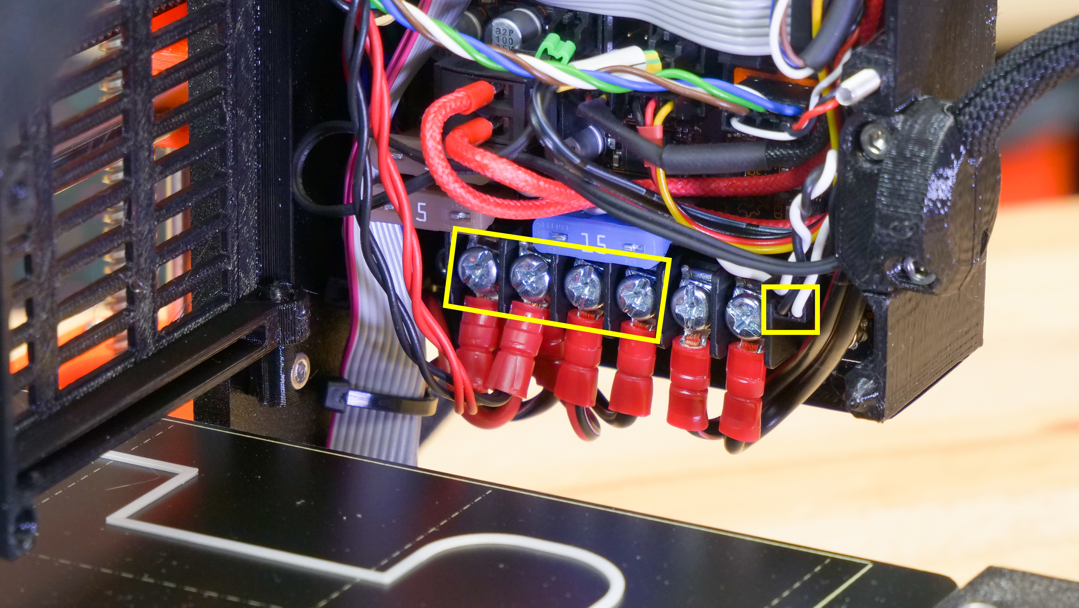
- Open the Einsy electronics cover and disconnect the power cables and power-panic cable from the Einsy board terminal (2x black cables with the fork, 2 red cables with the fork, 1 black and white twisted pair).
- Carefully cut off the zip ties that hold the cables, unscrew the PSU, and remove it along with the cables from the frame.
- Mount the frame brace in place of the PSU.
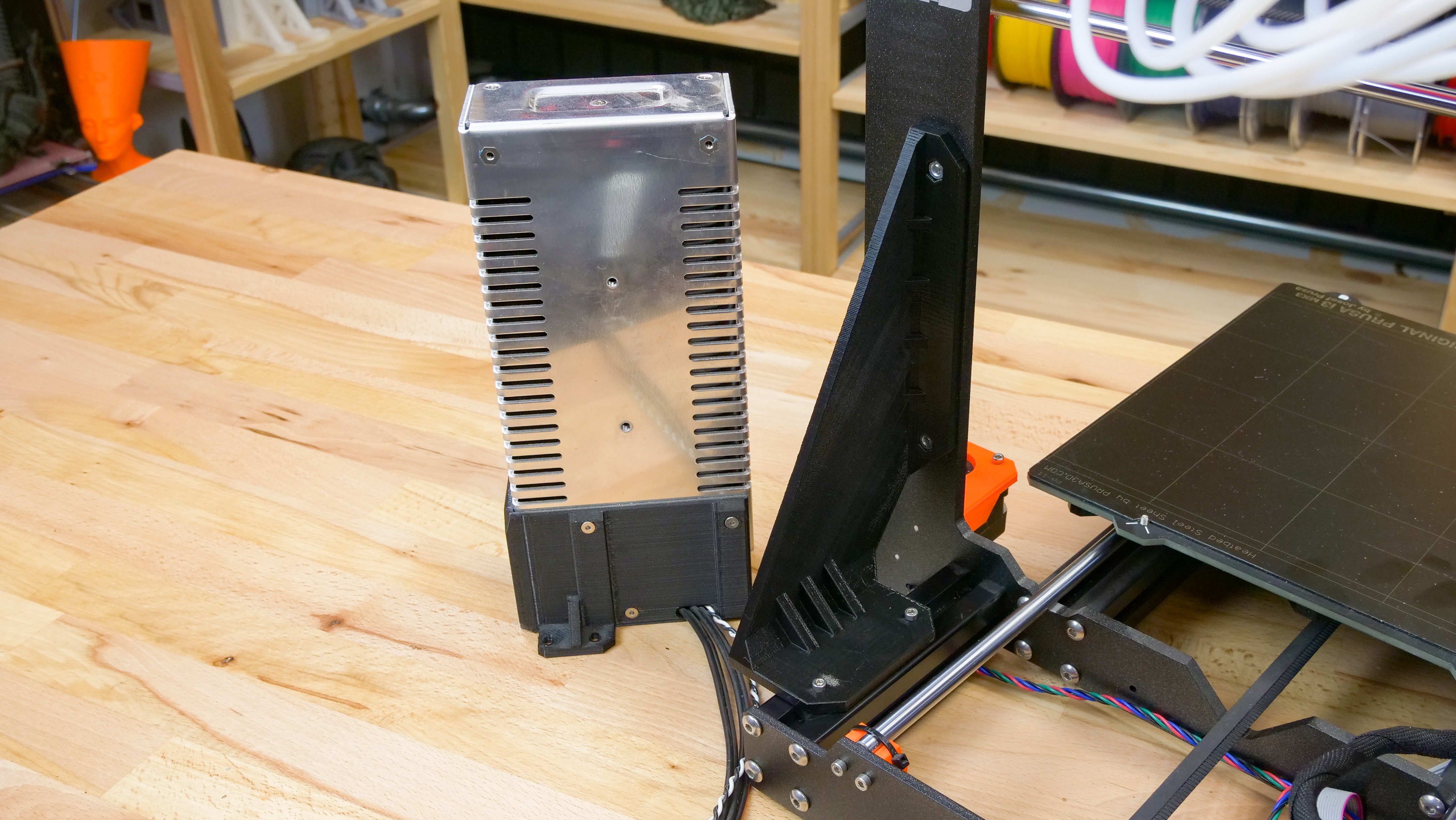
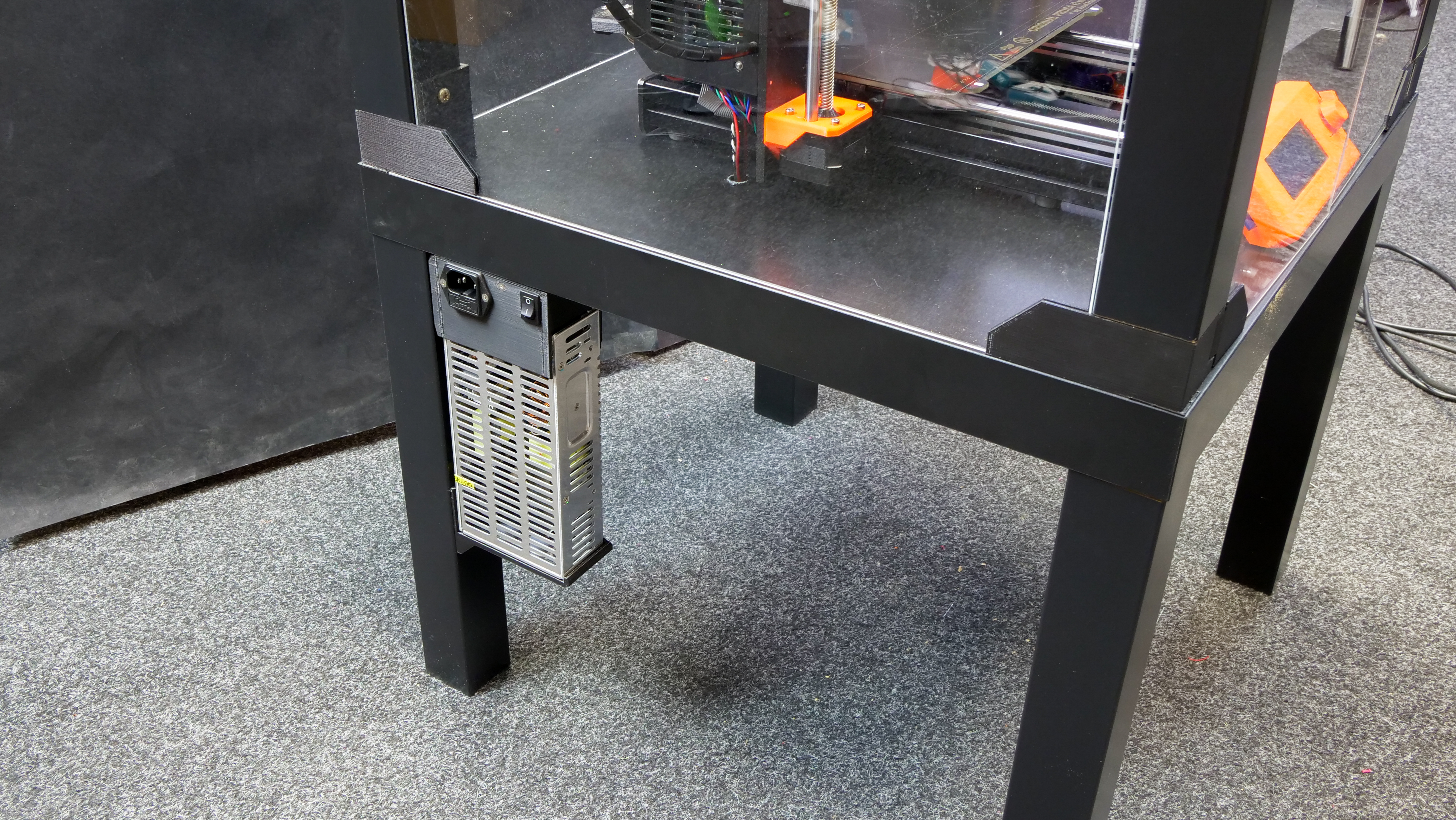
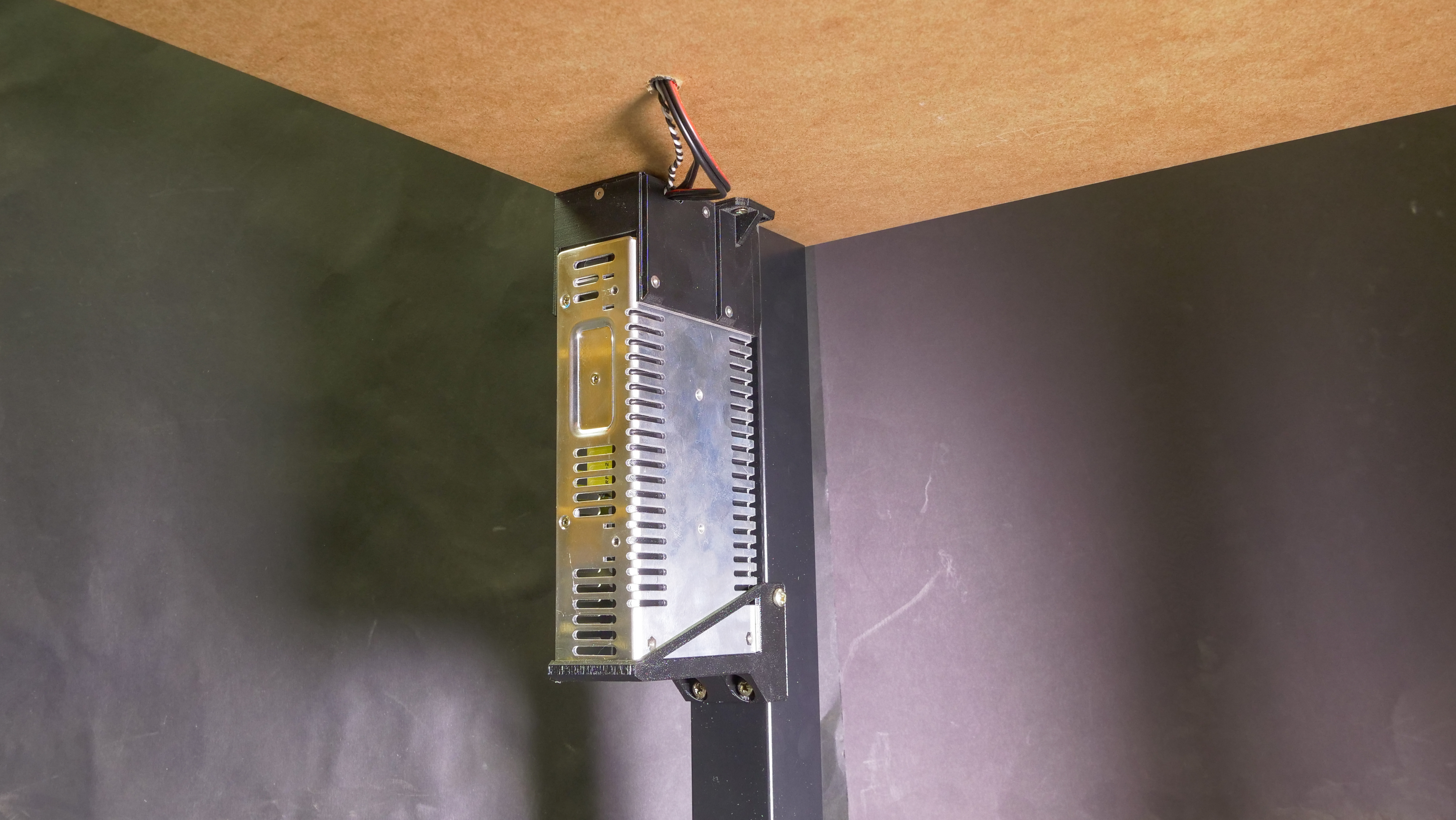
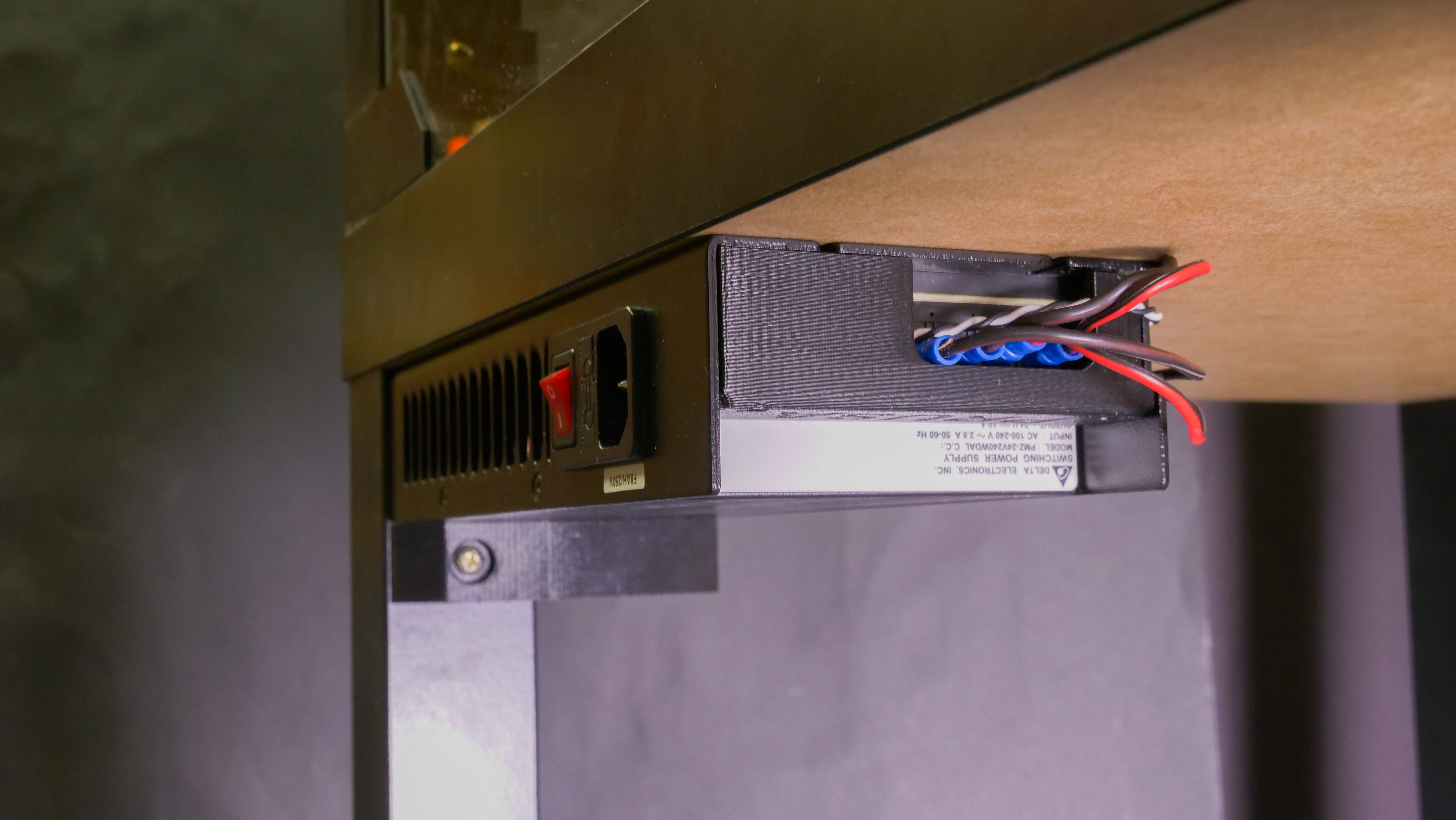
- Mount the printed PSU holder on the left rear leg of the lower table. See the photo below.
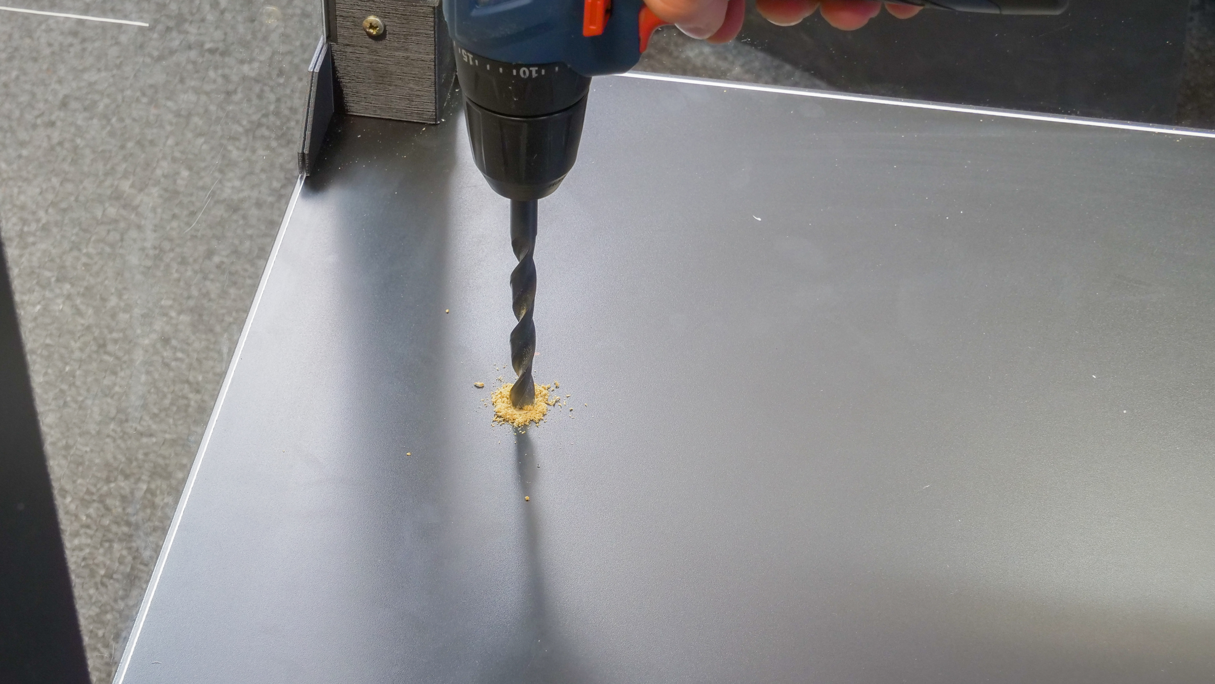
- Drill a 12 mm diameter hole in the lower table. The hole should be placed directly under the Einsy electronics (120 mm from the left edge and 220 mm from the back edge). Insert the cable tube into the hole.
- Slide the PSU into the holder and secure the PSU with a screw to prevent it from moving.
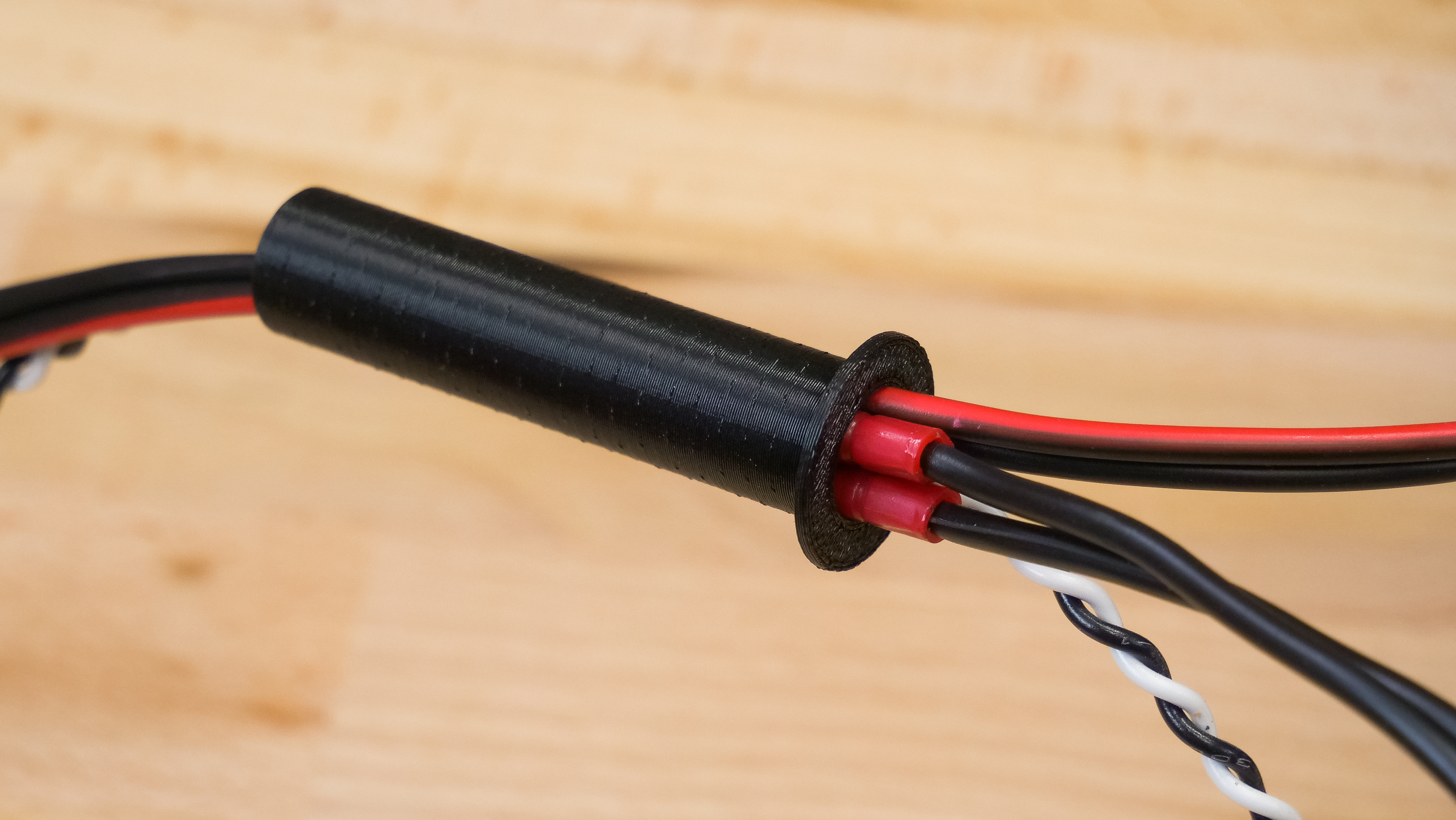
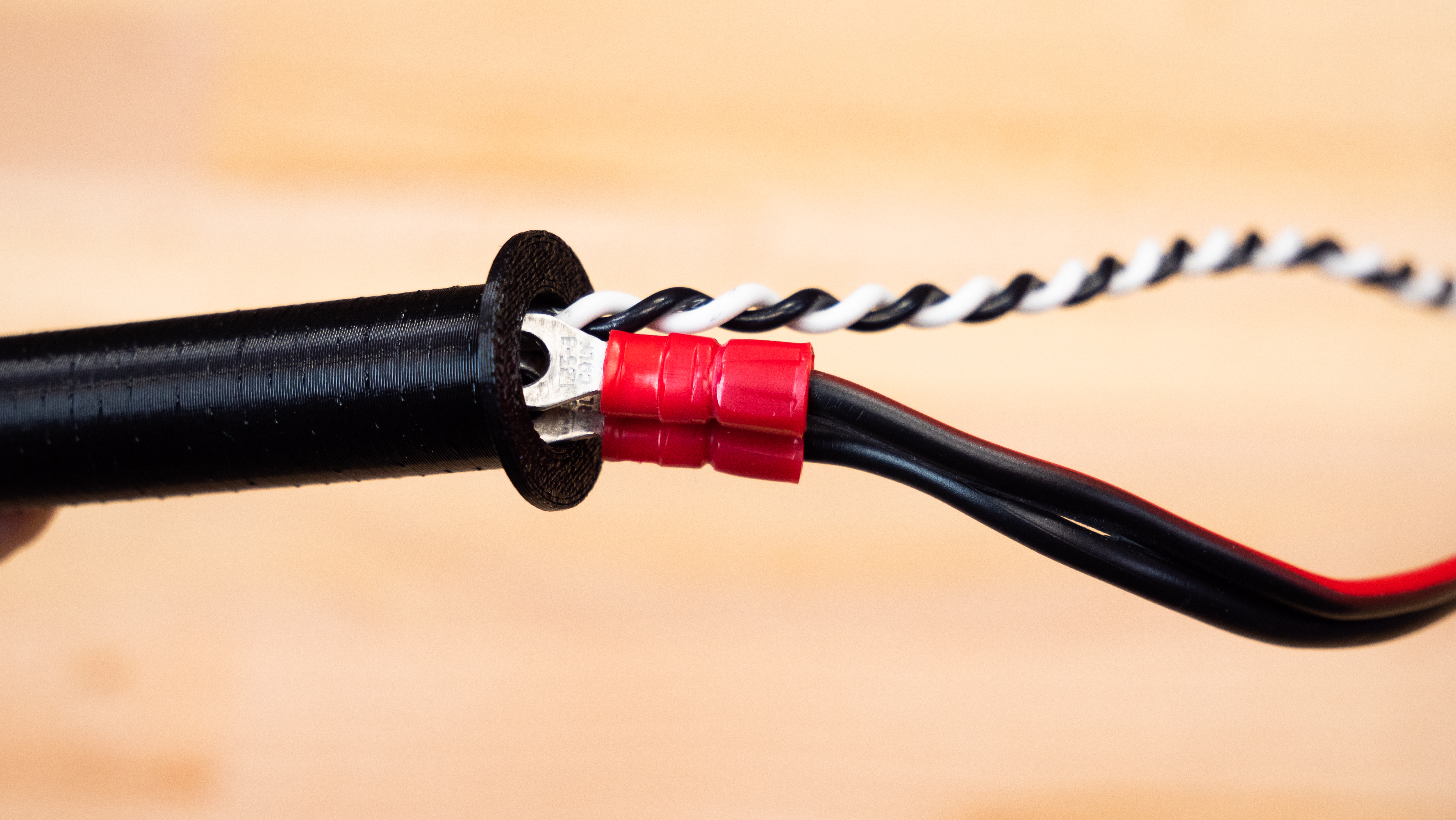
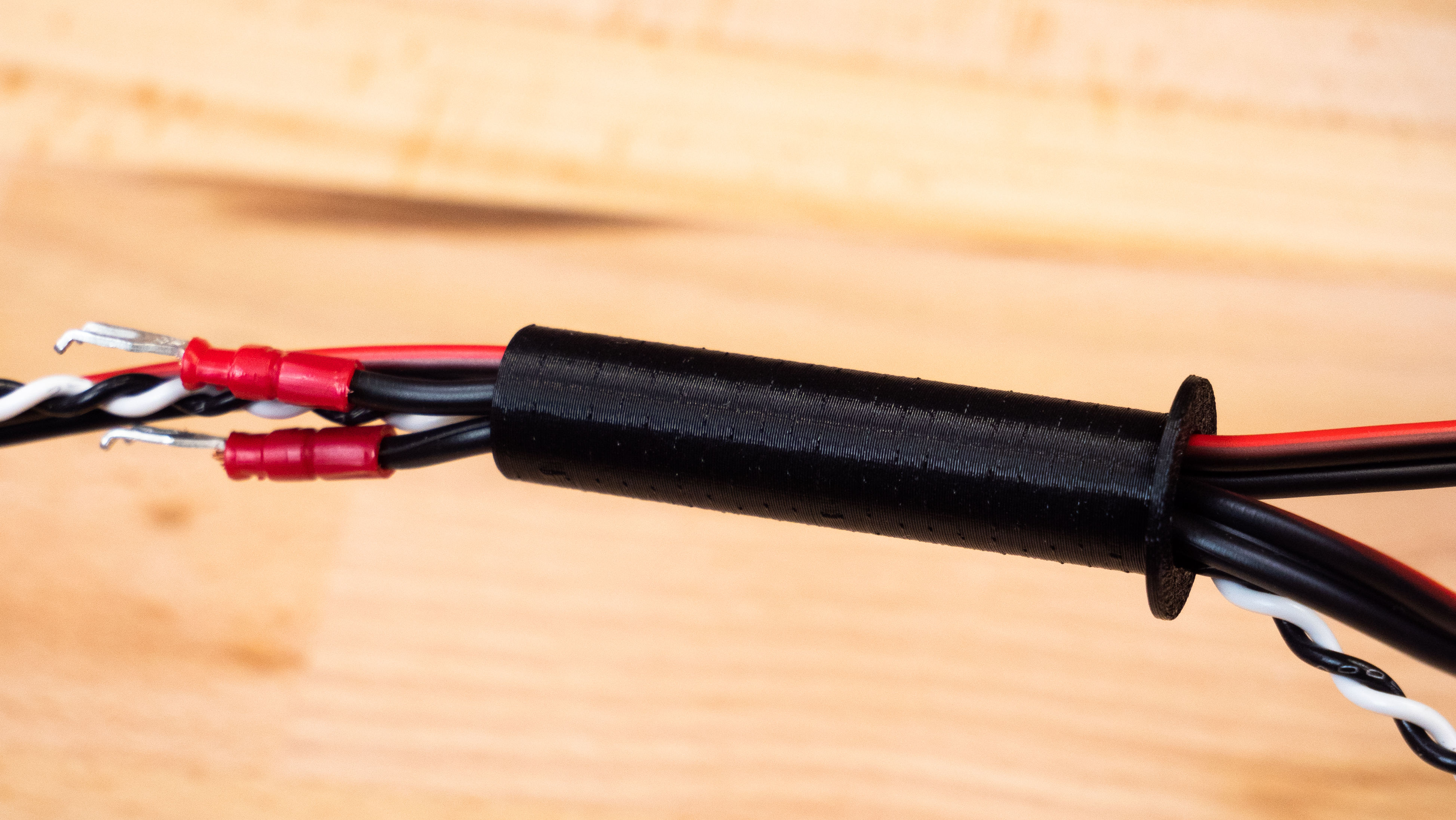
- Pass the cables through the cable tube. The cables must be pulled gradually and the correct order must be followed. First, pull the twisted black-and-white cable. Then continue with the first pair of black and red cables. Finally, pull the second pair of black and red cables. It can be slightly difficult to pull the cables through – try adjusting them and find the optimal position of the terminals to create a passage. If you cannot pull the cables through, separate the beginning of the black cable from the red one and push them separately.
- Connect the cables back to the Einsy electronics. Remember the correct polarity of the cables. If you’re not sure, check out the assembly manual.
Black PSU
- Remove the plastic cover on the power supply labeled “PRUSA”. Disconnect all cables connected to the power supply.
- Unscrew the power supply and remove it from the frame.
- Remove the zip ties that hold the cables on the frame and remove the PSU cables from the bundle. However, do not disconnect the cables from the Einsy board!
- Secure the remaining cables with a zip tie.
- Mount the frame brace in place of the PSU.
- Mount the printed PSU holder on the left rear leg of the lower table.
Check out the photo below. - Drill a 12 mm diameter hole in the lower table. The hole should be placed directly under the Einsy electronics (120 mm from the left sedge and 220 mm from the back edge). Insert the cable tube into the hole.
- Pass the cables through the cable tube. The cables must be pulled gradually and the correct order must be followed. First, pull the twisted black-and-white cable. Then continue with the first pair of black and red cables. Finally, pull the second pair of black and red cables. It can be slightly difficult to pull the cables through – try adjusting them and find the optimal position of the terminals to create a passage. If you cannot push the cables through, separate the beginning of the black cable from the red one and pass it separately.
- Connect all cables to the power supply. Remember the correct polarity of the cables. If you’re not sure, check out the assembly manual.
- Place the power supply into the bracket and secure it on the terminal board side with one screw to the table.
- Remount the power supply cover labeled “PRUSA”.

Building the box – upper cover
List of plastic parts for the upper plate:

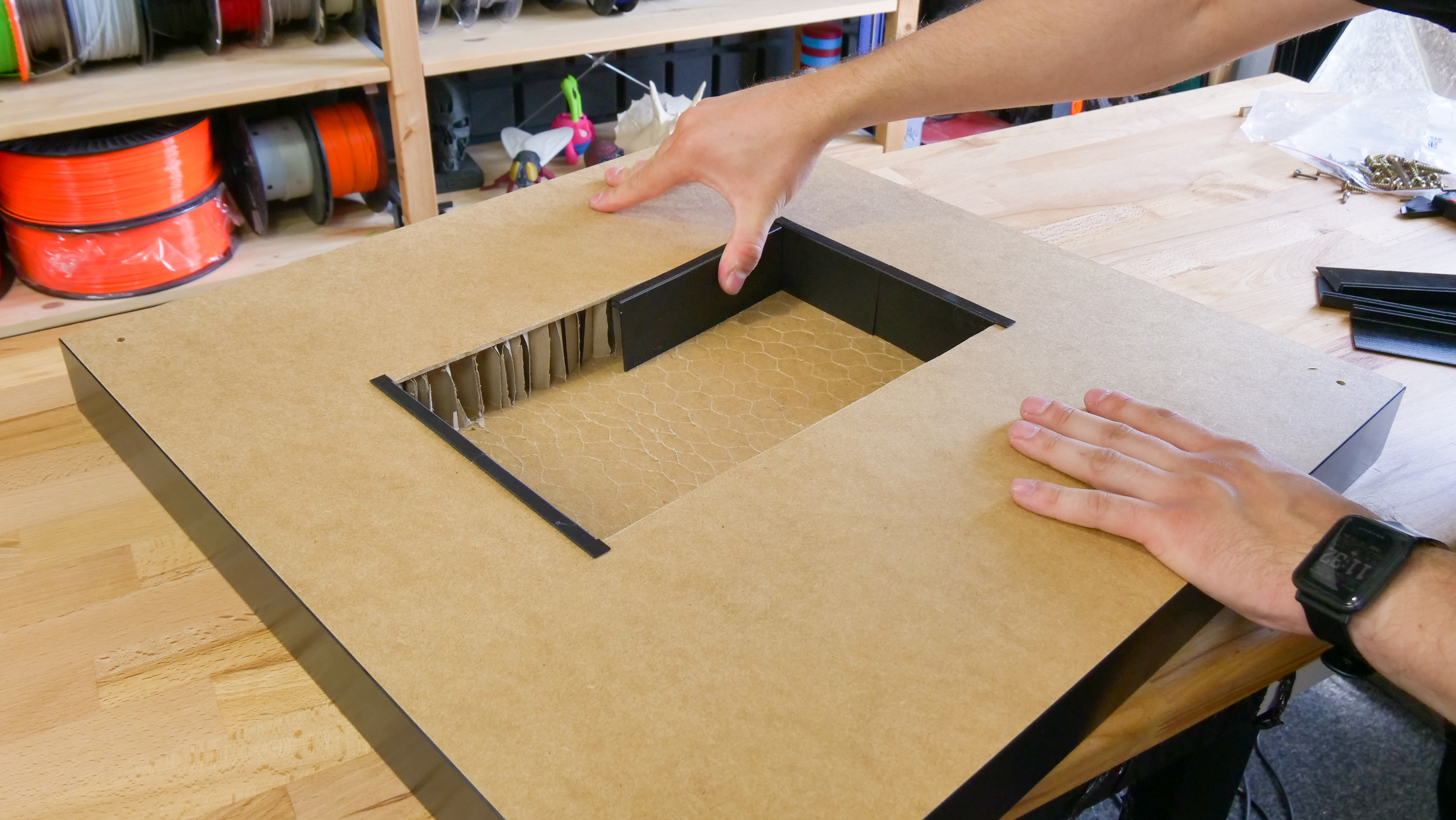
Hollowing the upper cover
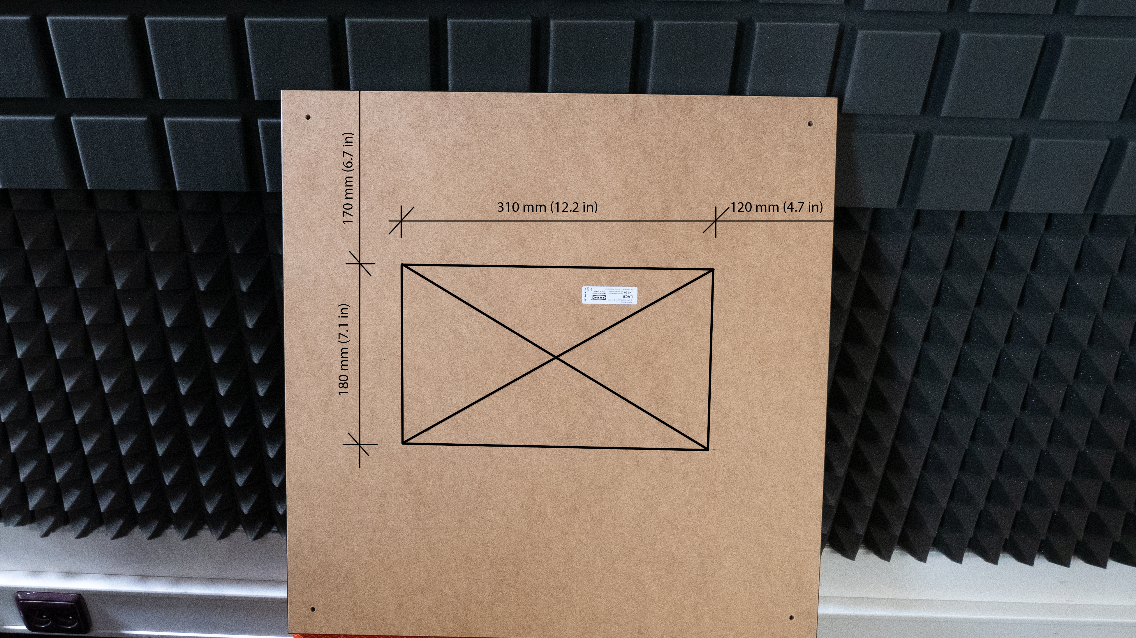
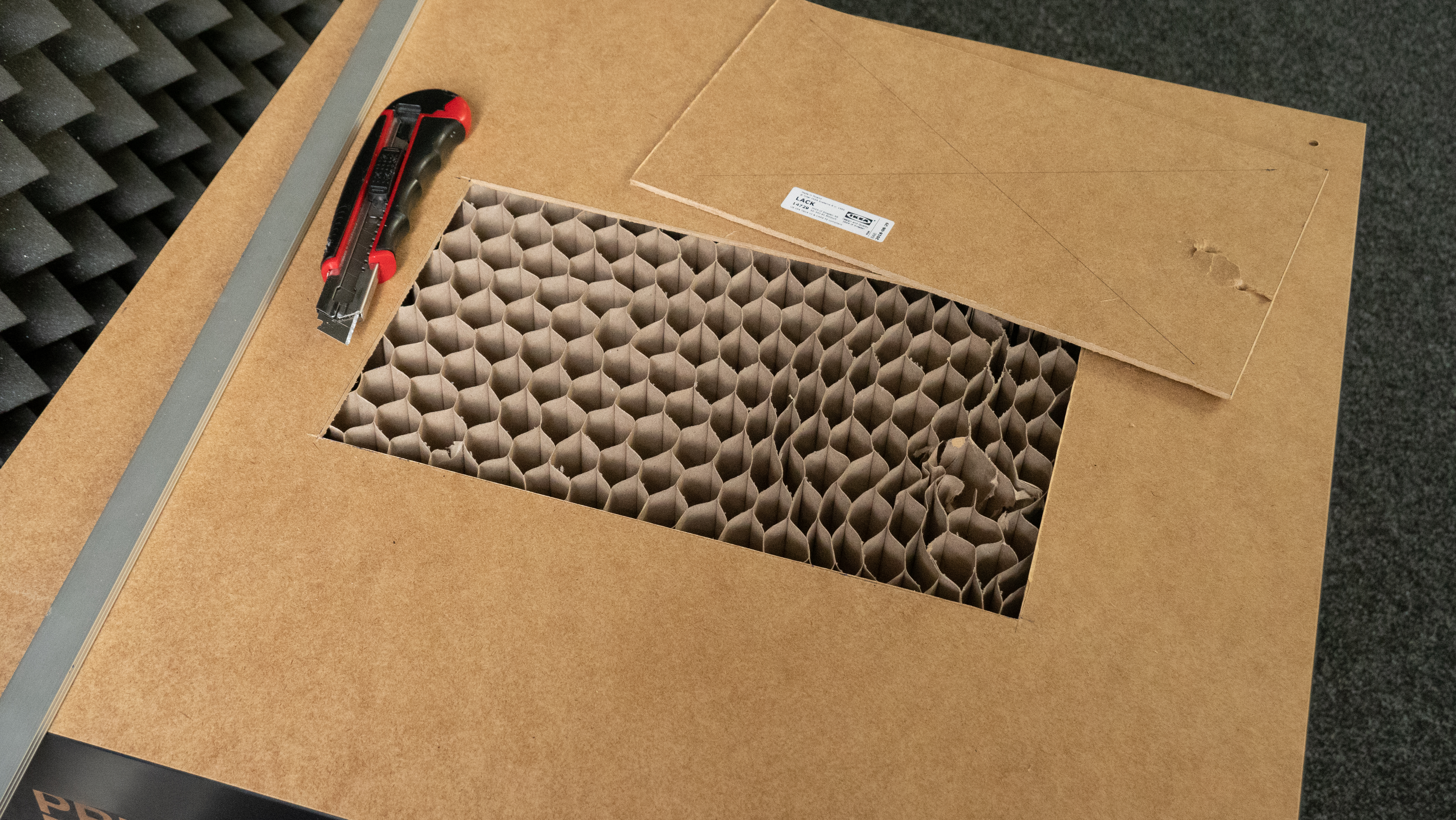
To accomodate the orange PTFE tube leading from the MMU2 unit to the extruder, we need to cut away some material from the table top. Turn it upside down, so you have access to the underside (light brown color). Use a ruler and a pen to draw a rectangular shape with the dimensions and placement based on the photo above. Take a snap-off knife and a ruler and start by cutting a rectangular opening. Then, use the knife to remove the paper honeycomb pattern inside the table top – leave the top plate untouched, there’s no need to make a hole through the whole panel (see the third photo above). Take the printed parts and put them around the opening to prevent the paper infill from falling onto the printer.
Supporting arm for the top cover
List of plastic parts for this step:
Hinges, supporting arms and centering cap
List of plastic parts for this step:
1× Prusa_MMU_enclosure_centering_part
1× Prusa_MMU_enclosure_top_desk_hinge_right
1× Prusa_MMU_enclosure_top_desk_hinge_left
all included in Prusa_MMU_enclosure_4.3mf

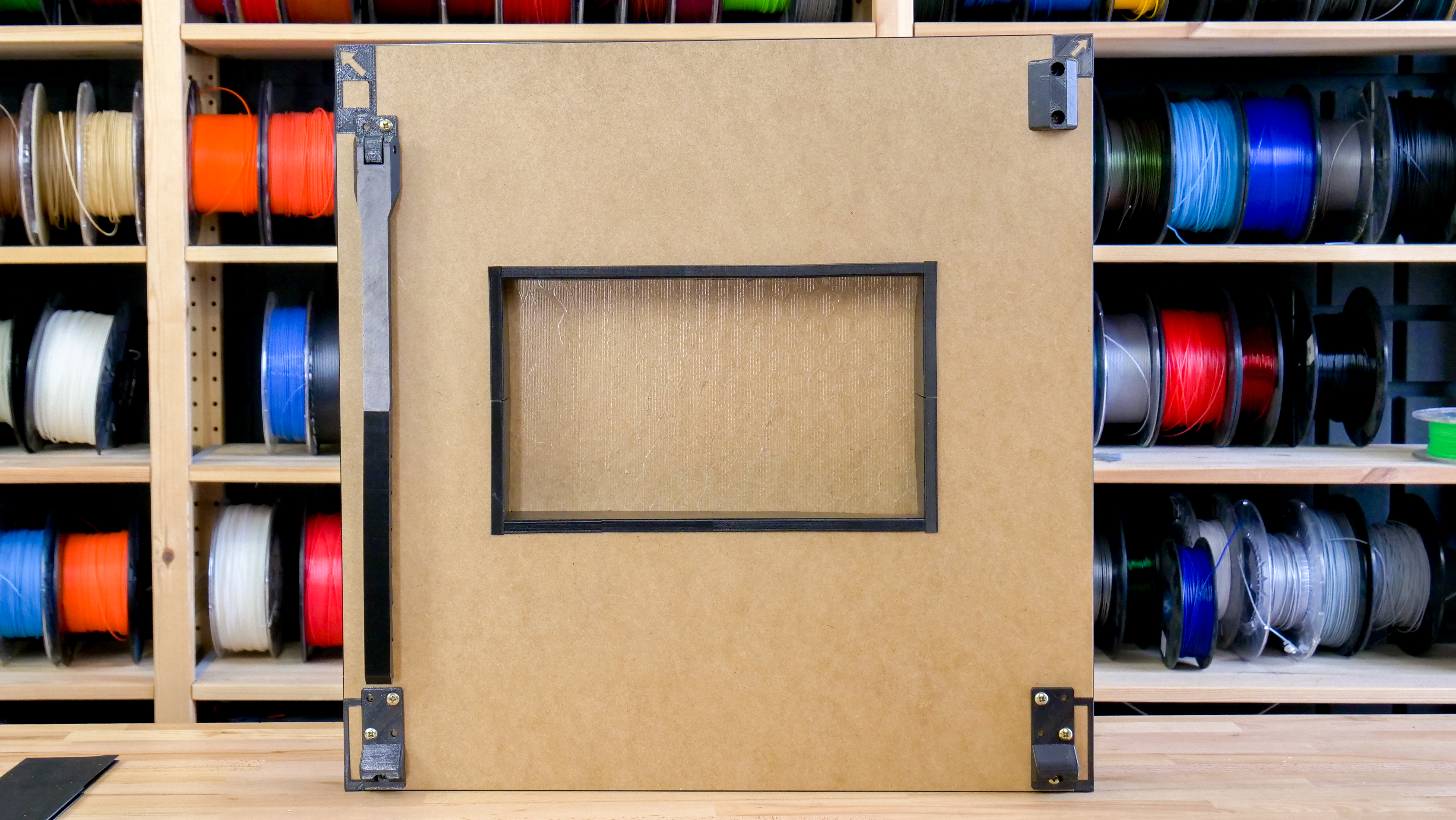
Throughout this step, make sure that the table top is facing the right way. The cutout is not directly in the middle! The top edge of the cutout is the one that’s 170 mm from the edge of the table.
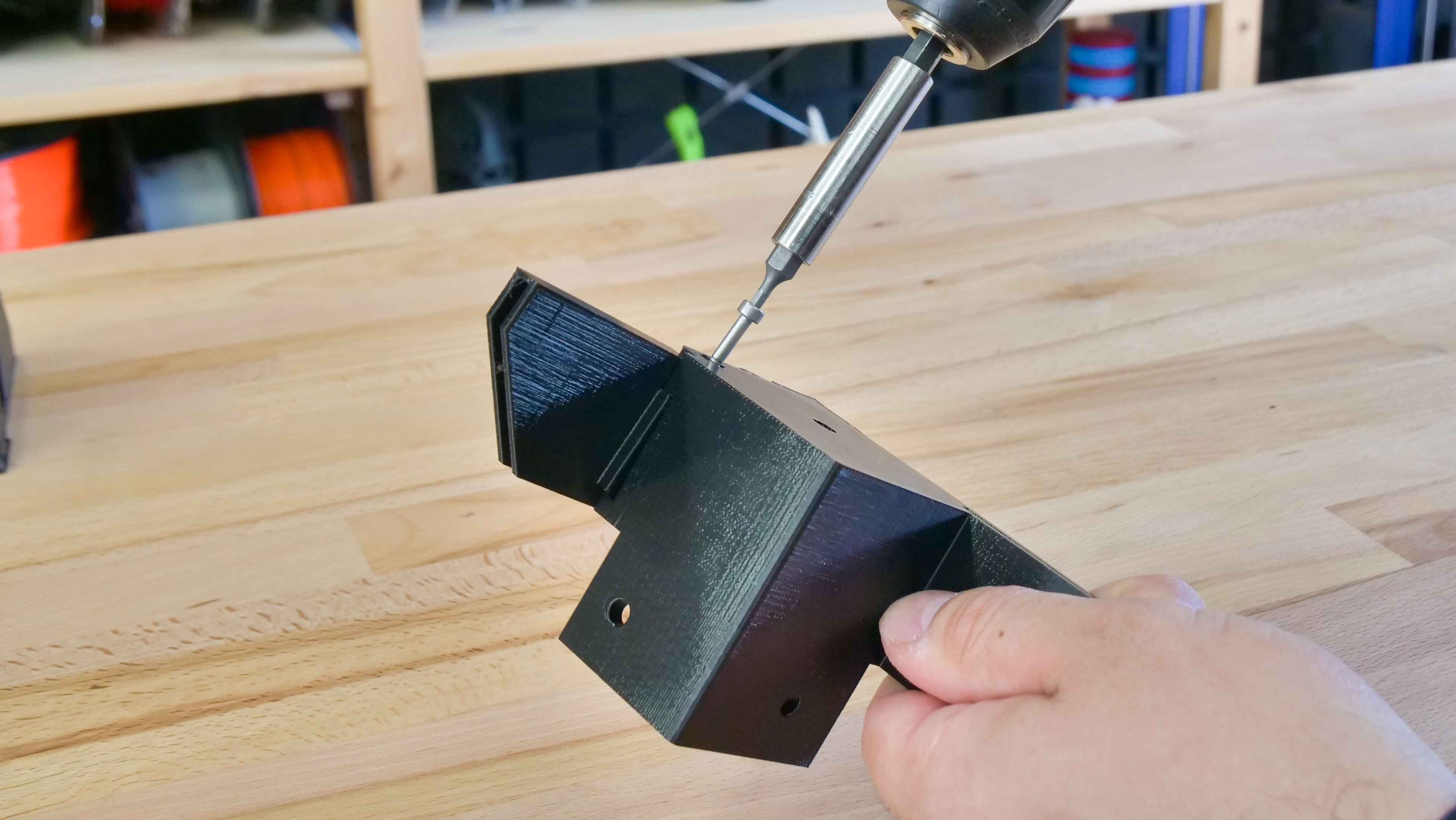
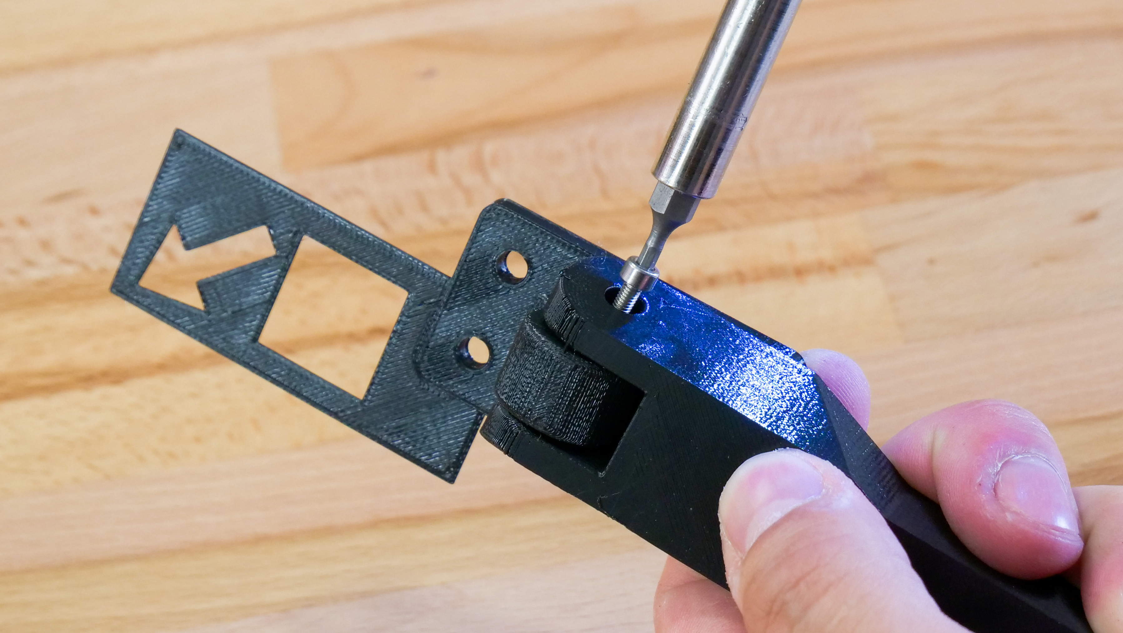
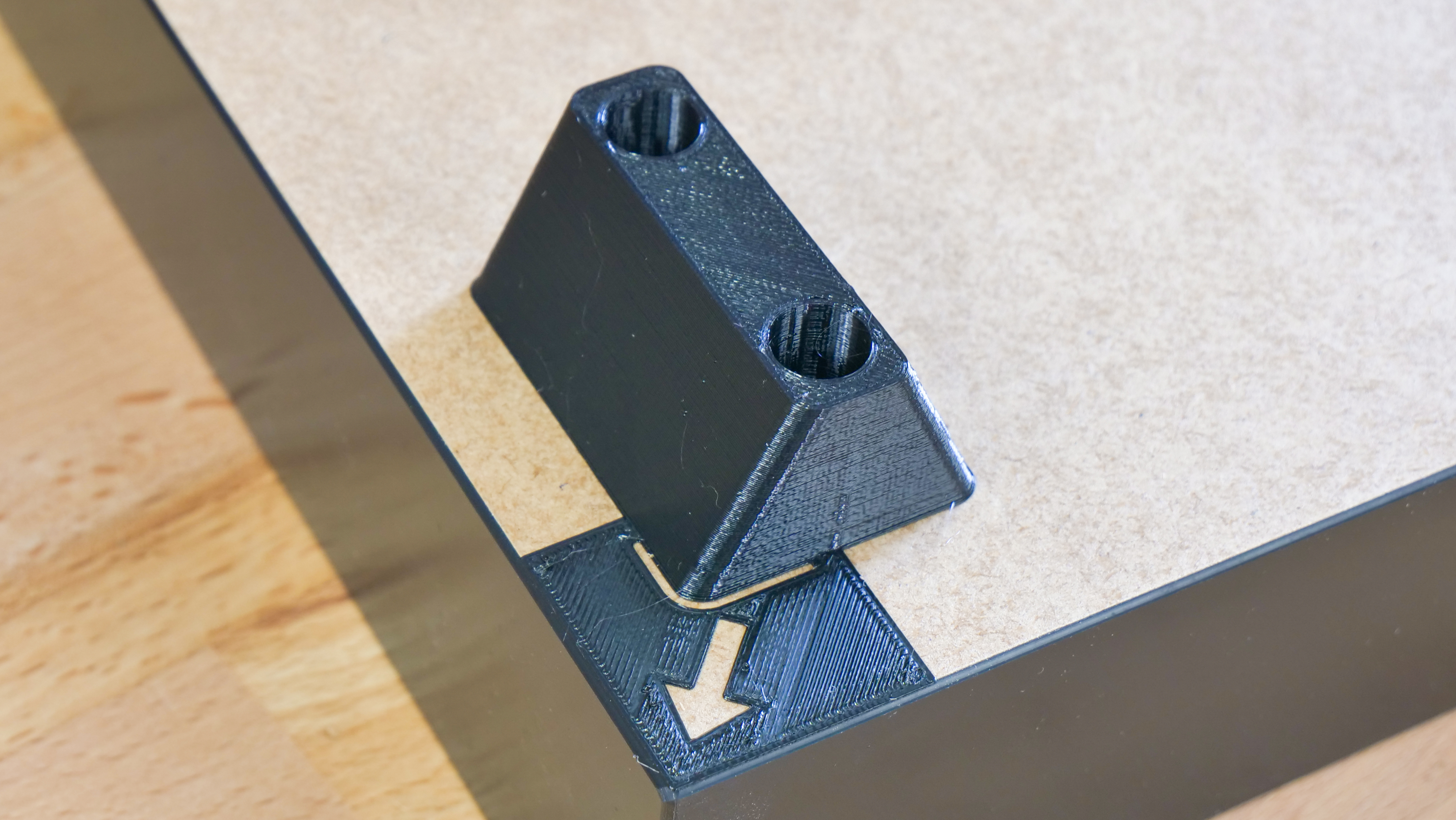
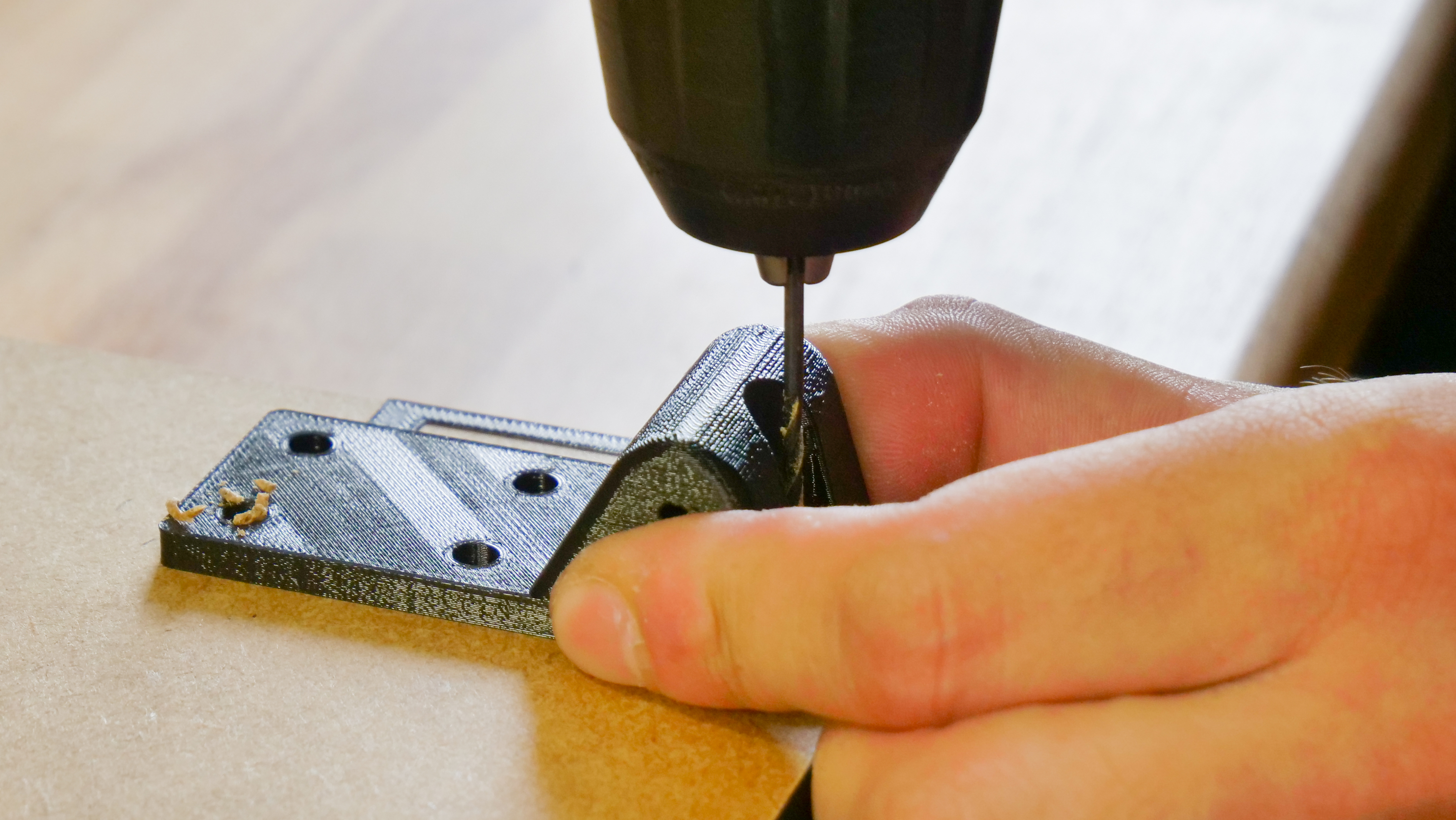
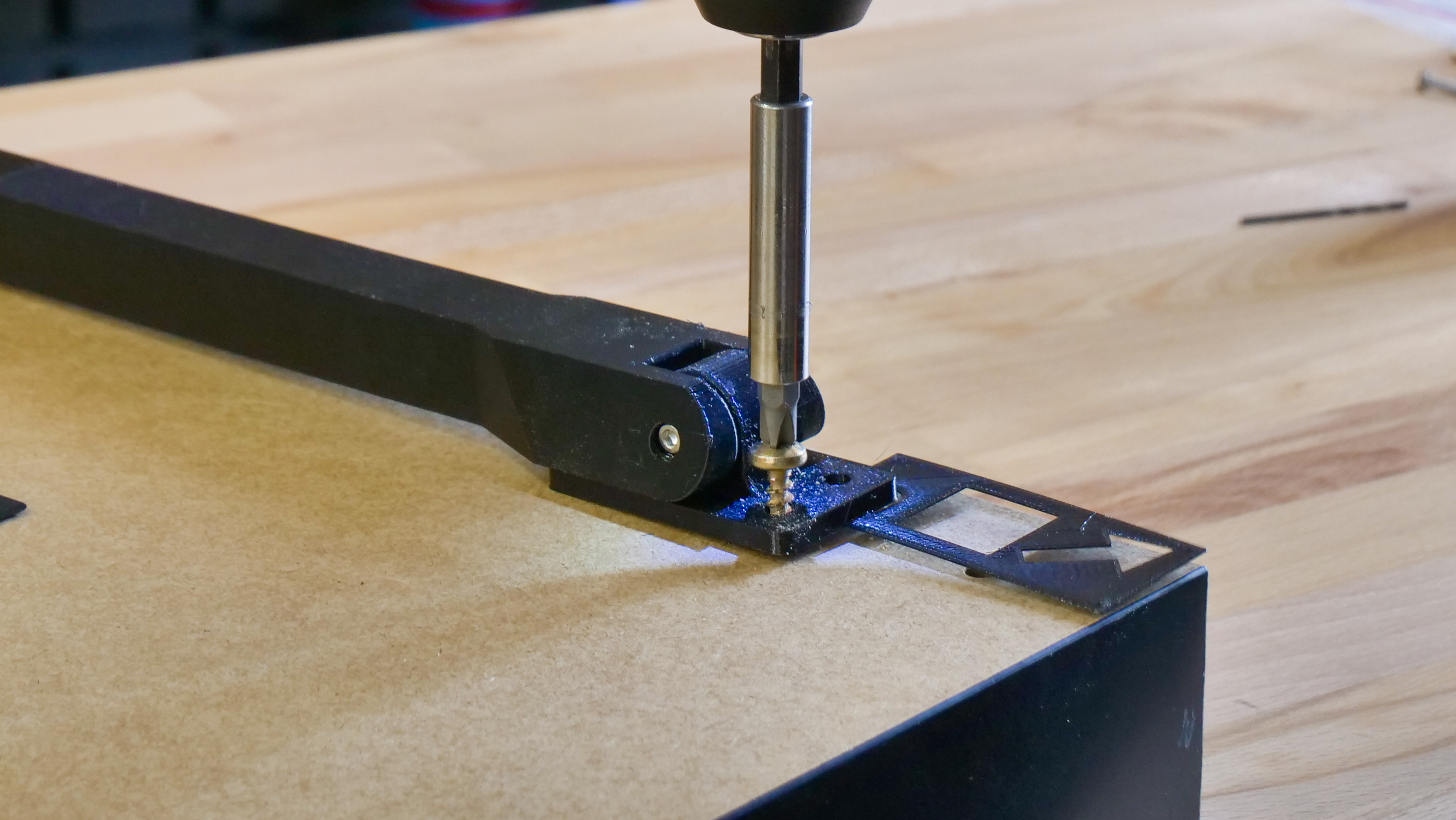
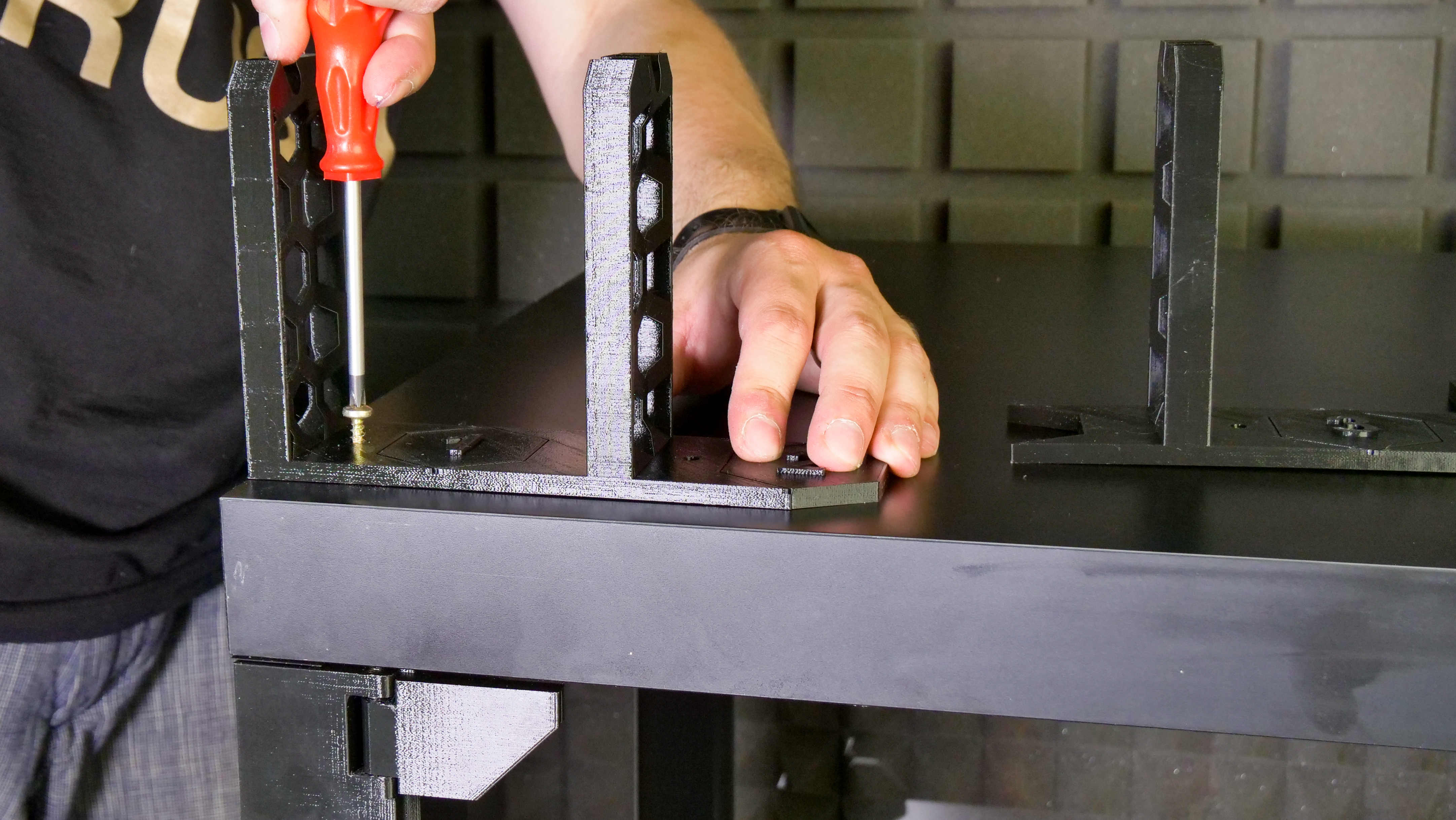
Every part that needs to be secured to the table top comes with a mounting bracket that will help you align it and secure it in place. Before you secure the parts with screws, we recommend to drill the holes first – use a 2mm drill bit. Then, secure the parts with 5×20mm screws.
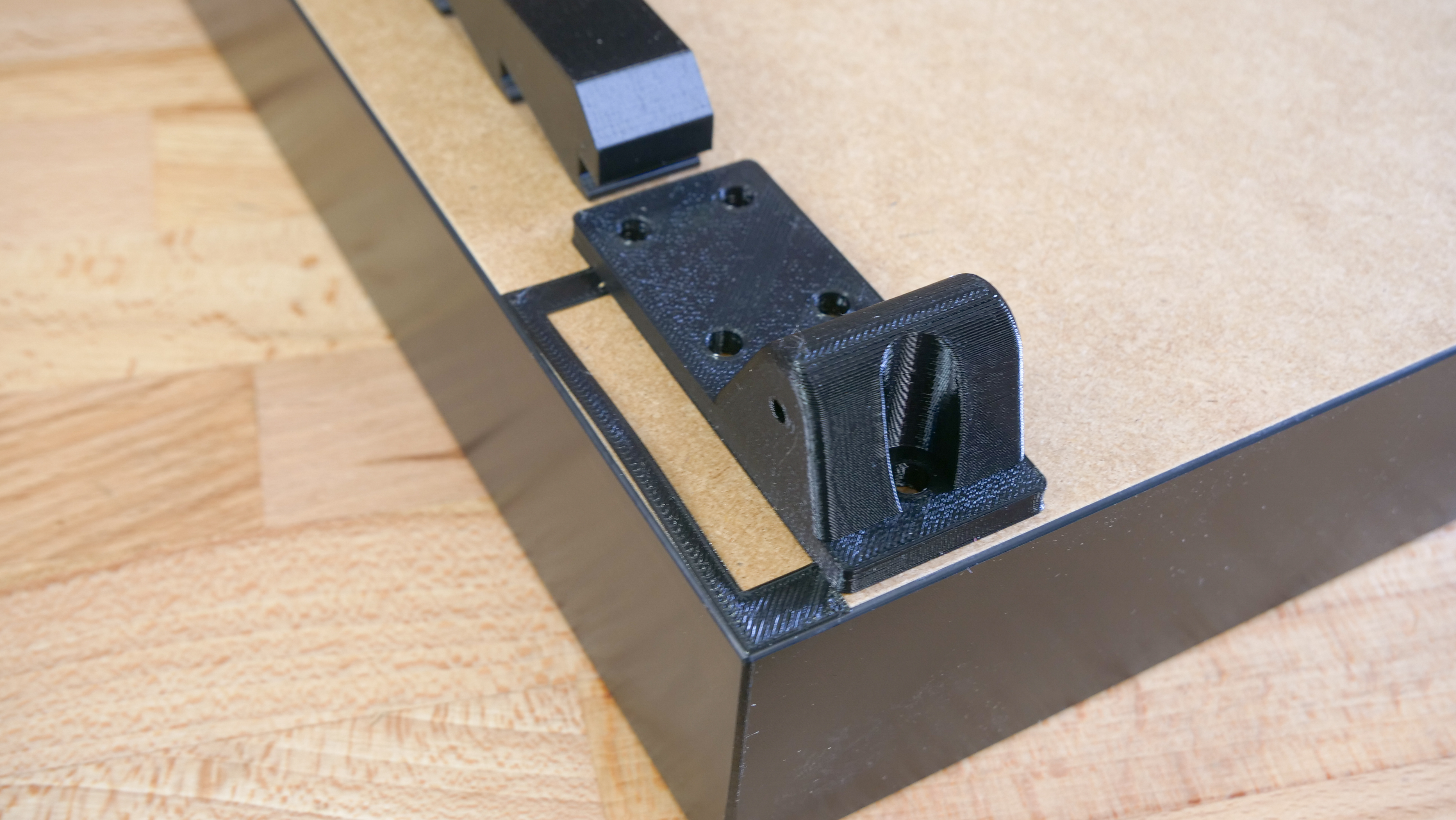
The front left corner is where the supporting arm goes. Front right corner is the place for the centering cap. Hinges go to the back.
Preparation of the rear acrylic sheet window

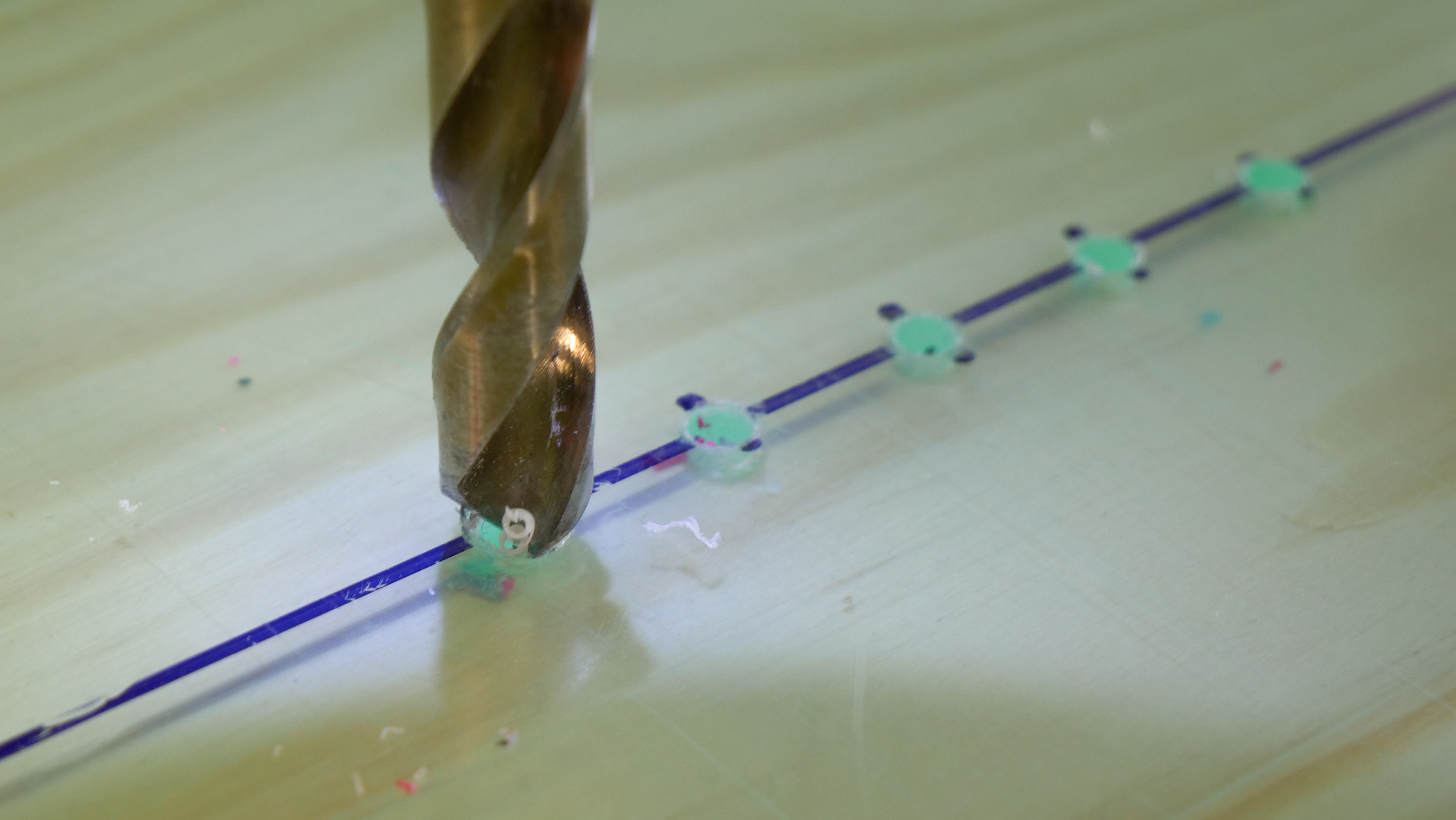
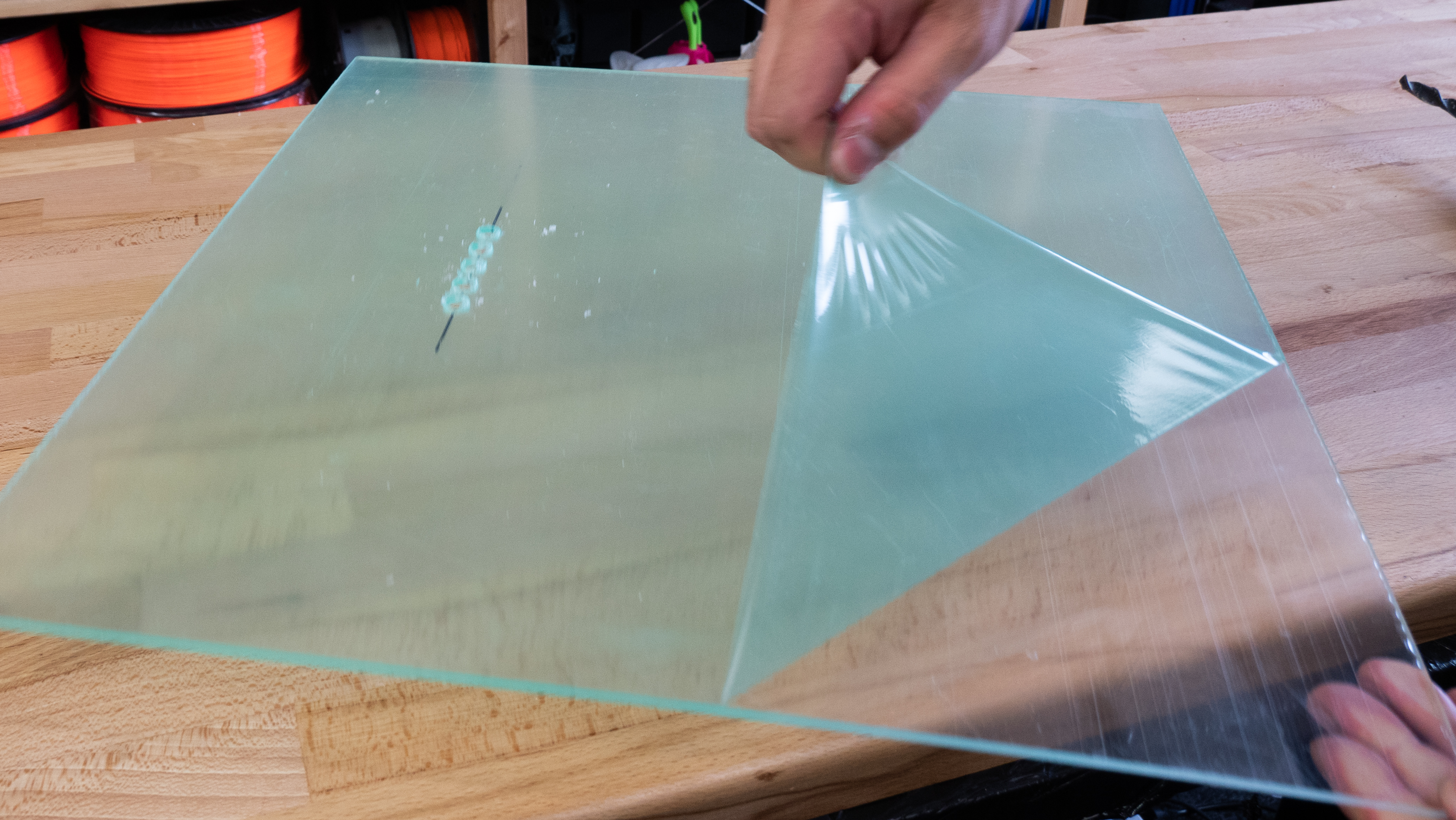
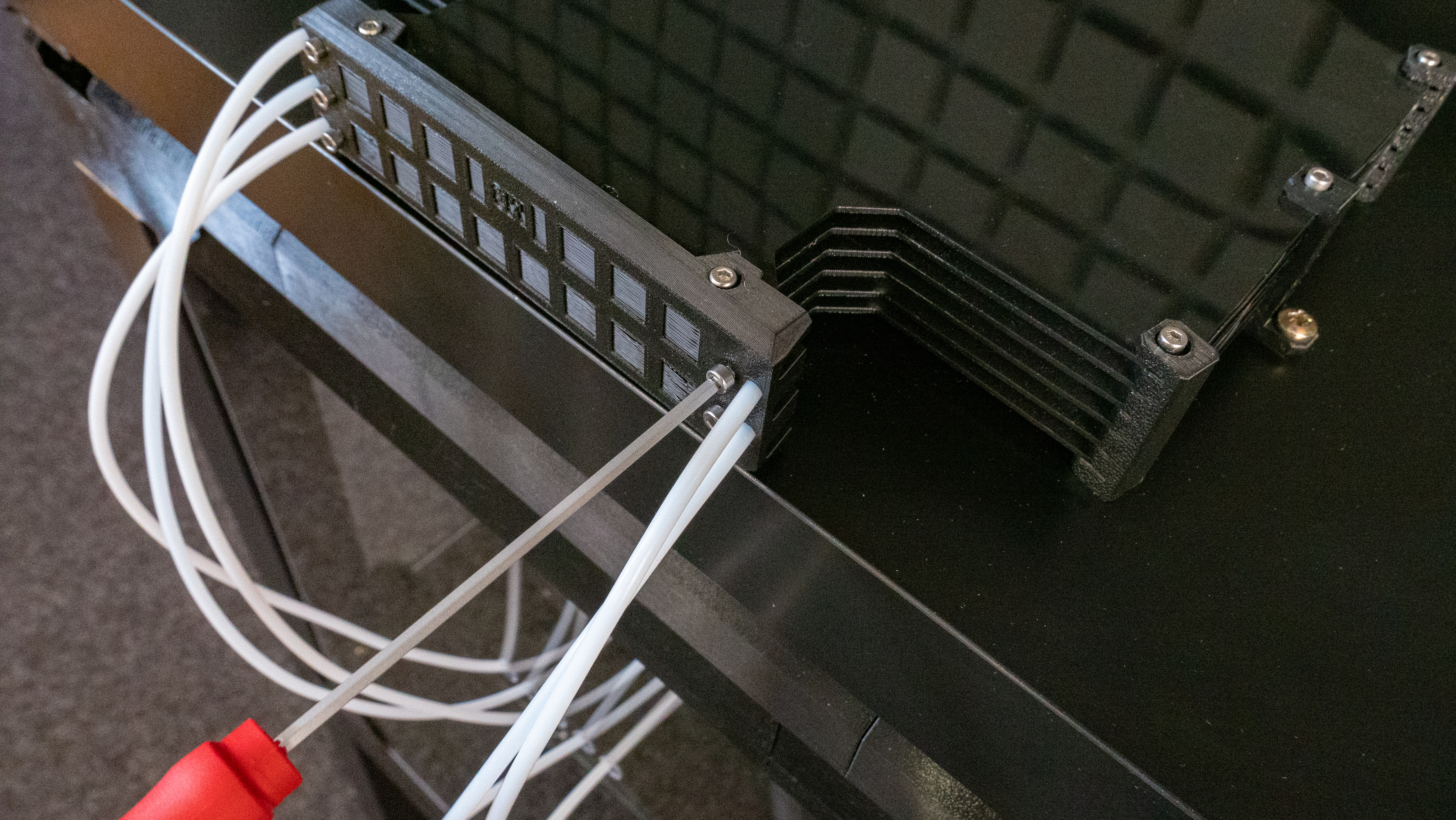
Next, we need five circular openings in the rear acrylic sheet window – these are for the PTFE tubes. If you don’t have the holes there yet, you need to drill them – this can be done with standard equipment, but do not apply excessive force. The holes should be placed 320 mm from the bottom edge of the sheet and centered horizontally. The distance between centers of the holes is 15 mm. To ensure that the PTFE tubes can move freely through the holes, you should use a 10mm drill – smaller holes could result in trouble with filament movement inside the PTFE tubes.
To drill these holes, start with a ruler and a marker. Mark down the center points for all holes and use a 2mm drill bit first. Then move onto a slightly larger drill bit (e.g. 4-5 mm). Then increase the drill bit size again, until you reach the 10mm drill bit. It’s necessary to move by small increments to prevent the acrylic sheet from breaking. Also, make sure the acrylic panel lays flat on a wooden surface during this process – again, to stop it from breaking.
Assembling the U-frame
List of printed parts for this step:
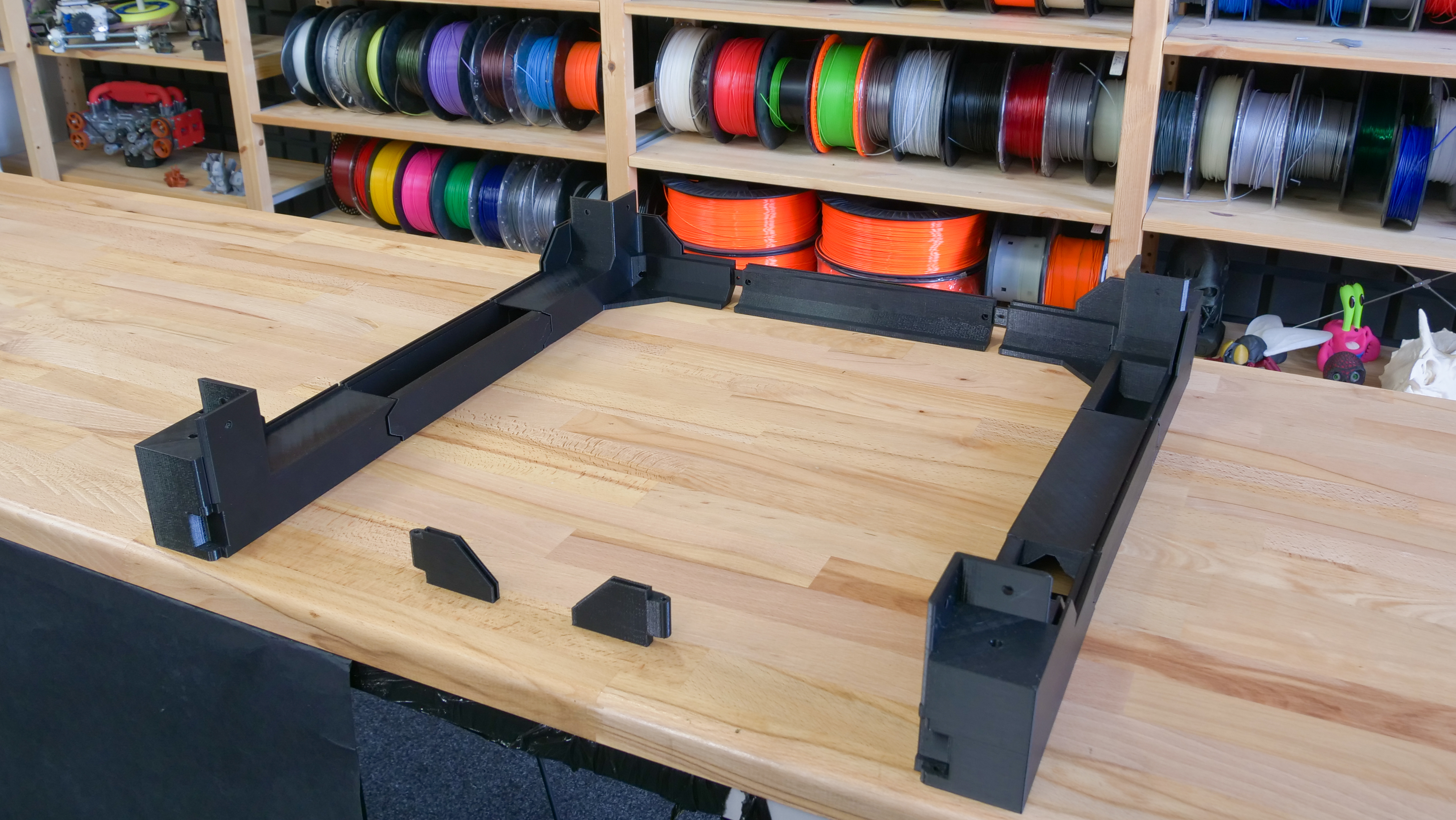
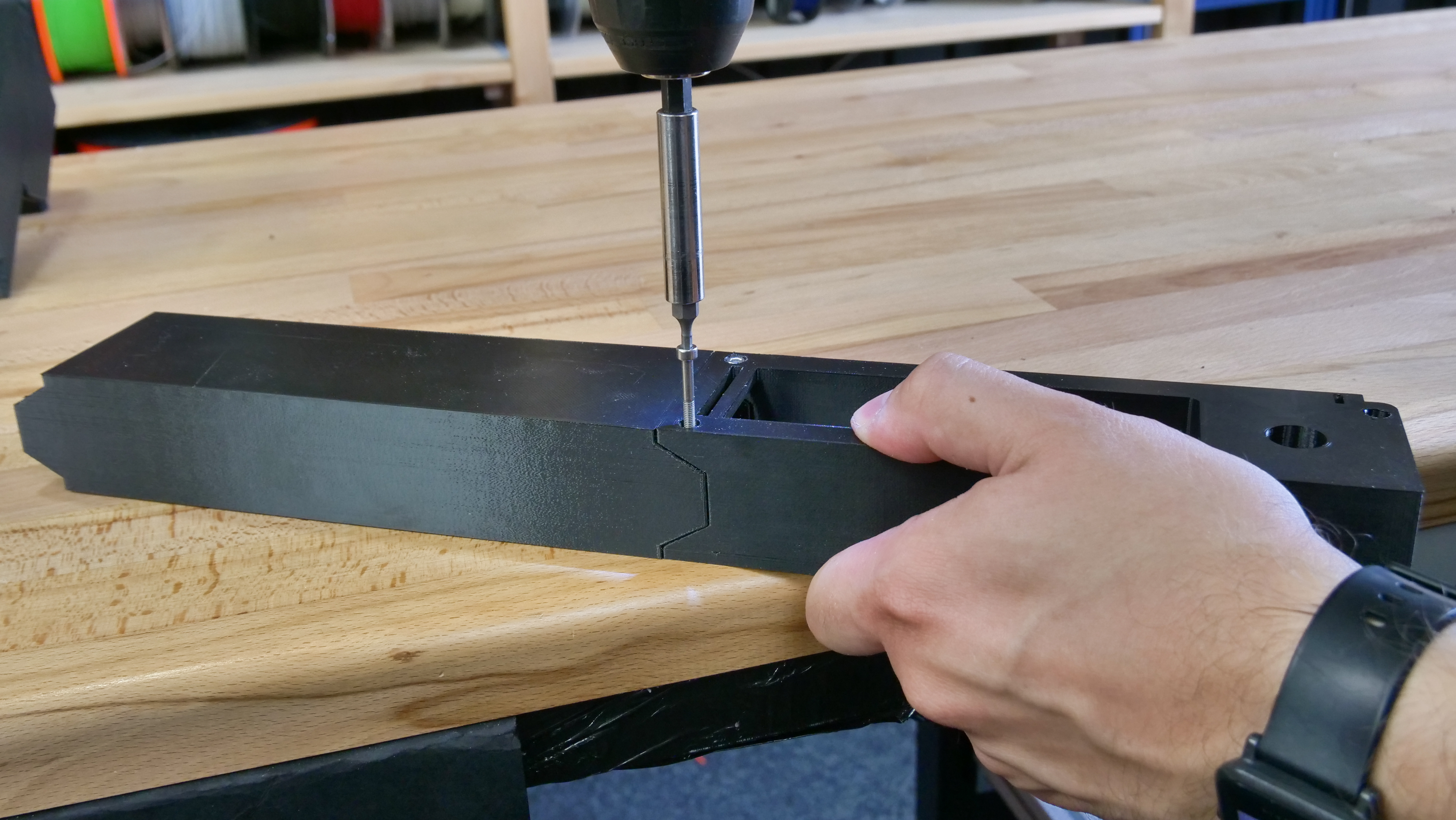
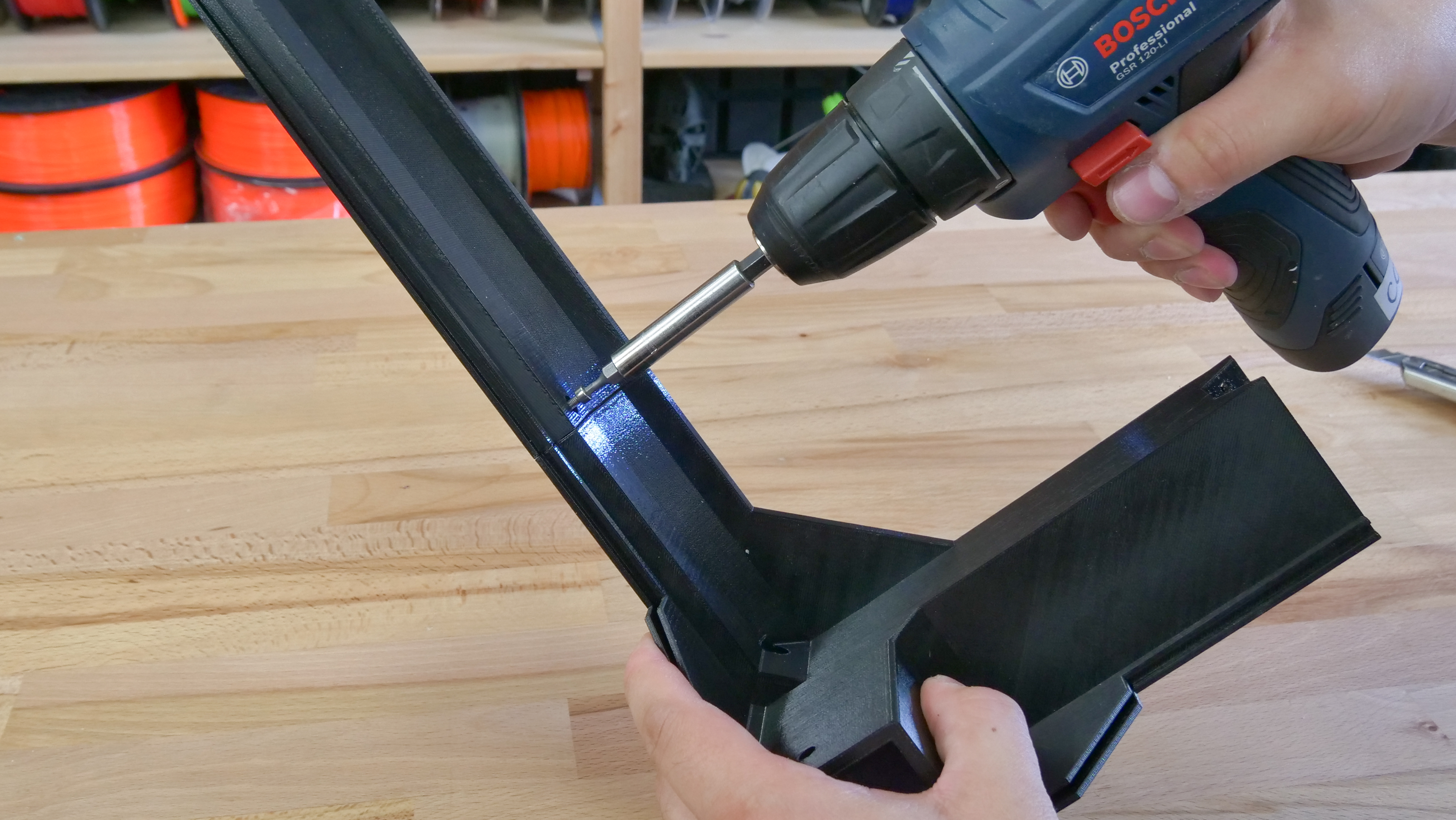
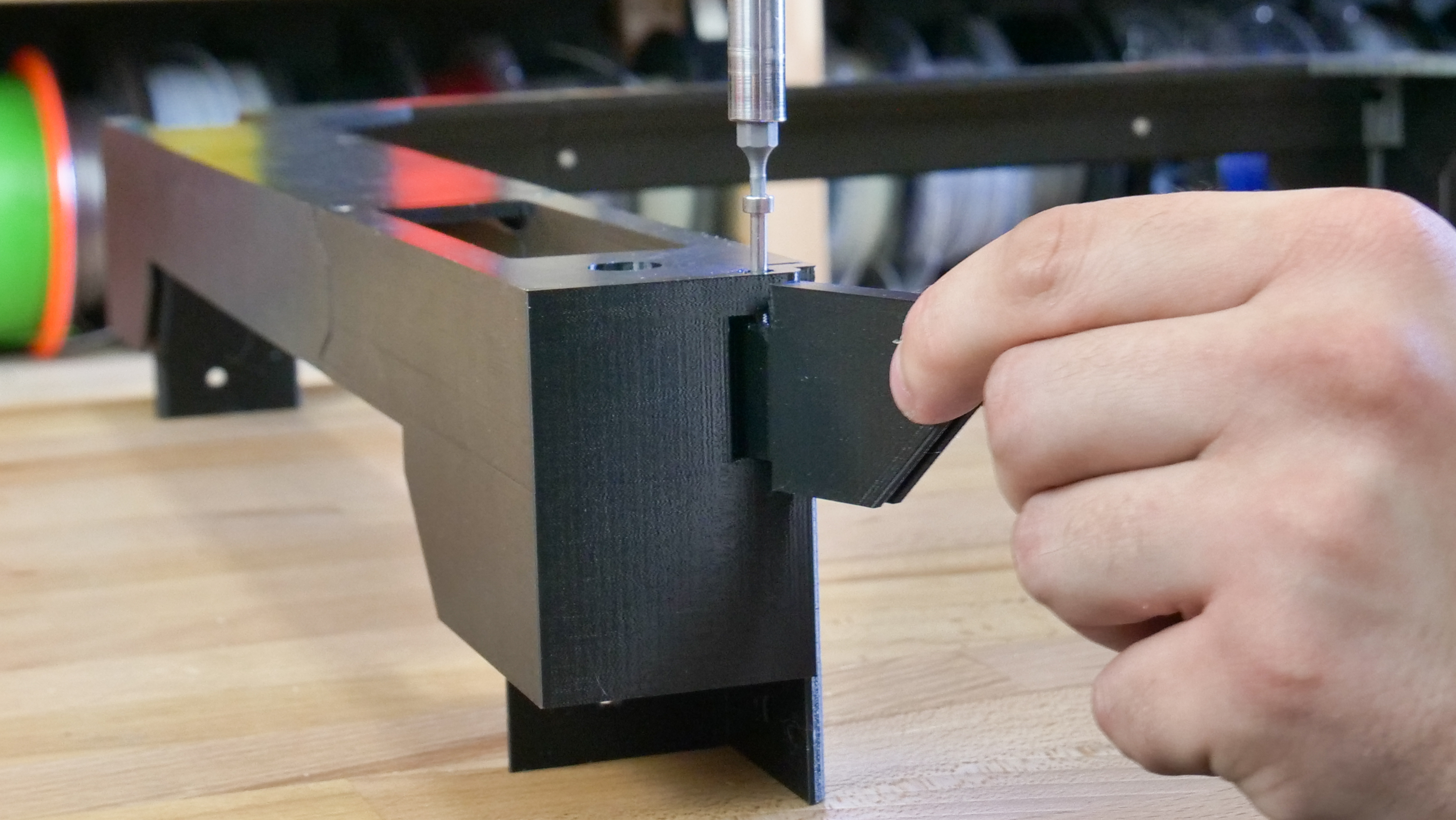
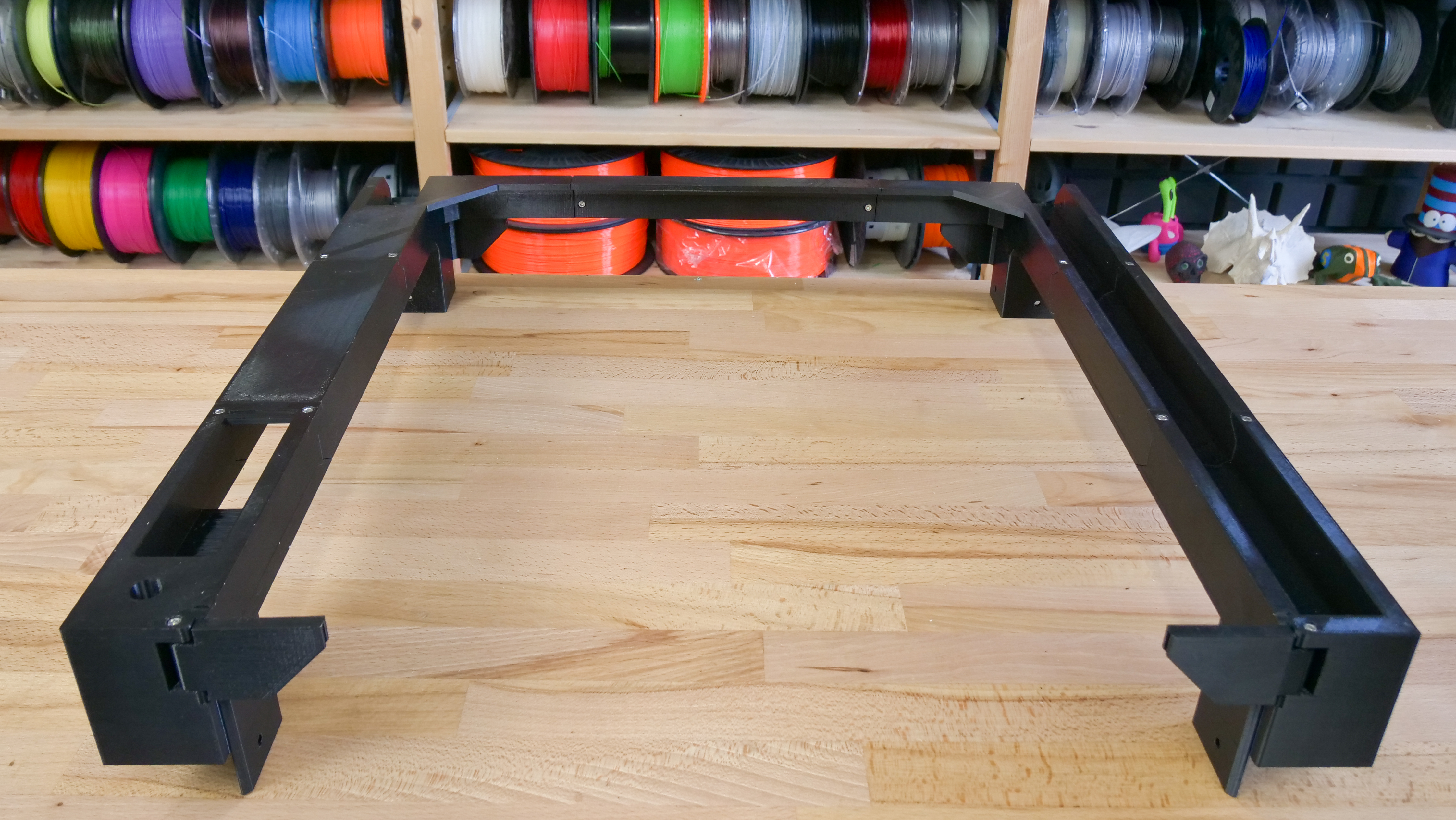
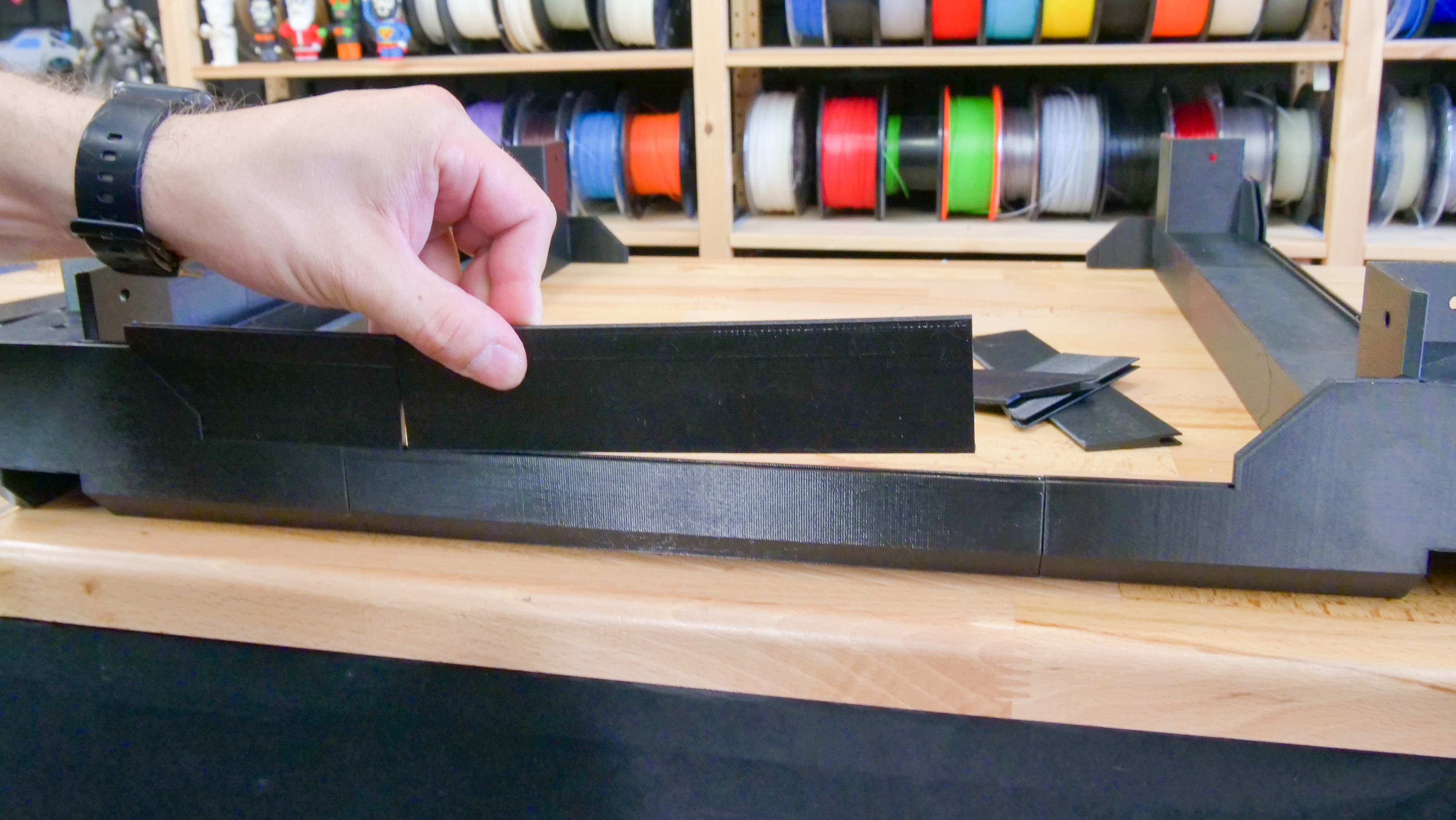
To ensure that the top of the enclosure is strong and firm, the U-frame must be robust. The left side of the U-frame contains a slot for the supporting arm, the right side contains a storage compartment for various small tools.
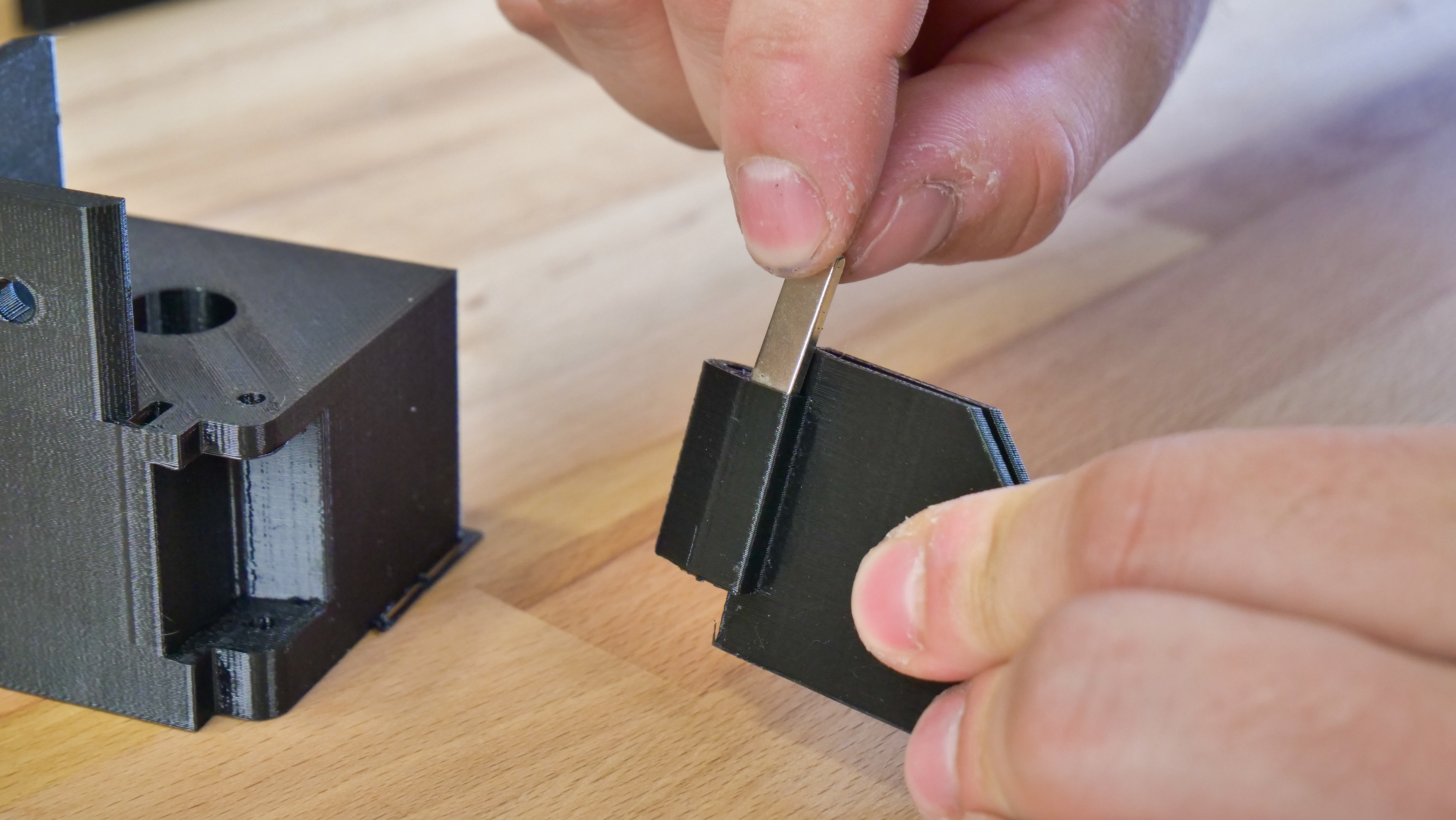
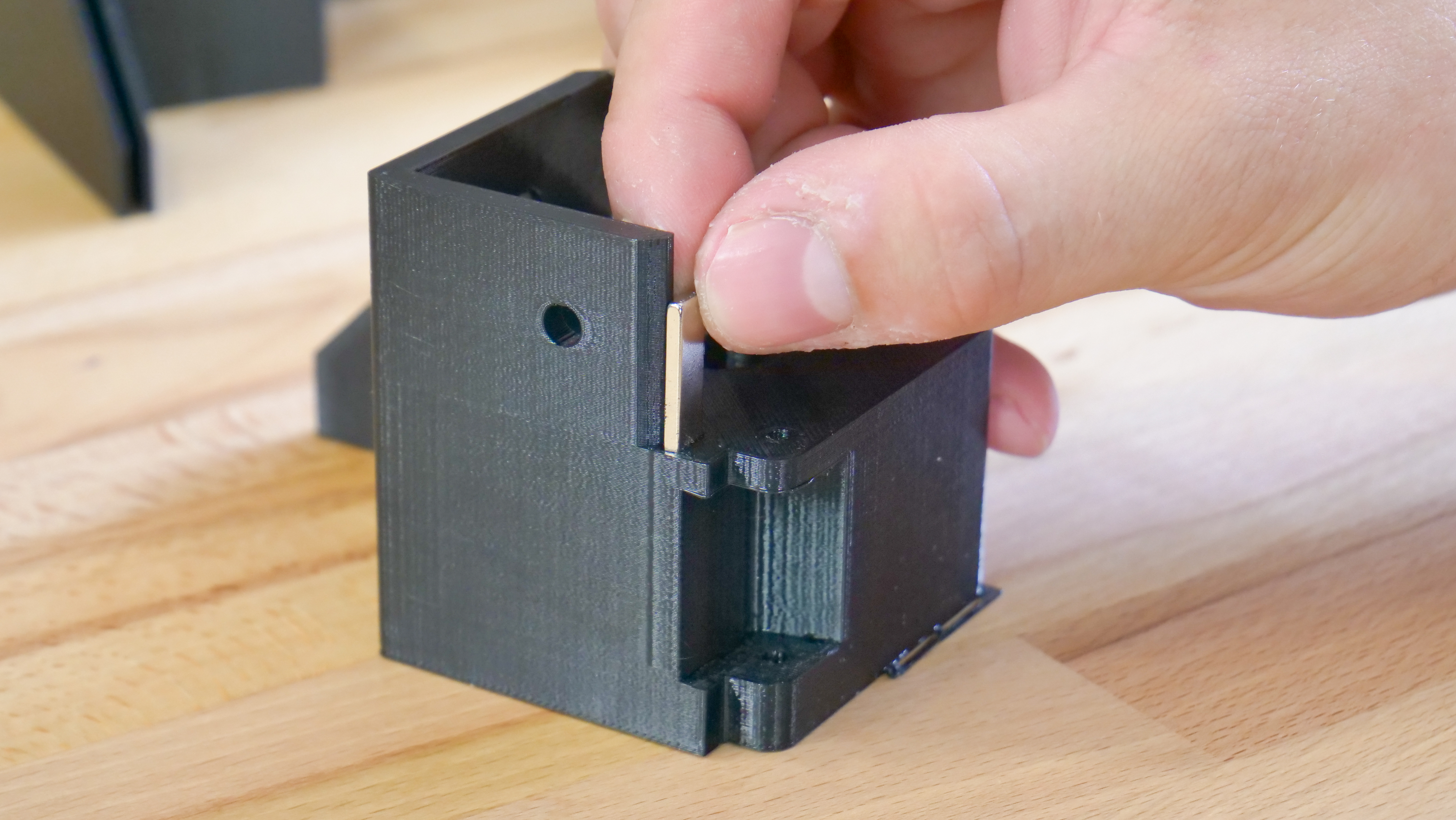
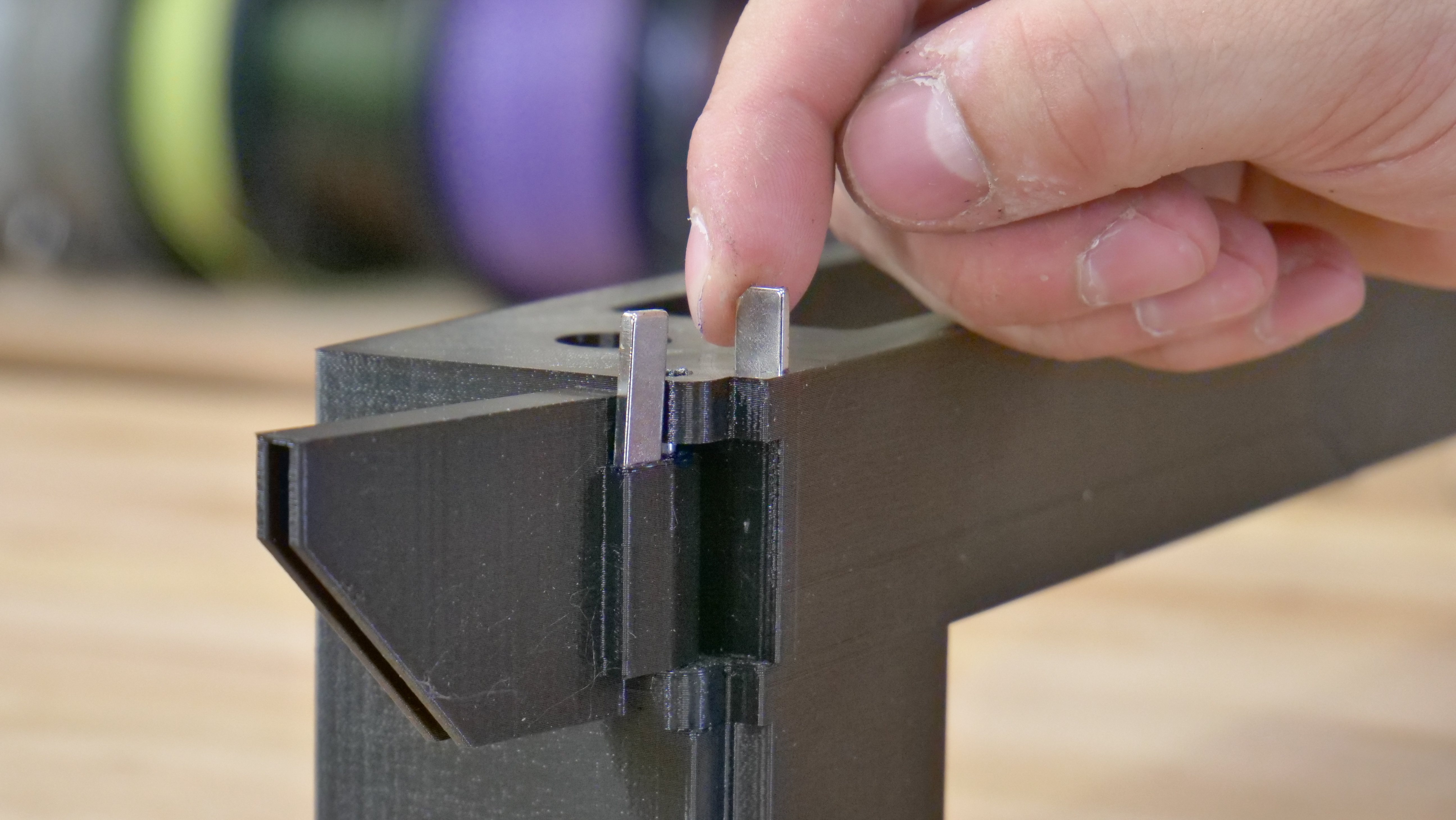
Place neodymium magnets in the front corners and attach the hinge to the corner part with an M3×30 screw. Assemble the frame on the ground, then flip it upside down. Sides are secured by 4 pieces screws M3 x 30 and the back side is screwed by two pieces of M3 x 10. Exercise caution when moving the frame around, so you don’t damage the printed parts.
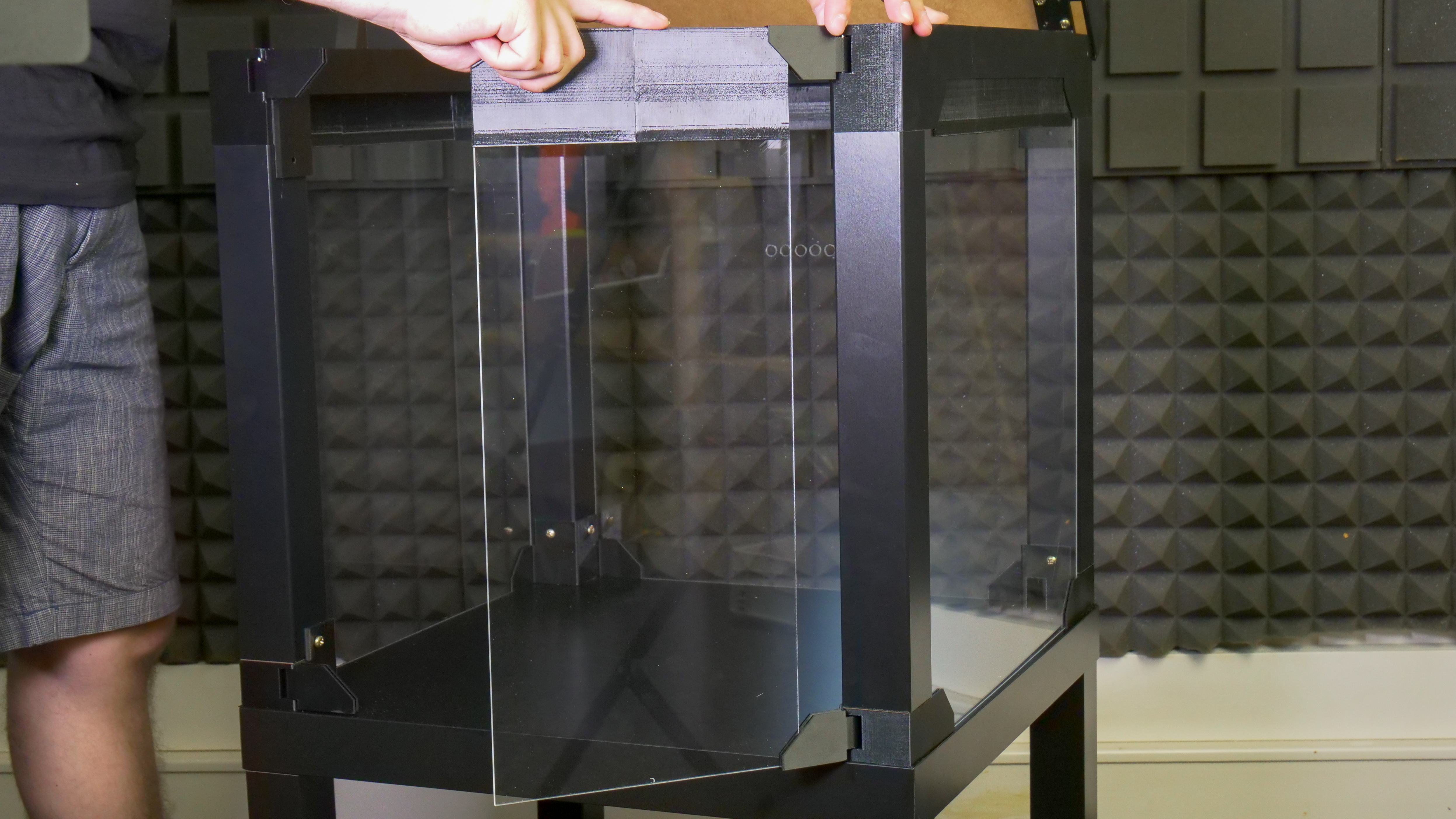
Attaching the acrylic sheet windows and the U-frame
List of printed parts for this step:
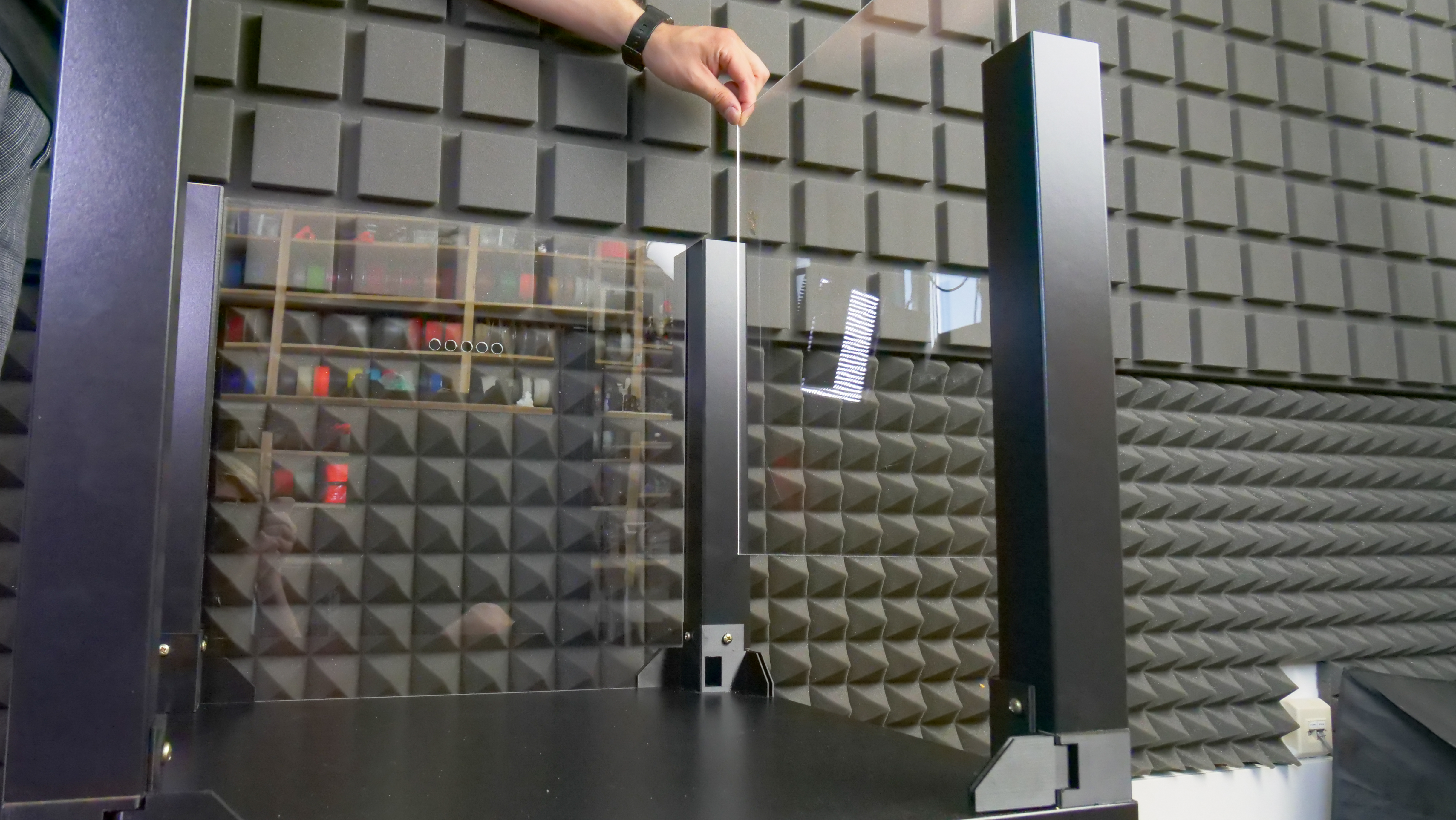
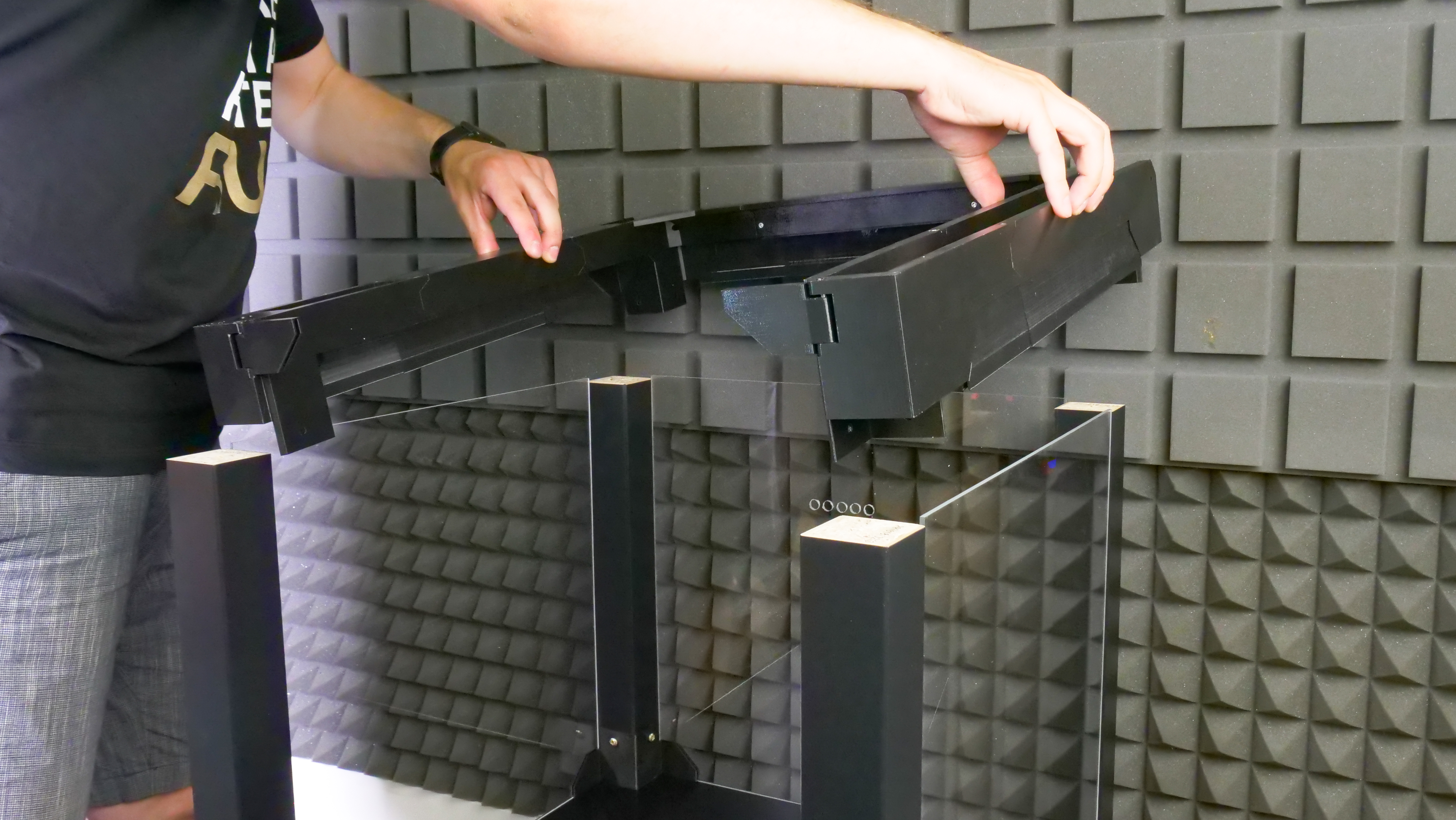

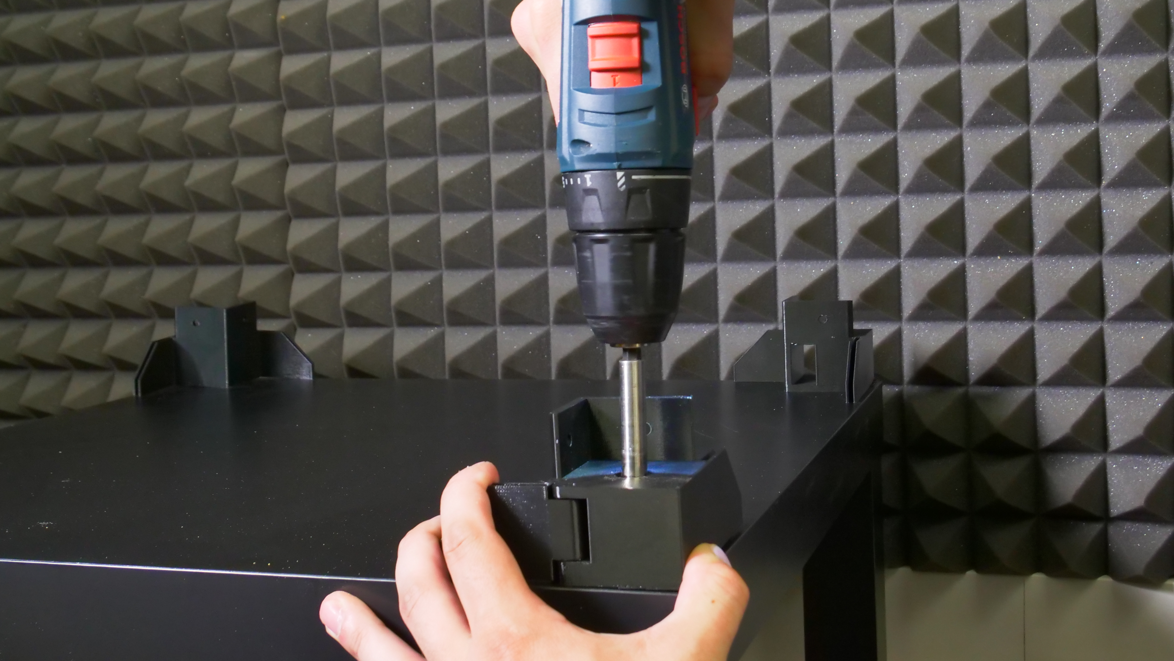
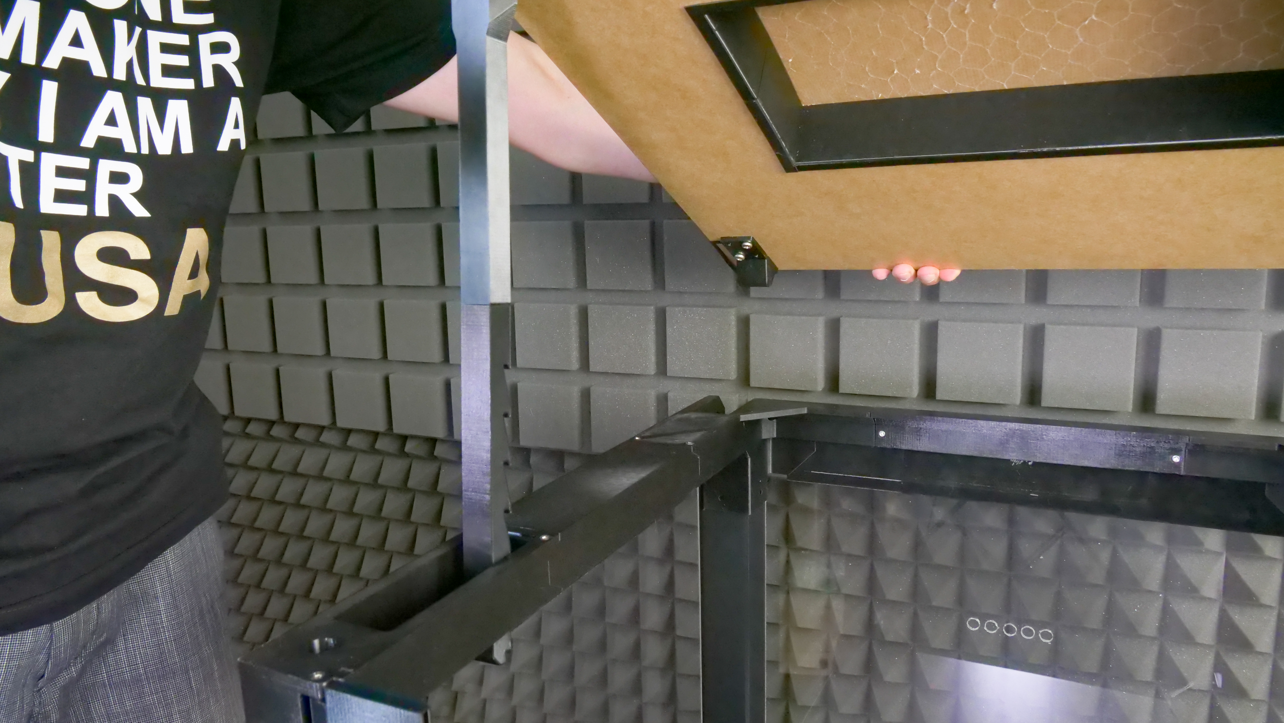
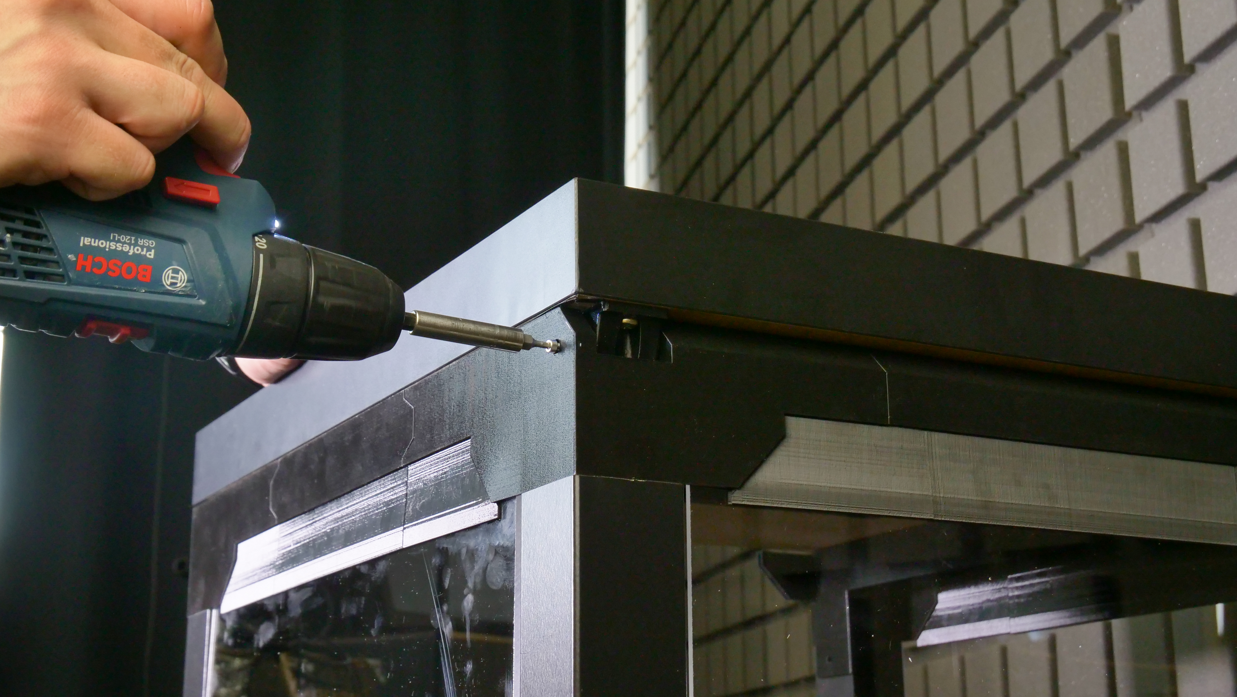
If you have the acrylic glass sheets in 440×440mm dimensions, start by attaching the extensions to the U-frame. If you have new clear acrylic sheets (440×473 mm), you won’t need the extensions. Insert the rear and side acrylic sheets between the legs of the upper table. Make sure the rear window has the five holes for PTFE tubes in its upper part. Finally, attach the U-frame onto the top of the enclosure. Each corner part must be secured with a 6×50mm screw (from the top). Optionally, it’s possible to secure the frame from the inside using two 5×20mm screws.
Attaching the top cover
Insert the supporting arm into the hole in the left top corner and place the cover (desk top) onto the enclosure.There are two openings for two M3×18mm screws on the sides. After you tighten these screws, you can open the cover and add two more screws from the inside.

Attaching the door panels
List of printed parts required for this step:
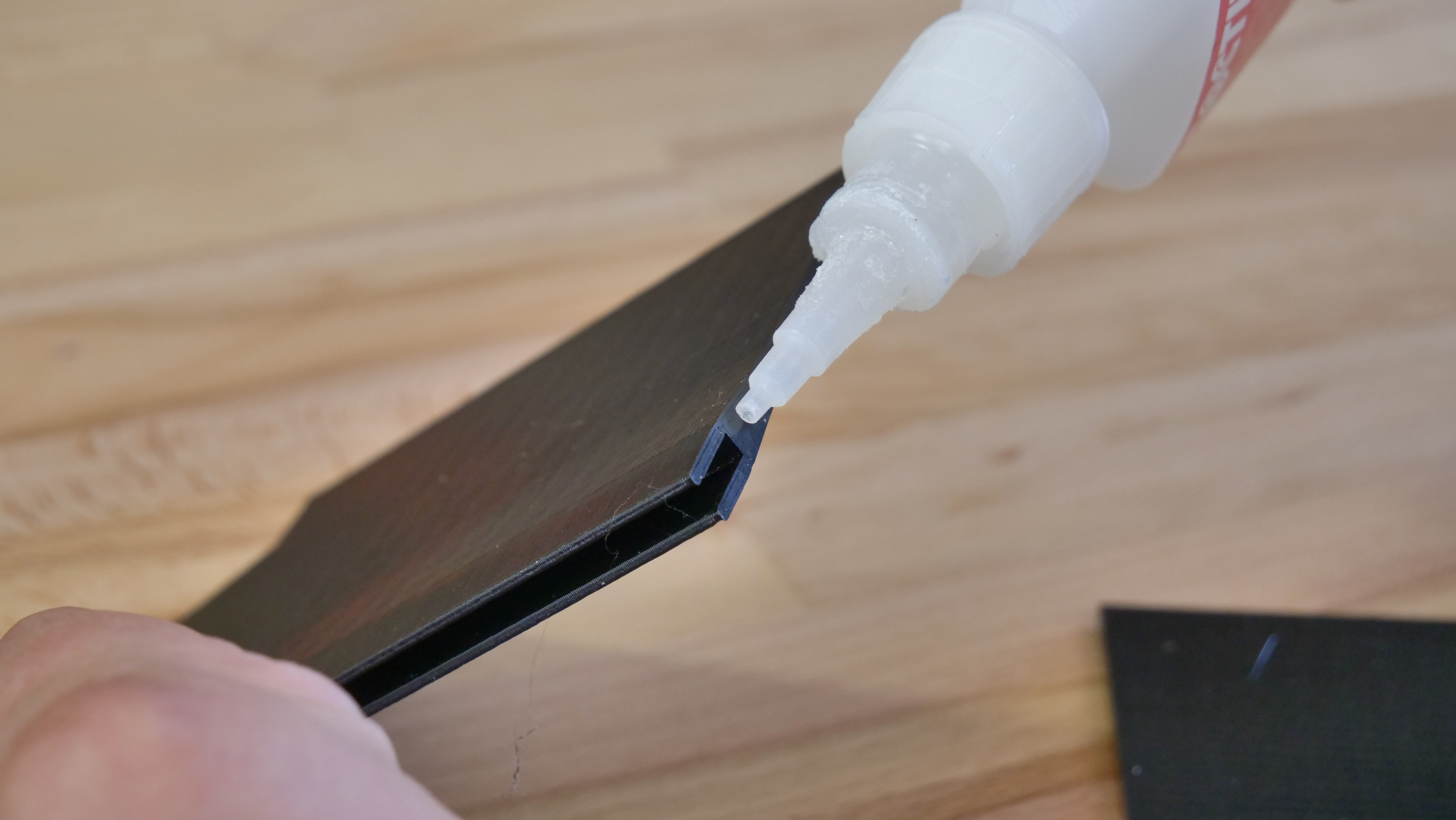
First, attach the extensions onto the door panels, then insert the acrylic sheets into the hinges. Optionally, use superglue to secure the parts.
Mounting the filament buffer and spoolholders
List of printed parts required for this step:
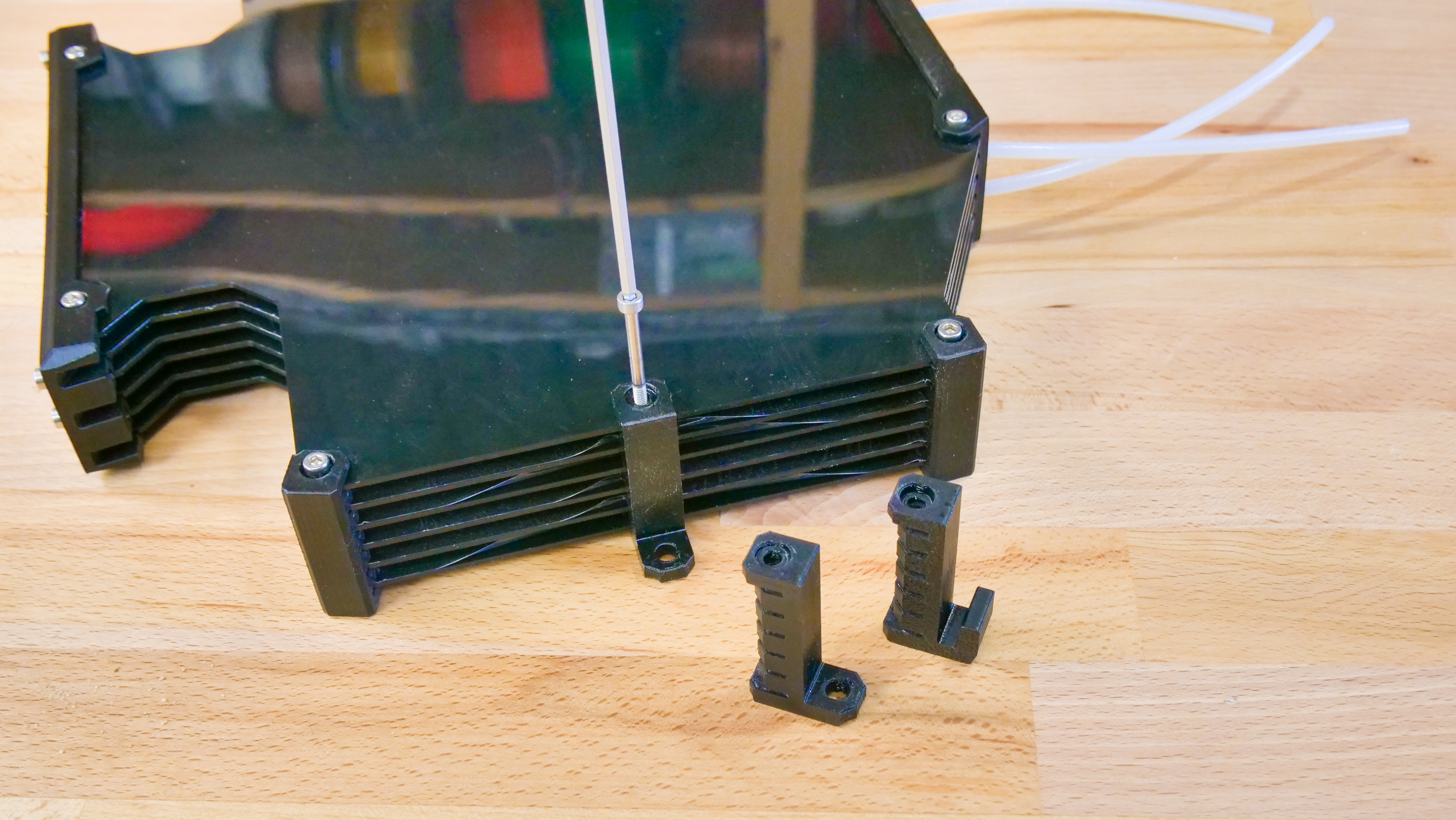
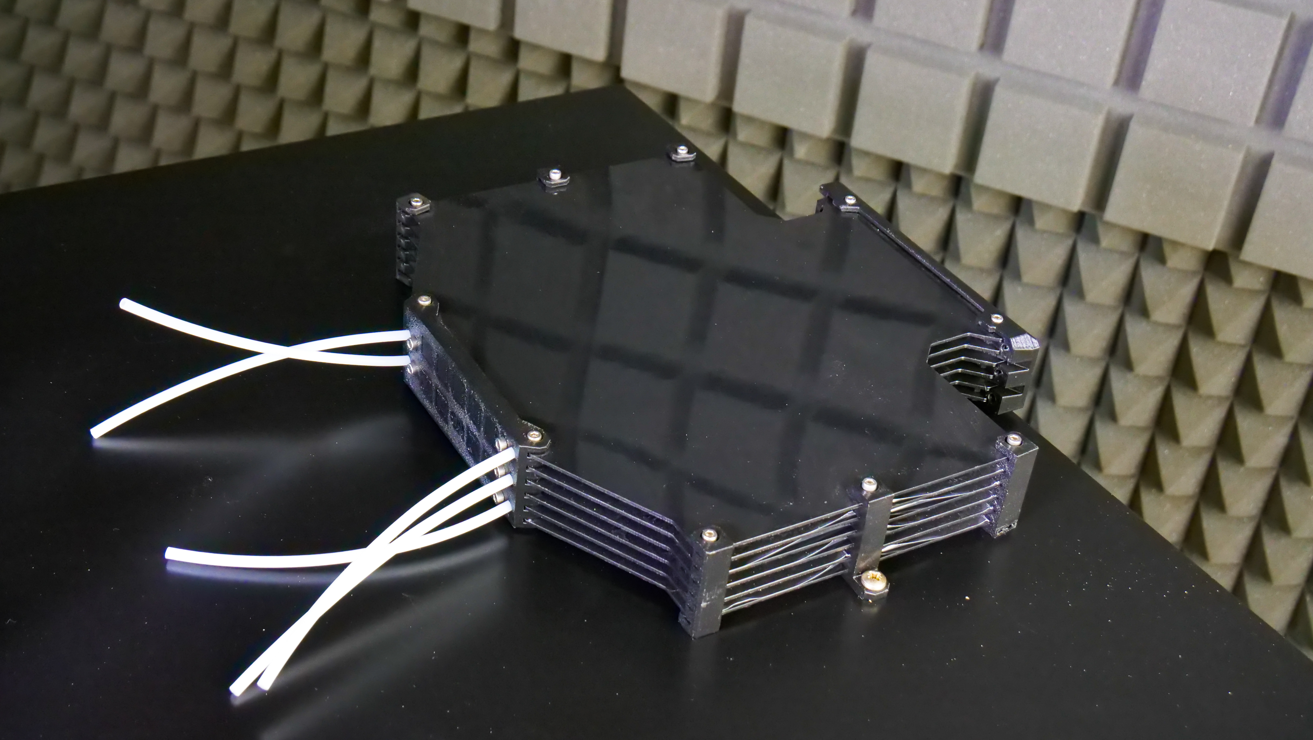
You will need to remove two spacers from the buffer (on the sides – see the photo above), these are called s-buffer-spacers. Replace them with the new printed versions (Prusa_MMU_enclosure_s-buffer-spacer). The modified buffer spacers have holes that are used to secure the buffer to the enclosure. Once you replace the spacers, place the buffer in the center of the top cover and align the rear edge of the buffer with the rear edge of the cover. Do not pull the PTFE tubes through the holes in the rear window yet.
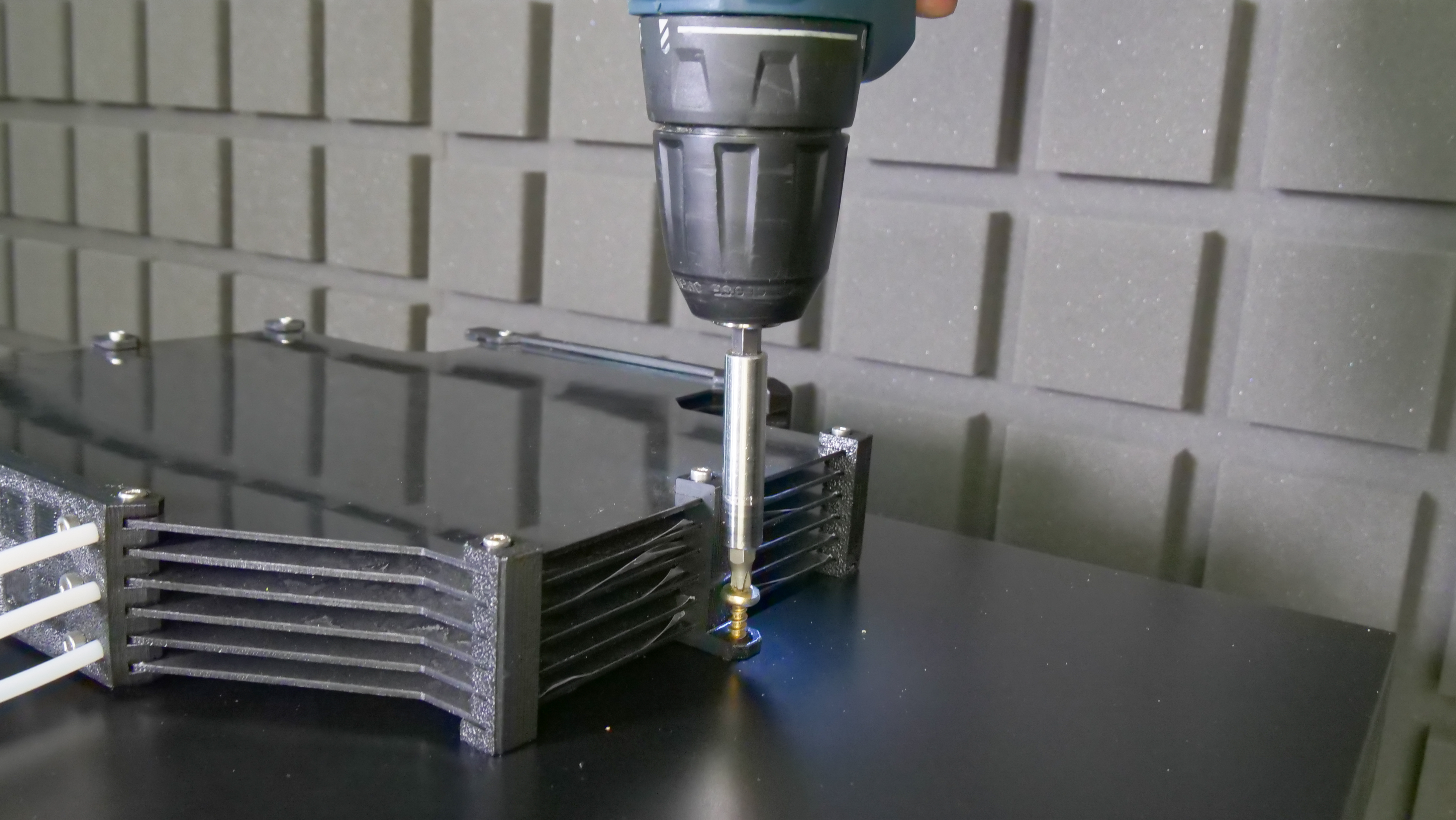
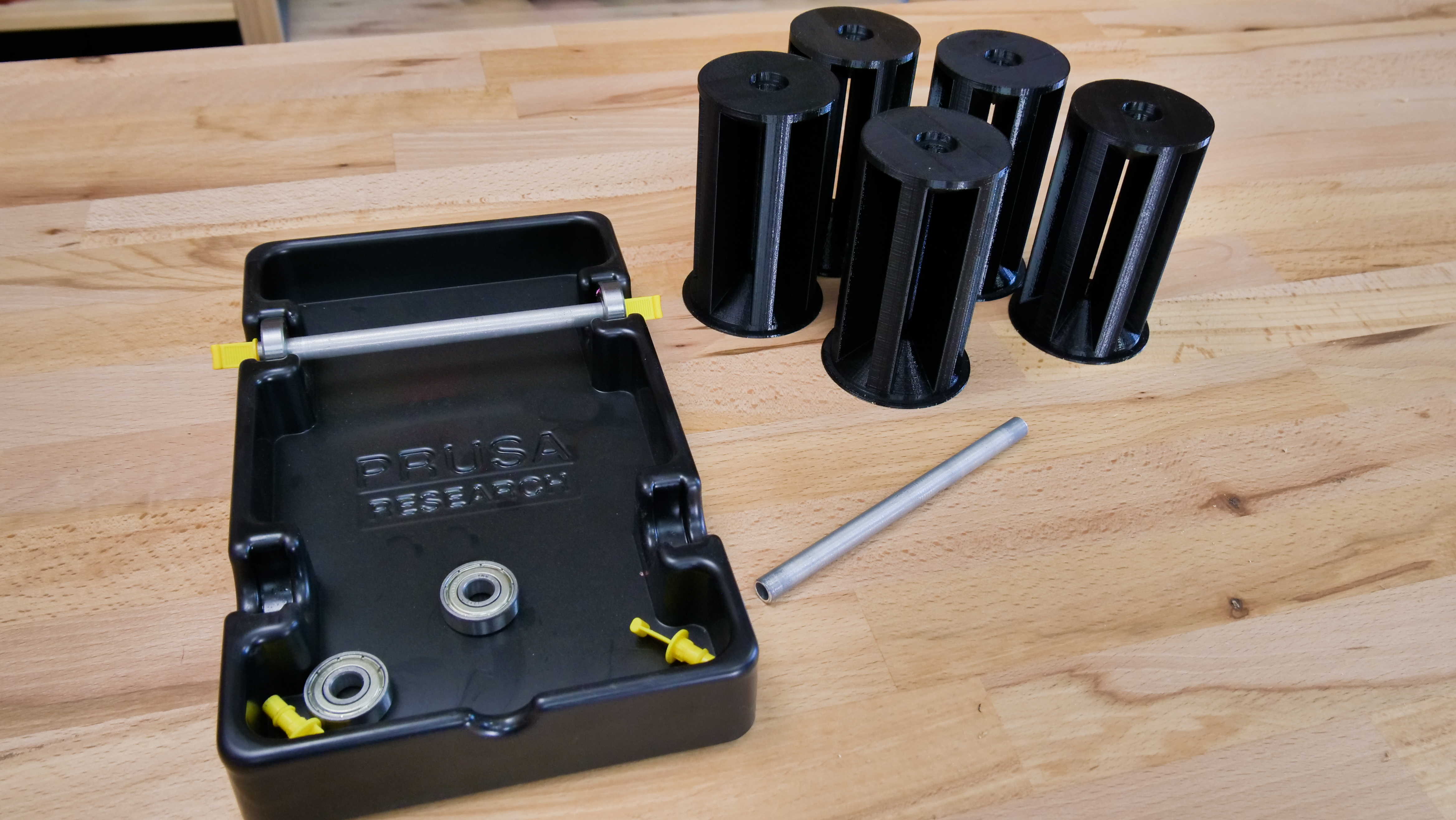
Next – the spoolholders. They consist of three parts. Place them 20 mm from the front edge of the top cover. Then use six 5×20 mm screws to secure them in place. Take the aluminum tubes/rods from the original spoolholders and insert them into the center of 3D printed cylindrical holders.
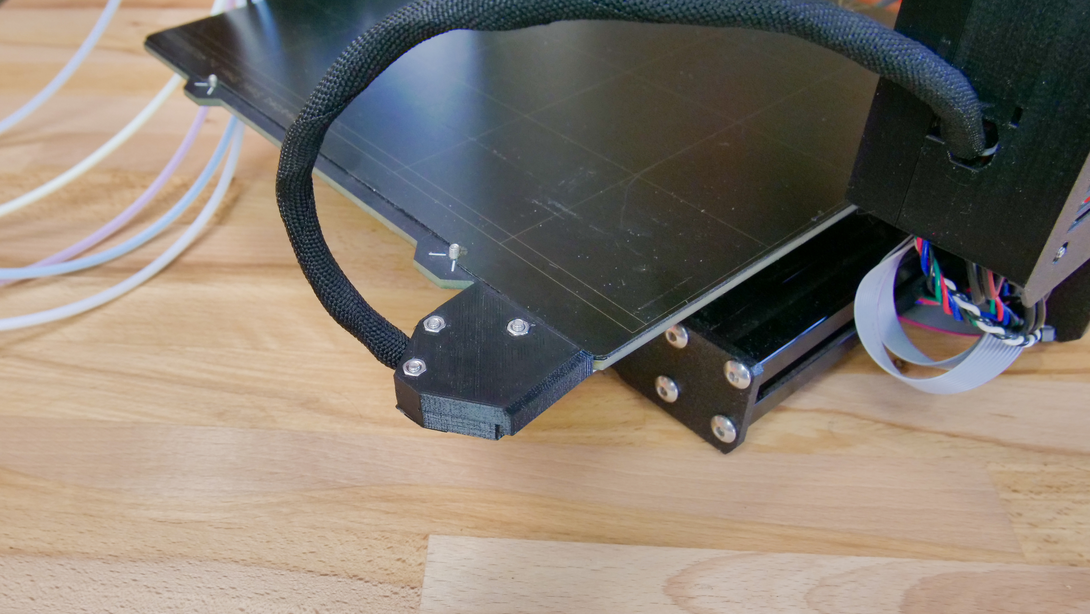
Alternate heatbed cable mount
Since the cables leading to the headbed can collide with the rear panel of the enclosure, we recommend switching the heatbed cable connector cover – the updated one will allow you to attach the cables under a 60-degree angle, saving some space in the back.
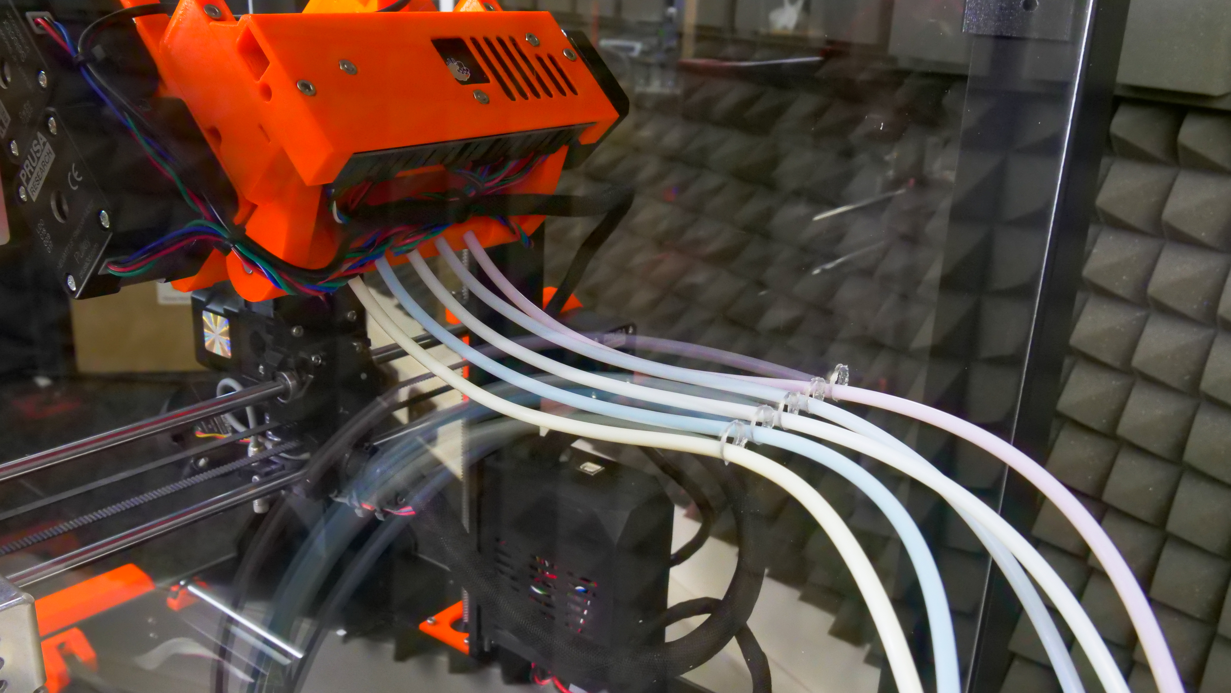
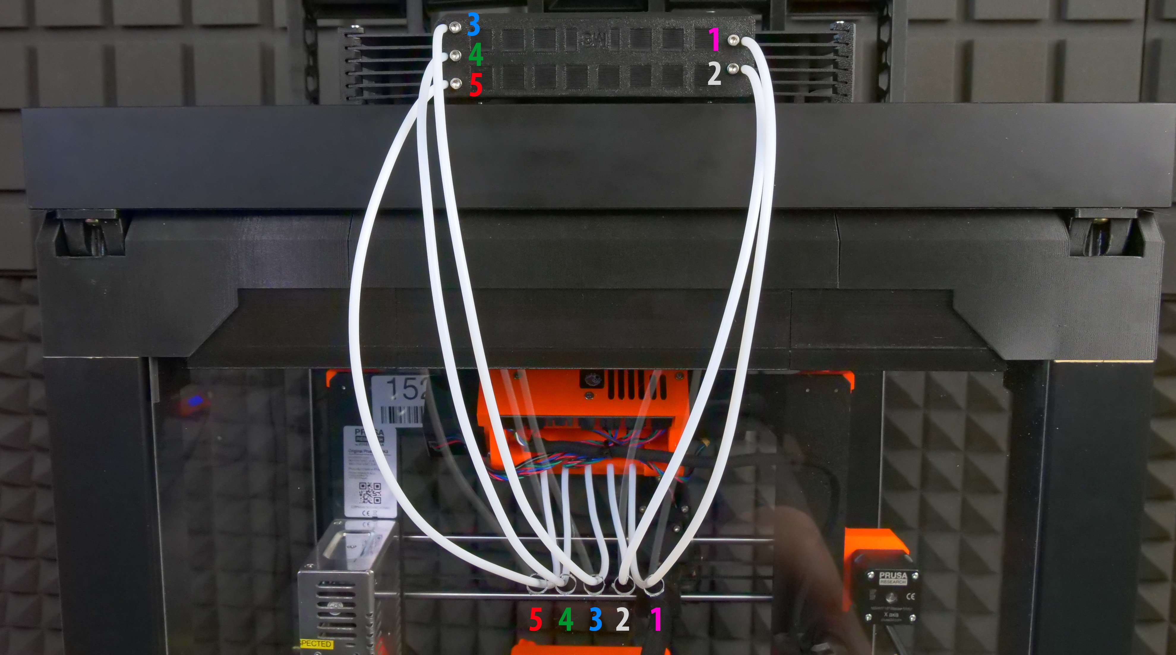
Placing the printer, attaching PTFE tubes
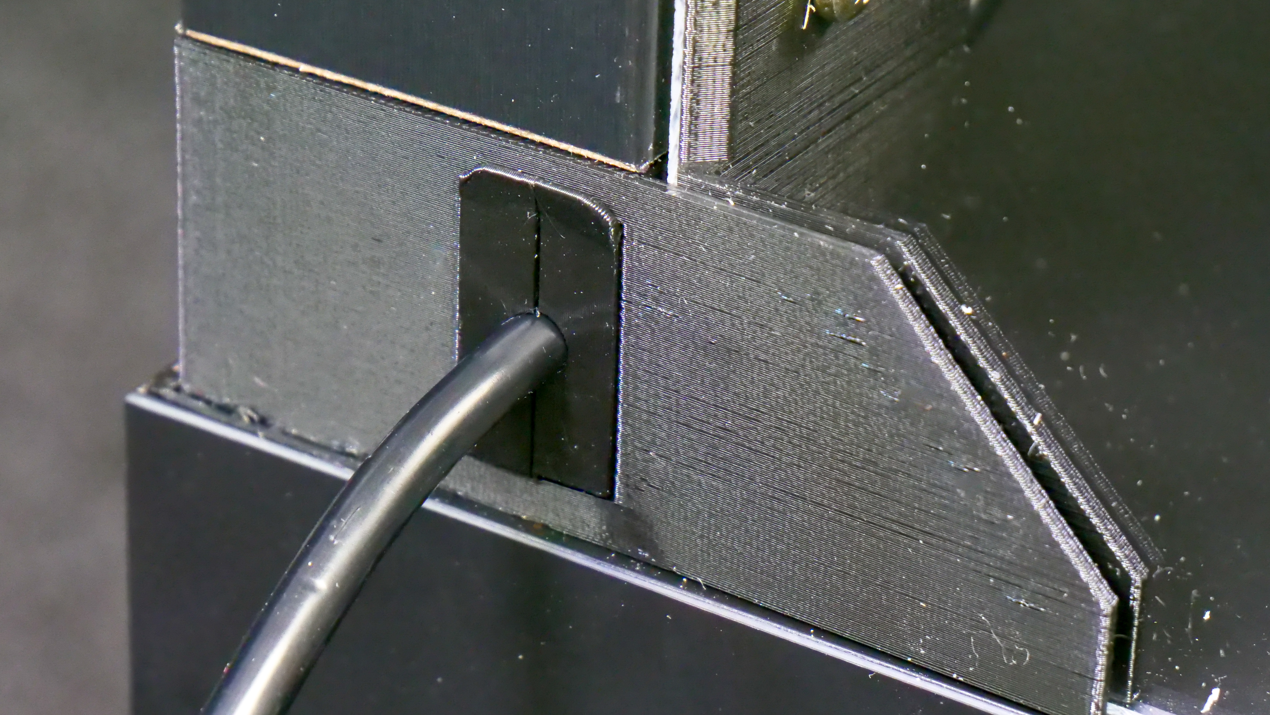
The printer should be placed in a position, where the front edge of the display case will double as a door stop. Open the top cover and pull the PTFE tubes through the holes in the rear panel in the order depicted in the photo below. Before you attach them to the MMU2S unit, take a sharp knife and shorten them by 115 mm. Be extremely careful not to damage/deform them. This could lead to serious issues with filament movement inside the tubes. The new length of the PTFE tubes should be 535 mm. Once this is done, attach the tubes into the MMU2S unit in the correct order – see photos below for reference. Don’t forget to add screws to stop them from detaching.

Power cable and cable bushing
List of printed parts required for this step:
1× Prusa_MMU_enclosure_cable_bushing
included in Prusa_MMU_enclosure_4.3mf
To ease the strain on the cable, we have designed a strain relief bushing. First, insert the power cable into the enclosure through the opening under right back leg and plug it into the printer. Then, bend the bushing in half, place it onto the cable and insert it into the hole.

Inserting filaments
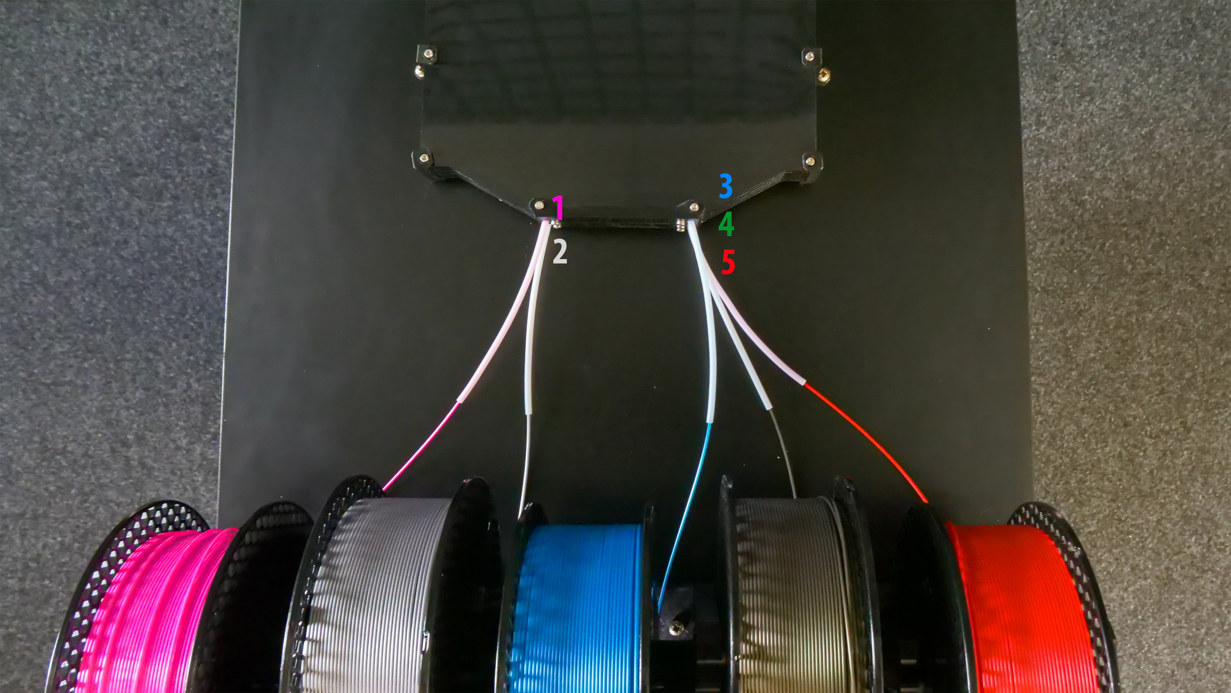
Insert filaments into the buffer in the order depicted in the photo below. 1 is top left, 2 is bottom left, 3 is top right, 4 is middle right and finally 5 is bottom right.
…and done!

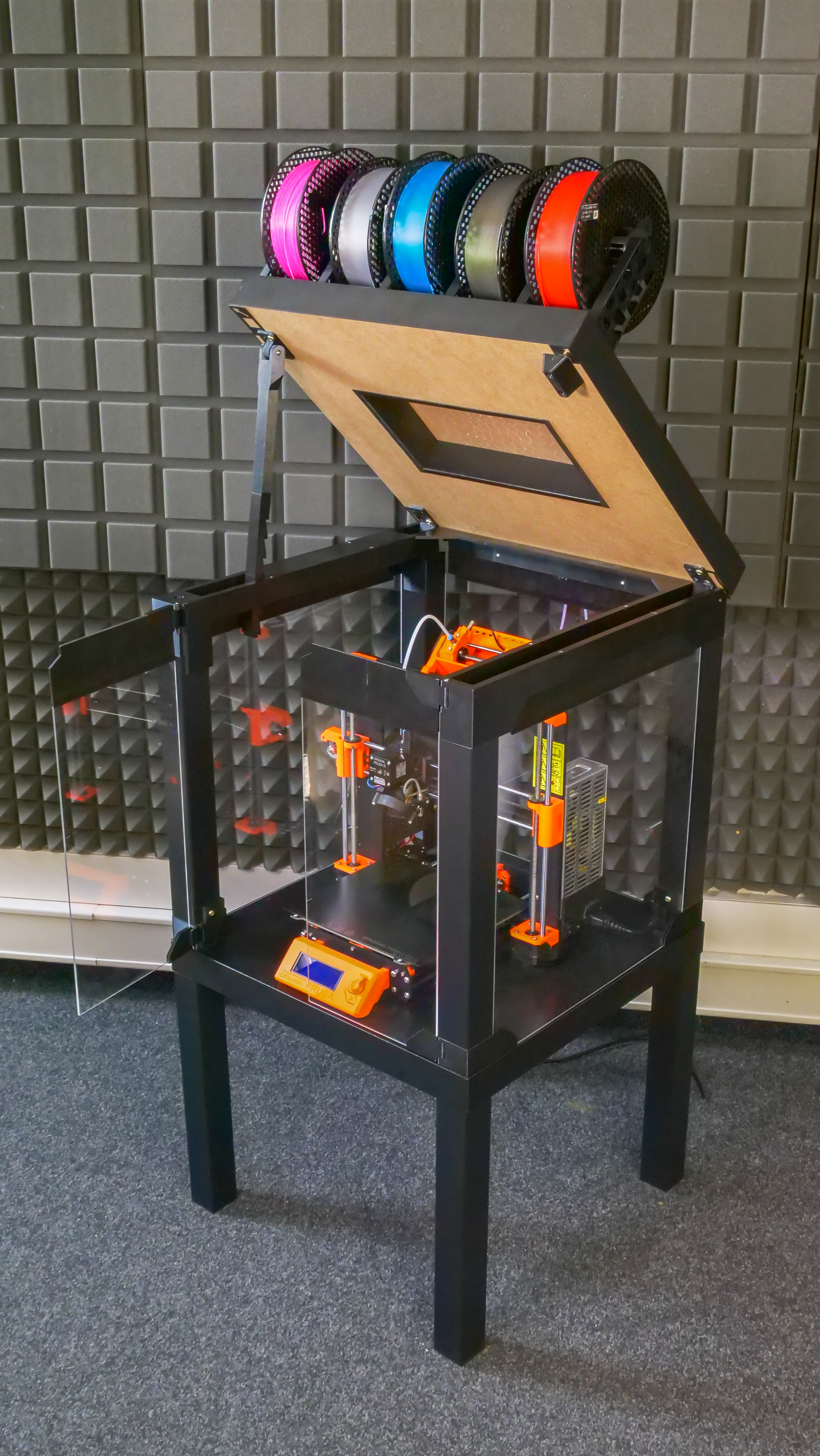
Now it’s time to find the best spot for the enclosure. One thing to keep in mind: place the enclosure at least 15 cm from the wall, otherwise the PTFE tubes won’t have enough room and they could deform. Insert the plug into the electrical socket and you can start printing! Great job!
And one more thing – you probably know that the MMU2S is great for printing soluble supports. These water-soluble materials (such as BVOH) are highly hygroscopic, though. They need to be kept in low-humidity environment, ideally even during printing. This is why we have designed a very simple, yet effective drybox. We’ll bring you a complete guide soon. Stay tuned!

Are you not removing the power supply like you did in the first version of this? Or did you just not add this step to this guide and we are meant to use both guides?
It is not being removed, and is visible still mounted to the printer frame in the last picture of the finished enclosure: https://blog.prusa3d.com/wp-content/uploads/2019/06/P1488090.jpg
was it decided that the temps inside the enclosure do not reach temperatures that could negatively impact the life of the PSU?
Would love to find out too from PRUSA or the community. Is the new PSU better at handling high temperature? Is this still needed?
How about the LCD panel and motherboard? Should that also be moved?
Just noticed they have a whole step just for the power cable.
I never moved my PSU. The wires were not long enough. After testing while printing a 24 hour ABS project, the enclosure never got hot enough to be a concern. If I remember correctly it reached 40c and the original PSU was rated for much hotter than that.
Prusa probably realized the same thing after testing.
There is a step about whether or not you need to place it outside or not.
Check on the article : “Placing the Power supply”
I left my power supply inside the enclosure as per this guide and… 45 minutes into printing, my printer shut down.. I was like wtf!!?? maybe I turned off the power strip by accident.. did a few checks and NOPE! The power supply BLEW! or whatever the hell happened! I wish Prusa would replace it, I’m still down. I am going to email them and ask for some support.
Can’t wait to get printing on this one, I really appreciate the effort of maintaining the sizes of the acrylic sheets from the original enclosure. Thumbs up!
If using the new larger acrylic, and therefore don’t need the extensions, how do you open the door since the door extensions have the finger notch built in to it?
If you use new larger acrylic, you have to cut off the corners.
Can you specify how much to cut off the corners? I was looking at getting mine printer plexiglass laser cut, so I will need to know beforehand.
I would also like to know this as I thought purchasing the new acrylic was the better option.
I would like this info as well
I will try to use the handles from the enclosure v1 (https://blog.prusa3d.com/cheap-simple-3d-printer-enclosure/)
Sir, Can you please help me. I have ordered all the plexi and needed parts for this project. I have been printing for several days only to have lost filament and parts. I am printing on a DaVinci Pro until my Prusa arrives later today. I was trying to get ahead with printing the enclosure. The mmu_ enclosure_1-2.STL forms a hard block around the hinge which is impossible to remove without breaking the hinge mount. Is there something I’m missing here?
Thanks in advance !
Ricky
I know it’s an old thread but just in case anyone else is wondering. If you import the 3mf files into slicers other than PrusaSlicer, the support enablers turn into solid components of the model and thus screw up everything. Only fix I see is to delete them in PrusaSlicer, export the new STLs, and then create custom supports in the slicer of your choice.
You can also try these. I designed them to solve that very problem:
https://www.prusaprinters.org/prints/5157-door-handles-for-prusa-printer-enclosure-v2
I used the handles and magnetic catch from V1 of the enclosure. The magnets in the hinges of V2 just don’t close positively enough for my liking.
As always this is some high quality info and Good Job Prusa!
I now have my weekend printing project and getting to use the plexiglass from the earlier version is so key.
now I just have to purchase an MMU v2!
jhbinfla,
WOW you really have long weekends. The print jobs alone without stopping is 160.9 hours or 6.7 days. My weekends are only 72 hours or so. LOL
RAH
Well, I already have an enclosure built, so i do not need all the items, but you are right, it will take two weekends to print them all…
Thanks PRUSA for this.
Does anyone have a simple extraction fan/hepca filter guide?
I would like to know this as well
I don’t have a guide, especially since I’m still printing parts to build the enclosure, but I think the hardest part is finding the smallest possible replaceable/renewable filter that will still capture the fumes. Probably something with activated carbon. The first thing that comes to mind is a “premium” automotive cabin filter since they’re already in a drop-in format. Maybe something with a small array of muffin fans in a second cutout behind the one for the PTFE tube on the MMU2s, so that it pulls the hot air and fumes through a cabin filter that’s tucked into that second cutout, and then through the muffin fans to the exterior.
https://www.thingiverse.com/thing:4146142
Hi,
I basically want to use the enclosure for organizing the buffer en fillament as it takes up to much space right now. Is it possible to build this without the plexiglass? Would that compromise rigidity?
T.i.a.
Kaan,
Plexiglas/Acrylic sheets are not used as part of the structure. I don’t see why you want to build an enclosure without the enclosure. The filament buffer is attached to the top rear of the enclosure taking up no real space as the spools are right in front of it.
RAH
Ondrej,
Could you please provide the parameters you used to build the GCODE files? Some of the provided ones print too long for me to use as is. I would like to split up some of the print tasks.
Thank you,
Robin
Slicing parameters are included in the .3mf file. So download .3mf, open it in the PrusaSlicer, separate objects into more build plates and export gcode. The print parameters are the same as default Prusament PETG with 10% infill and some custom support enforcers.
Ondrej,
Thank you. I was editing in another app and losing the details. I am getting much better results using Prusa Slicer and 10% infill.
Thank you,
Robin
Thumbnails 1 to 10 for .STL and GCODE – HERE:
https://www.dropbox.com/s/8vzknb2lme68eet/IKEA-LACK-MMU2S%20enclosure-pictures.rar?dl=0
Prusa feel free to add them to the download file!
Thank you so much, I used some of them 🙂
Why not an enclosure integrated with the printer??? I find this too complicated and way bigger than the printing area! 60x60x60 cm for 20x25cm of printing area takes way too much space! Sorry Prusa! I wait for an MK4 with enclosure out of the box!
Uhhh… this is a bit disingenuous. While the print surface may be 25cm x 21cm, that print surface has to move back and forth. The footprint of the MK3 is approximately 43cm x 53cm. The footprint of the Lack table is 55cm x 55cm. The increase in depth is insignificant, while the increase in width is about 21%.
However, if you have the MMU2 upgrade, the footprint of the printer and filament spools is significantly larger. I’m currently using a 130cm x 60cm space. I’ve seen the width of filament spools vary between 6.5cm and 9cm. So, to get 5 spools side by side would require at least 45cm plus some separation.
Perhaps this isn’t a space saver for those without the MMU2 upgrade, but I love it for compacting the foot print of space used for multi-material printing!
You’ll be waiting a long time. Someone has a patent that prevents people from selling enclosures… which is why you won’t see any printer manufacturer selling enclosures for their printers.
That’d be Stratasys you’re referring to. They used to hold a patent on heated build chambers, but that expired in February 2021. Yay!
Thank you very much for this enclosure! I waited for this since i got the MMU2.
But… The filenames are a little bit confusing. *….enclosure_5….* should run 4h42m. The filename suggested it. But for real the print runs more than 20h.
I don´t wanted the printer to run over night… but now.,…. 🙁
But it is just a small negativ aspect.
Kind regards! Phil
Thanks for the information. I corrected it.
I have the i3- MK3S, and I am finishing off the the up grades. But the problem is I am unable to build this, is there any one out there who could build this for ma and at what cost. I live in Southern California and would pay all shipping costs, is there anyone that can do this or knows someone who could do this?.
my e-mail address is [email protected] . Hope to hear from someone Thanks
Dowrad,
Did you realize that the GCODE files are for the i3 MK3(s) and you can do them yourself once your upgrades are complete?
Did you also realize that you are asking someone to use their printer for 260.7 hours to print the 10 files?
Just saying,
Robin
Print time is 160.95 I mistyped.
what if I just print the parts using my i3-MK3 build the enclosure and then install the upgrades, is there a reason I can’t do it this way. I found someone to assist me in building the table I just need to print the parts using my current printer that is working fine, thank you for your help. One the last note, any knowledge of a company that I can order the acrylic from in the USA.
thanks again, Dowrad
PrintedSolid.com sells precut plexiglass sheets for the enclosure if you are in the USA. It was $50 and free shipping when I purchased mine last year. High quality and nicely cut and they fit without issue.
Printed Solid has put out a new set of sheets for v2, including laser cut holes! https://www.printedsolid.com/products/v2-acrylic-sheets-for-prusa-lack-enclosure
Imperial measurements for acrylic sheets are in increments of .125 inches from the vendor I’d like to purchase it from. Is there enough tolerance in the frame to handle the .125 inch thickness? Also, for outside dimensions, should I round up or down when having the acrylic cut (again, .125 inch increments)
Just started printing the parts and will order the acrylic once I get a reply.
Great writeup!
Thank you,
Steve
Hi Steve,
the thickness of the plexiglass must be 3mm. Especially because of the front door hinges. (0.125 inches is 3.175mm and it is too much) I will recommend round up the outside dimensions because the printed corners are mounted offseted 2mm inwards, so you can eventually move them a little bit. Also between table legs and plexiglass is about 5mm tolerance in sum.
Thank you for the quick and detailed response. I think that I’ll check for another supplier that has metric standards and pay the difference to ensure I get exactly what I need.
On a side note, the spool holder design for the five spools should be highlighted in a separate article by itself. For people that do not need the whole enclosure but want more control of the spools this is a perfect option. Just screw it to a wall or down to a board. I’m printing these first.
Thank you for this great guide!
I have a question due to the magnets. Are also the 20×5×2 (1mm less in width) mm magnets possible ? Because these are much easier to get for me.
Yes, you can use smaller without a problem. Maybe just fix them inside the hole by the glue.
I bought that same size of magnet and found that I could fix them in place by stuff an inch or so of filament down the side. It was a tight fit so it holds the magnet perfectly in place.
Anyone know of a vendor in the USA that can cut to order the metric acrylic parts that are needed?
thanks, Dowrad
TAP Plastic uses metric sized sheets, but calls them out as imperial (i.e. their 1/8″ sheet is actually 0.12″, which is 3mm)
Not sure if I’m allowed to post a URL here, but I’ll try: https://www.tapplastics.com/product/plastics/cut_to_size_plastic/acrylic_sheets_clear/508
When you order from there you can switch the units to mm so there is no confusion, just ordered my pieces today.
Did you get any of their polished edge options? The hole option seems really worth it at $2 per hole. Much better than accidentally scuffing it up yourself.
Hi when I select metric there is only 2.5mm as an option. This won’t work, correct?
Select “extruded acrylic sheet” from the Tap Plastics “cut to size plastic” section and when you choose mm for the units, you will see 3mm listed for a thickness in the drop down. Posting for anyone else with this question coming to the page as this question is over a year old. PS: The extruded acrylic sheet is the chapest option available from Tap Plastics.
Printed Solid sells the acrylic sheets as a set with the holes pre-drilled.
https://www.printedsolid.com/products/v2-acrylic-sheets-for-prusa-lack-enclosure
Can i use the table from the first enclosure or must i buy a new one?
You can reuse the table of course. Only some old screw holes can be visible, but you can easily mask them with black electric tape.
No more LED strip? That’s a shame, I even found an interesting capacitive dc light switch to try and integrate.
Also any more than 6cm away from the wall and the printer enclosure would be getting in the way. Plus I have a big dry box already and won’t be using the spool holders. An alternate design where the PTFE tubes come in from somewhere other than the back would be preferred. Whether they come in from below, the side, or the top.
Thanks for the great design and write-up. My MK3S and MMU2S are on order and I’ve already been ordering the other parts required for this enclosure while I’m patiently (sort of) waiting for the the MMU2S backorder log jam to break free. I started to order fasteners from McMaster-Carr (metric hardware is a little harder to find at a US Lowes) and I noticed a few small inconsistencies. Forgive me if this comes off as nit-picky. Looking at the models I believe I figured out the intent and wanted to share in case it helps out someone else or in case I’m just confused you can set me straight:
1) In your list of fasteners, you have 35x flat-head 5x20mm screws. I believe these should be pan head 5×20 screws (flat bottom, not flat top).
2) In the “Assembling the U-frame” section, it calls out M3X10 screws to assemble the hinge to the corner parts. I believe these should be M3X30 screws.
3) The top and bottom corner parts are fastened through the same sized 6mm dia holes with 14mm dia counterbores in the center of the part. In the “Building the box – lower table” section, the bottom corners are called out to be secured with 5x30mm screws and in the “Attaching the acrylic sheet windows and the U-frame” section, the top corners are called out to be secured with 6x50mm screws. It seems to me that both the top and bottom corner parts should be secured with 6mm dia screws if sticking with the design precedent that the hole and screw diameters are to be a line-to-line fit.
Hi Jonathan, thank you for comments. I have checked it and fixed it. Enjoy your build! 🙂
If you could provide a McMaster-Carr part list for screws it would be greatly appreciated!
I placed my order with McMaster-Carr last night. So I haven’t received it yet and I can’t yet tell you how well they work out. So use this list at your own risk…
1) for the 5X20mm screws:
P/N: 92470A245, #10 X 3/4″ SS Round Head Sheet Metal Screws, 100 pack
2) for the 6X30 and 6X50 screws:
P/N: 92470A319, #14 X 2″ SS Round Head Sheet Metal Screws, 25 pack (The bottom corner pieces don’t need screws that long but the thickness of the Lack table top should accommodate the longer ones so I didn’t see the sense in buying a whole pack of a different size)
3) for the M3X30mm screws:
P/N: 91292A022, M3x.5mm X 30mm long SS Socket Head Screws, 50 pack (closest English equivalent wasn’t close enough IMO and these were readily available)
4) for the M3X18mm screws:
P/N: 91292A029, M3x.5mm X 18mm long SS Socket Head Screws, 100 pack (closest English equivalent wasn’t close enough IMO and these were readily available)
5) for the M3X10mm screws:
P/N: 91292A113, M3x.5mm X 10mm long SS Socket Head Screws, 100 pack (closest English equivalent wasn’t close enough IMO and these were readily available)
Grand total: 30.47 USD (before tax and shipping)
Thank you this is very helpful!
Thank you so much. This saved me a lot of time.
BTW, be careful to double check both part numbers and description. It is easy to type in the part number wrong. (Not that I did, of course.)
The 2 inch screws DO NOT work for attaching the bottom corners to the table. They are so long they hit the bottom table metal screws and it throws off everything. The 30mm screws or English equivalent are definitely needed!
Using 2″ screws to attach to the bottom table isn’t going to work. You’ll hit the fasteners that IKEA uses for attaching the legs. But if you didn’t use the IKEA fasteners, then 4″ or 5″ screws should work fine. I am thinking of something like: https://smile.amazon.com/Extra-Long-Screw-Drive-Pound/dp/B07ZWHJM39
#14 1 3/4 oddly worked perfectly. Being a touch too big for the hole had its advantages. Allowed me to tighten as far as I needed and then spin the corner piece down tight.
The m3x30 you selected (see: 91292A022) is the partially threaded screw. Was this intentional? I ended up selecting the fully threaded m3x30 screw (see: 92005A132).
Alternatively, can go the US #4 sized screw which is 0.112 in versus the metric M3 which is 0.11811 in (pretty close). (see: 90190A125)
Sorry for the delayed response. I think I chose the partially threaded only because that’s what was in Prusa’s hardware picture. It worked out fine, but I imagine fully threaded would work just as well.
It looks great, can’t wait to get it together and get the printer off my computer desk.
Using the provided gcode I started printing on my MK3s yesterday.
I tried to “Secure the hinges with M3×30 screws” but the screw doesn’t grip on the other side and just pushes all the way through. Should I have left the supports in the holes?
I just glued them in place. I doubt I will ever have to undo them.
Yeah what the heck! I had this same problem. Maybe they accidentally messed up the dimensions of the hole with the 3.125mm acrylic sheet version? I guess I’ll just glue it in place like you did LOL.
I had the same, but then I realized that it catches if you push a screw in with a bit of force and wobble, then you can screw it in more
Instead of glue, etc., I printed a pair of “plugs” that are flush with the bottom of the corner bottom hinge pieces. The plugs fit tightly and assuredly will not move when the whole piece is screwed to the Lack table!
https://www.prusaprinters.org/prints/29680-lower-corner-hinge-plugs-for-prusa-enclosure-v2
Thanks @theheig
Recommend everyone use these plugs. I used glue to hold the screw in place and it has made my hinges much slower to open close (glue leaked into the hinge through the screw head). I plan to take it all a part, install new hinges and use these plugs. Would highly suggest Prusa add four of these to the build (bottom and top hinges).
Re: Holes for M3 x 30 hinge bolts
Thanks for those plugs. I had the same idea.
Though of course, better still, Prusa should the update the models/files with reduced top holes 😉
I made a ‘rawl plug’ from folding a small strip of single-layer print, inserting into the top hole. It is a faff, but I got it to grip sufficiently after a few attempts. The rawlplug also removes any slack. Drop of superglue won’t hurt.
I found it best to pre/trial fit the screw without the door part, holding the rawlplug in place from top, so you can see what’s happening as the bolt is screwed into the top hole. Then the full ‘blind’ assembly goes better (as the ‘thread’ is already partially cut in the ‘rawlplug’).
For the bottom, I might use some silicon just to be sure the bolt doesn’t loosen and drop in future.
** Extra Tip: what to do those cable-tie offcuts? 😉
I found they hold those pesky magnets in place quite well!! Insert by hand, with the magnets positioned inward, trim, push in flush using a flat hard object (end/side of pliers, ruler or similar). Should be removable (for when you realised one needs flipping!). Else, silicon or glue ’em in!?
excellent, works great!
In the US, it’s difficult to find [35× pan head screw, 5×20mm]. If anybody knows of an imperial equivalent that will work, I’d love to know.
The alternative is importing three hundred and throwing out 265 of them, which I’d like to avoid.
the metric 5x20mm screws are fairly close to our #10×3/4″ screws ( in works out to 4.826×19.05mm ) in the States.
Ace hardware sells #10 X 3/4 screws they are $0.14 each if you are in the USA.
Thanks to all with the info on the screws. Absolutely ridiculous that us Americans haven’t shed the bloody English units, drives me crazy. Absolutely can’t find “35× pan head screw, 5×20 mm” anywhere!
On a similar note, *Prusa*, thanks so much for designing this thing, but do you have any idea the number of hours we are all wasting scrambling around for these parts, please consider selling kits as well for those of us that would appreciate the convenience!
The image showing the fasteners needed does not seem to match the list provided. It also is not clickable so we can take a closer look. Would you please provide a higher resolution reference for the collection of fasteners for this project?
The image is just for reference. The list is important. For example, 4× screw 6×50mm at the image was replaced with 4× screw 6×30mm. The image in higher resolution is available now.
Awesome upgrade!
As I have a Lack table tower 🙂 I placed the printer on a 32mm stone slab to reduce vibrations. Is there enough space for the stone? Thanks!
It should go in there. But if you print maximal tall object, the PTFE tube could touch the roof table.
CUT OUT WARNING:
The hole is NOT symetrical and the measurements on the other side of the hole are MISSING to avoid confusion.
I royaly fucked up and is left with a 30mm gap as I measured 170x120mm all around the hole for the enclosure.
Unnecessary mistake if you could add the 550-170-180 = 200mm measurment on the other side indicating that the hole is NOT symetrical!
Thank you for improving the guide!
What holes are you referring to specifically? Thanks 🙂
The large square hold in the top bottom of the table. I’m still trying to figure out if I should cut it toward the back or front… hum…
Did you find out? What is the position and size of cutout?
Oh I was blind! It’s shown on one of the pictures … 🙂
I would love to know the measurement of the cutout in bottom of table. I know it says dimensions in pic , but I cannot see them. Too small for my eyes.Also placement would be good as it isn’t centered
Does anyone have an estimate of how much filament we need to print the parts (without the extensions, but I’m sure others would like to know including the extensions)?
I just want to know how many spools of PETG I should order?
If you check out the print on prusaprinters.org, you will see, that it is 2067 g. 🙂
Would you be able to add that to the list of what you need at the top? There have been several comments asking it and until now I didn’t know it showed that on the prusaprinters site with the files
I just finished this monster of a print almost 200 hours and 3 rolls of petg and all I need now are magnets. I’ll post pictures after it’s assembled
3x 1kg rolls, with or without extensions for the Plexi? I was afraid of that…I’m on the 6th file and my roll is looking a bit empty…… I already used maybe 100-200grams off an old spool I had.
I guess I should order at least one more. I’m not printing the spool holders thought as I already have a solution for that
I just finished printing file 5 and my first spool is near empty. It seems the full print is 2067g, so you should be fine with two if you are not printing the spool holders.
Our current setup has the filament spools on a shelf above the printer. That has caused a lot of problems with the trays. I’m looking forward to using the new filament holders. If you mount them on a shelf as I intend to do, you might want to turn the whole assembly around so the numbers are facing the wrong way, so that any pull on the spool pulls the hub into the holder not out of it.
We now have the spool holders mounted above the printer on a shelf. The orientation of the numbers does not matter, since the slots for the spools are angled both ways. I’m still printing without the MMU while I’m printing out parts for the enclosure, but the new spool holders work great. I still plan to mount the filament buffer as documented on the top of the enclosure and then feed the buffer from the spools on the shelf..
Apparently there are two different heatbed connectors, one a soldered version and another one a screwed version. There are two different versions of the 60 deg angle part. I found this out via a comment buried in the 60 deg part that this writeup refers to. I think an update is needed in the parts section with links to both parts.
The comment I found was from andredigital:
“the heatbed version with screws instead of soldered cables: https://www.thingiverse.com/thing:2964580 ”
Luckily I ran into this before I started to squeeze the wrong part on.
….still happily printing my other parts…..
Steve
Ooh, that saves me figuring that out myself – cheers for the link 🙂
Great call, I thank you very much! The one built for soldered connections won’t work… (personal experience)
Entered a LONG post with feedback –
“You are not logged in”
Post gone.
Can you fix that in the forum please.
(ARGH!)
I’m a metric challenged US citizen. Anyone able to help me out with conversion. I thought I could easily find these in my local hardware store and stood there lost for a good 20 minutes.
I’m also lost when I go to the hardware store in the states, even if I think I know what I need.
My internet search for conversion comes up with the following:
• 35× pan head screw, 5×20mm (pan head #10 3/4”)
• 4× screw 6×50mm (wood screw #12 2”)
• 4× screw 6×30mm (wood screw #12 1 1/4”)
I ordered the plexiglass through tapplastics (highlighted by other makers), they have a metric option for special size pieces. And I’ve ordered my magnets through umagnets since I wanted the exact size recommended.
https://www.umagnets.com/p/20mmx6mmx2mm-thick-neodymium-block-magnet-n35-thin-magnets-super-strong-rectangular-rare-earth-flat-magnets-20-x-6-x-2mm/
Still printing my parts………
Hope that helps,
Steve
Hah. I was just logging in to post this. Went into ACE the other day completely lost. Almost made a horribly incorrect order today until I found this conversion chart. I would have never known how to convert the diameters.
https://www.engineeringtoolbox.com/screws-metric-inches-equivalents-convert-conversions-d_2056.html
I ended up with:
4x #12 x 2″
4x #6 x 1-1/4
Box of #10 x 3/4″
12x M3x30
4x M3x10
4x M3x18
Thank you both for the help, I eventually converted and went with.
35x 5x20mm panhead or #10 x 3/4
4x 6x50mm or 12 x 2
4x 6×30 or 12 x 1 1/4
12x M3x30 or #4 x 1 1/4
4x M3x10 which I believe I found in store
4x M3x18 ordered from amazon since I could find 16 or 20 but not 18
I ran out of filament but the rest of the print has gone well. I am almost done thought, just have the filament holders and one of the corner prints to do.
Best of luck!
I highly recommend AGAINST shopping with Umagnet. I placed an order for these magnets on July 5, 2019 and still have not received the magnets. Today is July 24, 2019. They show as still sitting at LAX airport.
I wish I’d read this prior to placing an order with them 🙂
Thanks to everyone here for your help. I’ve also noticed that most of the M3-type screws, and even some magnets, are available among the spare parts from my printer & MMU.
Had I been paying attention, I wouldn’t have printed “Prusa_MMU_enclosure_8.3mf” for the plexiglass extensions since I don’t need them. However, having parts around that I don’t need violates my esthetic sense and it reminds me that I didn’t completely read and re-read the directions. 🙂 So, if anyone (living in the continental U.S.) would like a set of extensions (for the 0.125 inches (3.175 mm) thickness acrylic sheets), I will send them to you. I just need an address. They are made of purple PETG because I like purple.
Note that #12 wood screws are 5.5mm. They barely engage in the 5mm pre-drilled holes in the legs (where the upper frame is screwed into the tops of the legs). Be careful tightening with #12 screws, as they could strip the hole. #14 is closer to 6mm, but slightly over. I’m not sure if #14 will clear the original holes in the printed parts. #16 is the closest to the original IKEA screw that threads into the leg, but you will definitely have to enlarge the corresponding holes in the top frame before you print it if you want to use #16.
found the Neodymium Magnets 4x 20x6x2mmon etsy, great seller too;
https://www.etsy.com/listing/933269153/neodymium-magnets-4x-20x6x2mm-prusa-ikea
Here is a doorknob for the new larger size plexiglass, I modified the step file from the original enclosure and removed the magnets and doorstop since they are now built-in:
https://drive.google.com/drive/folders/1-6aVsYPAZ6UNKYhJpJgQ0h9rRYoeQt57?usp=sharing
Prusa feel free to use them.
I am using #14 x 2″ Round Head Sheet Metal Screws in place of the 6x30mm screws indicated. I’m finding these screws are a bit larger than the hole. As a result, when I screw them down, each of these blocks is tilted slightly toward the outer corner, leaving about a millimeter gap on the inside corner. Any suggestions as to how to fix this? I’m beginning to think I might have to drill out the PETG bottom corner parts to make this work.
You are more than likely hitting the bottom table leg fasteners with the 2 inch screws. Same thing happened to me. I cut some length off the 2 inch screws I bought and this fixed it.
I don’t have an MMU2 but I really like the spool holder design. Where can I get the aluminum rods? It says to use from the old spool holder. Is that something that comes with the MMU2?
Yes, it comes with MMU. Diameter is aproxiometly 7.7mm and length is 120mm. I think, that you can print it easily 😉
I didn’t have the spool rods either so I made some!
They work perfectly and I decided to share it whoever is in the same boat.
https://www.prusaprinters.org/prints/4592-mmu2-printer-enclosure-spool-rod
I was diligently following the build instructions and realized that the first picture in the step “Assembling the U-frame” is incorrect. The middle pieces of the sides are shown on the wrong sides. The final picture is correct though.
I also had one problem with screwing in the centering part on the top. There is a pre-drilled hole in the Lack table for the legs that is interfering with trying to get the screw in that is slightly overlapping that hole. I wound up putting in the lower screw in and gluing the part in.
Continuing with the build tomorrow…….
Cool…. I glued everything together. Now I can re-print everything again… just 1,5 rolls of filament and 4 days printing…
Same here ! I’m gutted I really tried my best not to make a mistake but this picture is definitely wrong, please fix it or remove it so no-one else makes this mistake.
Same here – should have read the comment section before 🙁
Luckily I haven’t glued everything together so was able to salvage it
The centering cap definitely winks a pre-drilled leg hole. Not sure what is the best way to fix it (offset centering cap down more or to the right; or make the mounting hole somehow asymmetric to match the pre-drilled one) until I finish the entire enclosure.
I notice the hole problem on the top too. I’m going to glue in a dowel, then drill a new hole.
Glad I had a wooden dowel on hand to fill that hole.
If you mount the alignment wedge about 14mm farther back, you will completely miss the pre-drilled hole in the table.
Why why do you need a top that opens? The sides of the existing enclosure are held in with magnets and easily removable to work on the printer, as well as the front doors. It appears to be much more work, and printing, than necessary. The top mounted spools an buffer, hollowed out hole in the top, as well as holes in back panel would seem to be sufficient.
Because the MMU unit is on top, and accessing it from the front is nearly impossible. If there’s a problem with filament in the MMU, you really want to be able to access it from the top.
With the new way of mounting the power supply outside the enclosure it makes removing the printer for maintenance very difficult. Is it possiple to add a quick disconnect connector of some sort between the power supply cables and the rambo board to make it easier to take the printer in and out? If so what type of connector would work for this scenario I beleive it would need to be a 6 pin connector? Any feedback on how to do this or adding it to the guide would be appreciated!
Can anyone clarify what type of screw this is? Is it self tapping or not? So pointed tip or flat tip?
“1× screw 3×10 mm”
for moving the power supply
Please correct me if I am wrong, but I am having a little confusion on the “Assembling the U Frame” step. In the picture of putting the magnets in the top hinges, It shows the magnets being put in from the top (so they won’t fall out). But when I checked my printed parts, it only looks like 2 pairs of the bottom hinges were printed, instead of one top pair and one bottom. This means the magnets at the top would fall out, since it’s just the bottom hinge flipped upside down.
I looked through the m3 files and could not find the top hinges on any of the files. Could you explain where I can find the design for them?
There was an update to the MMF file number 6. Those two parts were updated. The rest of the parts in file 6 are the same, only the top hinges were updated.
Hey everyone! I was hoping for some help with finding these screws in the US. Also which screws need to be wood screws? Thanks so much!!
I was lazy and just went for a screw kit on the socket head screws. I figured it would be good to have extra M3s.
https://www.amazon.com/dp/B07J3J92H6/ref=cm_sw_em_r_mt_dp_U_x6ehDb6N0FKVH
For the wood screws the imperial sizes would be #10 x 3/4″ (5×20), #12 x 2″ (6×30) and #12 x 1-1/4″ (6×30). I haven’t built yet though so I can’t guarantee it will work.
Thanks so much! The pan head screws are the ones that are giving me a hard time. Did you find a similar cable holder to the one referenced to put the power supply outside the enclosure?
Ace Hardware has compatible screws in the section with the various boxes of Hillman screws, bolts, and etc. In Metric too.
not all of these need to be the pointy ended wood type screws, but screws similar to the ones used to build the enclosure. M3 with an allen-head is what you need…
Two more questions for anyone that can answer. Does anyone in the US know where I can buy the the cable tube in the picture? Also does anyone know of a walk through video of someone building this enclosure? Thank you in advance!!
The cable tube is a printable part that is included with the PSU brackets.
I’m on my last part of the build (taking my time) and this writeup really does a good job covering everything you need. Once you actually start building the enclosure, each step makes more sense than just reading it without the parts in hand.
If possible, I would suggest switching to the 60 degree heatbed cable mount BEFORE placing the printer inside the enclosure. This step is much easier to do when the printer is not surrounded by walls, especially if you are putting the PSU outside of the enclosure.
The 60 degree hotbed adapter causes the hotbed cable to collide with the extruder cable when using the back left corner of the bed. I printed the adapter part first and it has been on my Mk3 while i have been printing the enclosure files. The issue causes a collision detect and a failure of print files # 6 and 9 for this build (because they use the back left corner of the bed) while putting down the first layer of the skirt. I imagine this issue will persist whenever the back left corner is being used.
Anyone else experiencing this issue?
Tip: One of the holes for the centering cap is immediately next to a table leg hole. I jammed 4 toothpicks into the existing hole and was then able to secure the centering cap on straight. One could probably use wood filler, but I didn’t have the patience.
good idea, saw it too late… I just superglued the hole thing and secured it with only one skew, worked as well.
put the leg other side down. so the hole must face down.
nvm problem is not with leg but with tabletop. so the toothpick trick is clever.
The centering cap can be mounted slightly farther back (but still aligned with the side using the flange) to avoid the existing hole.
genius! thank you.
I have built this enclosure and added the smoke detector and IKEA ledberg white LED lights. The good news is the LEDBERG has recently dropped in price to about $7 a set. The bad news is you need to buy 3 sets since you only use one LED strip… I will post with pictures in the prints section post with the Gcodes and STLs since it lets you post pictures there if anyone is interested.
I could print all part by the first time with an incredible perfection (i did not change the premade settings). But I fail to print the spool holders, already 3 times in a row. As when it comes to the small pillars the first time, it detects crashes while moving from the left to the ride side in the middle of nowhere. So for sure there cannot be a crash.
Furthermore, my filament buffer does not work at all. The fillament is always pushed back onto the spool. I made the screws for the PTFE tubes as tight as possible.
I also had problems with collisions when printing the tall objects associated with the filament holders. It turned out that the wiring bundle was hanging down slightly because the thick filament had slipped out of the hole in the back of the extrusion assembly. That filament is supposed to hold the wiring bundle up to prevent collisions. It wasn’t easy to fix, but I finally got it back into the bole and it is now holding the wiring bundle in the proper position and I was able to successfully print 9 and 10.
Great enclosure, thank you!
It is still lacking the outsourcing of electronics that I have to think myself:
https://www.instagram.com/p/B0KOmDuIAdk/
Is there any reason that I couldn’t use something else for the walls instead of the plexiglass? I am thinking of MDF. 3 sides of my enclosure will be up against walls/books etc, so I don’t really need to see through them.
You can use what you want, as long it is 3mm thick, or use an other guide for 1/8 inches (3.175 mm)…
Actually, you can just skip all the 3mm or 1/8 inches (3.175 mm) on all sides BUT the front side. Screw your material right on the frame of the table.
The guide and instructions look really good, I just started to print these out, BUT mid printing I realized that I do not have enough of filament in right color. I suggest you would include that amount in the section of “Printing the plastic parts” or “what you need”… Thumbs up for a good work so far.
Love my enclosure but hated how hard it was to remove the printer as I mounted the power supply on the outside of the enclosure. I ended up creating and documenting a way to do a pass through quick disconnect plug. Is there a good place on any of the Prusa forms to post it?
Can you share what plug you used?
Would tamiya connectors work?
[NEED HELP] Can you give me a hint that the filament roll does not unwind when the filament comes out of the nozzle ?
How can I edit the .3mf files. I need to increase the magnet hole size to accommodate slightly thicker magnets. Its impossible to get 2mm thick magnets in my country
I edited all the parts with magnets to use 8mm x 3mm round magnets, because I had a bag of those around.
You can open the .3mf and individually save the parts as STL, then edit, and slice again yourself.
It would have been much easier to source the magnets used here (Canada) but I couldn’t see any fast way to get them so I went the hard way and changed all the parts as needed.
You got a stl file for the magnet change!
I can’t source them magnets specified in Australia. The round 8mm I can get though 🙂
Ps. I can get 18×4 or 12×5 or 8×5
Hey,
Are you able to tell me where you sourced the screws in Australia? I’m having trouble finding the right ones.
Thanks
I want to inform you that I finished the Ikea Lack V2 table. I follow very disappointed because it is impossible for me to finish an PLA impression of more than 2H with the doors closed. The temperature inside the cage is too HIGH and this always causes the same problem with the filament as you can see in one of the pictures.
It works the closed doors in your home ? Do you have a solution to correct this so that I can print closed doors ?
What about using this guy’s filter:
https://www.thingiverse.com/thing:4146142
(mentioned in this post)
and something similar on the other side, maybe only carbon filter for air input.
Great project and instructions!
Just wondering: I’ve seen so many mentions of using a 3rd Lack table underneath (to position the printer at a more convenient height, and to add an additional storage shelf), however, I couldn’t find any instructions/reference about how exactly to attach/affix the middle table to the lower one (ideally in a non-permanent way, so you can switch back and forth).
Any ideas/links?
I made 4 of these. They are not permanent and work quite well. I was skeptical at first that there wouldn’t be enough lateral support, but that turned out not to be an issue:
https://www.thingiverse.com/thing:2188016
I now have a 3-part video series available on building the enclosure as well assembling the MMU2S available at: https://www.youtube.com/playlist?list=PLNfVB1UmFL2tBJXyr_P9QzpkdfsfX1Y2i
Thank you so much for posting the videos.
The 535mm length for the PTFE tubes is particularly specific. I’m look at replacing the tubes with some Capricorn ones, and wanted to know if there was any known wiggle room in that measurement. A length of 500mm would of course be very convenient.
Has anyone modded the Spool holders to work with an Auto-Rewinder system? I would like to not use the filament buffer from Prusa if can help it.
With regard to the temperature inside the cabinet and the PSU, is there a good reason why people aren’t adding some air holes at the top to allow hot air to escape?
Isn’t the point of the enclosure to keep the temperatures up/prevent drafts… so the PSU would not get the airflow it needs with just some small holes or else you’d get too much airflow? Unless you modified the design so the PSU was in a separate section…
The 60-degree heatbed parts don’t fit at all on my MK3s with black power supply (shipped in August). The clamshell won’t close at all. The terminals, as shown in the latest installation guide, are too long and bulky to allow the wire to bend at the angle without short-circuiting and/or breaking the LED. @stritacz could you add a pic of how the wires should be placed inside the 60-degree cable mount? Thanks!
If you have screw for the heat bed cable then the following part will work
https://www.thingiverse.com/thing:2964580
I’m going to have to disagree, I’m using a Prusa MK3S+ with the black power supply and the terminals connecting to the heatbed are too long for this part. Trying to put this on is going to short circuit the wires. A longer part needs to be designed for this.
What changes need to be made/steps skipped to use this without an MMU2S; I don’t have an MMU2S yet, but I would like to build this enclosure over the v1 to future-proof for when I eventually purchase one.
Any guidance would be greatly appreciated, would hate to get all of the parts together and realize I won’t be able to use the finished product.
Thanks!
The only step that seems MMU2S specific is the 4 extra holes for the filaments… Otherwise I assume it will work just fine for the regular mk3. Maybe just put tape over the 4 holes to seal it up?
I’m mostly done with my v2 enclosure but don’t have a MMU2 yet either. I went with the v2 as I might get a MMU2 at some point & didn’t want to have to rebuild it. The holes in the back of the plexi are useless, but not in the way or problematic. Feeding filiment from the top might be a bit challenging. There are plenty of gromets to go through the top of a lack table on Thingaverse. But they all assume a normal thickness table, not the one with the big hole in the bottom making it a lot thinner. Haven’t figured out what I’m going to do there. Might have to resort to doing an abomination of a CAD job to make one of modify an existing one to be a few mm thick instead of a few cm.
Will this system works with the plexi holes and no MMU ?
https://www.prusaprinters.org/prints/2499-reverse-bowden-system-for-prusa-mk3-redesigned-fil
Hi,
Is there a way to get the CAD files of the parts?
I would like to add some features to the box (that I can also upload here for other people to use if required), but the .3mf files provided are not supported by Solid Works.
If you can import STL files in Solid Works, you can use Prusa Slicer (or maybe other slicers) to export the STLs after you import the 3MFs.
Is there a way to make this enclosure without the hinging action? I really just want the two stacked tables and the plexiglass.
I assume you can just print the back parts twice and use them in the front with the same size glass as the back… I’m just about to start printing this, so check for yourself.
I’ve been using this enclosure for awhile now, and I recently built a MMU2s half-clone using my own printed parts including the buffer, some steppers from a low-quality i3 clone that I scrapped recently, some parts from Amazon, and some key components that I ordered directly from Prusa3D.
After a week or so of use, I can say that this table design, specifically the spool holder on top, could really use some filament guides, one per spool, to help keep filament from uncoiling over the side of the spool and being pulled tight around the spool holder as the loose filament is used up. This really is only a problem with spools that tend to unwind themselves, but that has been the case with a majority of the spools I’ve used in the last few years.
“Take the aluminium tubes/rods from the original spoolholders and insert them into the center of 3D printed cylindrical holders.”
Where do you talk about the these rods in the original build post? I can’t find any information on them.
-Pook
I just finished the assembly and had the very same issue.
As an addition the positioning masks of the top parts where not so accurate and i had to adjust the positions by myself…
Probably i will order a new set of transparent plexiglas (or better policarbonate).
Federico
The power cord pass through in the lower right rear corner seems to be too small, the plug (US 115v) for the unit would not fit through it.
Yes, the plug end is too big for that opening. But the other end,that goes to the power supply, can go through that opening.
We figured with opening the files in PrusaSlicer we could change fields to make the print time a little less. I’m finding that file 5, 6, 7 & 9 don’t fit within the print area. Has anyone experienced this? Have any advise for How I can fit these 4 files on the print area?
Thanks in advance!!
I printed all my parts finally (YAY) and then I ordered my 3mm Acrylic and confirmed its thickness with my calipers (also YAY). When I measure the slots in the printed pieces where the acrylic is supposed to set they are only 2.6mm and therefore does not fit. Has anyone else had this issue? If not….does anyone know how I can widen that channel in the drawings? I am relatively new to this so I have not had much experience designing or editing designs yet. Any help is greatly appreciated. Thanks.
You should offer the printed parts in your e-shop!
Hi, great thanks for the lot of work!
I have a problem: I’m a little bit confused about the number of files!
Which, i have to print? I ordered 3mm acrylic panels with dimension 440 X 473mm and 220 X 505mm.
So, i don’t need the extensions. Which files are the extensions?
I need to print the brackets for 3mm.
You offer a lot of files at the page “Prusa Printer Enclosure V2 – with MMU2S support ”
But also under “Prusa Printer Enclosure v2 – with MMU2S support – 0.125 inches acrylic Version”
Now, i’m really confused. Which parts are needed?
Best regards
Peter
Mk3s with MMU2.0- I was thinking of doing this in steps.
Is it possible to first place a lack table on top of the printer to attach all of the spools and buffer to reduce the current desk foot print? and then later get the other lack table to do the main work?
Would I still need to cut out the bottom of the table? (Thinking initially of not doing the whole hinge set up until I get this working), and maybe first building a spool enclosure with humidity control ( just using desiccants and a meter to start)
If I have the large acrylic cut which extension part do I not need for my built?
Small tip about drilling into the acrylic sheet.
Directly drill with the 10mm drill bit. Medium to high speed and don’t put too much pressure onto it, let the machine do the work for you.
This works perfect, even for extruded acrylic sheets.
Pre-drilling with smaller drill bits can cause the bigger drill bits to catch into the acryl sheet.
Thanks for that tip. My acrylic back sheet cracked apart when it was working from the 4mm to 6 mm drill. The drill grabbed and shattered the sheet. Now I need to source another. 🙁
Great Project but u should add the possibility to add a ventilation (maybe two 80mm fan on the top) and some lights (maybe some lightstrips).
Hi tom-4,
Funny you mention, I’m also constructing this great enclosure and I missed the ventilation option as well.
Therefore I just created a Fan Filtering Unit you can use on the enclosure.
It’s using a 92mm fan in combination with a HEPA and carbon filter.
https://www.thingiverse.com/thing:4146142
where did you mount the fan filtering unit? rear panel? where in relation to the ptfe tubes?
Hi all, I’m trying to judge from the description and photos – is there any reason why I couldn’t use just use one Lack table sitting on my workbench? Or is there some reason that I need to have two Lack tables, one on top of the other?
Nevermind 🙂
Could you please tell your findings to the people wondering the same thing?
I used the “pretested” G-codes in Slic3r Pruda edition. Why do some parts appear as “objects detected outside of print volume” on my standard Prusa 3D Mk3s with MMU2s? Come on…
Hi everybody,
can anyone tell me, please, what is the purpose of this part at the edge?
https://ibb.co/rZ0Nh2G
Thanks in advance, best regards
That is used to align the part with the edge correctly.
importing the .3mf files ito cura turns what should be supports into solid blocks. anyone know how to fix this? I need to print these parts on an ender 3.
the back middle piece of the UFrame seems to split near the slot on both sides..
Good design !
Can someone help me with these prints? There seems to be a lot of problems.
i have lost many of hours of printing nothing but scrap. Parts are stuck into other parts and everything in between. Has anyone actually got thru this whole print?
Please help!
Has someone used the 90×55 cm lack table version? maybe sounds stupid but I guess a wider table will give more freedom to use different spool holders such as the gravity spoolholder for MMU2S… Unless it’s unnecessary and the spool holders from this project are good enough.
Can you send me a hack to use 1 spool of 2,5 kg (2500 gr) filament with the Prusa Printer Enclosure ?
Dear Stříteský, is it possible to buy a kit from you?
Design looks great! Is it possible to print this with a 0.6mm nozzle size to speed things up? Any possible problems this would cause?
The referenced frame brace doesn’t appear to support the silver PSU that comes with the MK3 (MK3S comes with black PSU). The mounting for the silver PSU in the original MK3 build has the PSU holders (M3nE) in top section of the aluminum extrusion / frame, whereas the black PSU has them in the side section. Subsequently, its not possible to mount the brace. Is anybody aware of a brace that supports the silver PSU?
Ignore this. I figured it out. I thought the frame brace that I printed was used as a part of mounting the PSU to the leg. My bad!
Pardon what may be a dumb question, but… I currently have a Mk2 printer without the MMU unit. I am planning on upgrading it to the the Mk2.5S, and then at some point in the future I may consider adding the MMU.
If I don’t (yet) have the MMU, is there any reason not to go ahead and build this version of the enclosure to use with my single material unit, with the plan to make it “future proof” if and when I upgrade to MMU?
Thanks!
Maybe I missed it, but I didn’t see anywhere what the interior dimensions are of this enclosure. In particular I’m curious what the height of the interior is as I’m wondering how much space was allotted for the i3 MK3S with an MMU2S.
Hello,
Is there tutorial to build this enclosure if we don’t have the MMU option?
I read enclosure V1 is not compatible with i3 MK3S.
Thanks a lot.
I am wondering the same… Did you find something?
If anyone is looking for the rods in the US, any big box hardware store should have them. I found a 3′ aluminum rod that was 1/4″ worked great. It’s easy to cut with a hack saw. It was $4 and makes the five rods you need, with room for error.
I have my enclosure mostly assembled and just got a ship notice on my MMU. Has anyone added or thought of adding a mass to the enclosure? Have you seen a need for it? I was thinking about maybe adhering a large paver to the underside of the lower table. Any thoughts on that?
I added a cement paver I purchased at Home Depot (37.5 lbs, 16″ x 16″ x 1.75″). It helped cut down on printing noise.
I am looking for the files to import in Fusion360; .3mf files do not work. Anyone with compatible files of all the parts?
As I have a table saw and could make new, longer legs for a Lack table I would like to use the printed parts for the original, non-MMU2S Lack enclosure for a unit that includes the filament changer. I also plan to use larger plastic sheets for the sides and doors rather than printed extensions above smaller pieces of plastic. Could someone please tell me the inside vertical dimension to top of the cutout in the “ceiling” of the enclosure? Thanks!
I got 21 7/8″ from top of lower table to top of cutout.
Anyone eperiencing problems with the M3x30 screws securing the hinges? I can not screw them in, they are too thin. Will use superglue, I guess.
Yeah, mine were the same. I had to use super glue to get them to seat otherwise they drop when.
How were you able to have the printed parts looking so smooth in the pictures? Were they sanded afterward?
Just curious if Prusa has thought about selling a hardware kit for the enclosure V2 for customers in the US? I think it would be less confusing for people trying to find certain screws if an already made kit was available for purchase.
I agree!! I am waiting anxiously for my printer MMU to arrive and have begun gathering the parts for the enclosure. I have the Lack tables and the acrylic sheets so I am committed at this point and would love to get a good recommendation for the screws so I know I have all the right parts and maybe a few extras.
here you go;
https://www.etsy.com/listing/922724804/ikea-lack-enclosure-v2-hardware-kit
Thanks PRUSA for the awesome design, I’ve just printed all the parts for the V2 enclosure and have sourced almost all the hardware so hopefully assembly soon!
Question: I’ve seen an additional Lack table used, on the bottom, to add additional height as well as provide a shelf below the printer. (Typically the legs are shortened so the spools at the top are still easily accessible). How would you attach the legs to the third (bottom) Lack table surface? (The V2 leg mounts include the acrylic sheet holder and/or hinge which would not be needed). Looking at the V1 leg mounts they look like they might work however they do not securely attach the units together, they just sit on each other.
Also, separately in addition to my MK3s/MMU2s I own a MK2 and Mini and was considering building another 3-Lack table to house both of them…has anyone attempted this?
Thanks ahead of time.
My enclosure have a third Lack table without legs, but [RILL](https://www.ikea.com/us/en/p/rill-caster-gray-96671300/) wheels underneath. That makes a great bottom shelf for your stuff.
I was thinking to buy 3 tables and add wheels as well. Did you print a second set of corner brackets to attach the 3rd LACK to the bottom or did you use another method?
How much space is there between the inner top of the enclosure and the printer itself?
I’d like to put a 3cm stone plate under the printer with some foam underneath to decouple the printer, but I’m not sure if there is enough space for that. If not I’d have to extend the models or make a cutout in the lower table and reinforce it.
Hi,
Started building this enclosure and have printed and assembled up to and including “Hinges, supporting arms and centering cap”. I have ordered and received the acrylic sheets.
However, I did not yet order the MMU2S unit, and I am probably going to wait a bit before I do…
I had the idea to use the enclosure without MMU2S but reading further into this guide (wh
Hi,
Started building this enclosure and have printed and assembled up to and including “Hinges, supporting arms and centering cap”. I have ordered and received the acrylic sheets.
However, I did not yet order the MMU2S unit, and I am probably going to wait a bit before I do…
I had the idea to use the enclosure without MMU2S but reading further into this guide (what I should have done before 😉 ), it looks to me this may be problematic as the whole design seems to be really tuned to the MMU2S…
What would you advise? Is there a way to use is without the MMU2S? Could I place a couple of spools on top and bring the filaments into the enclosure through the holes in the acrylic ? Or make holes in the top cover ?
Thanx for your advise !
What did you end uo going with? I am building this now and do not have the MMU2S. I was planning on running the filament through the top using and inserting a printed cable tube (in plans for with the PSU) as a smooth guide.
I also would like to know what to do if not planning to use MMU…
Did you find a solution?
I struggled to find magnets at a decent price, I’m not trying to advertise for folks but this page did have very good cost+shipping rates within the US. You may pay a bit more for the magnets but $3 on shipping can’t be beat.
https://3dprinterpart.com/collections/frontpage/products/20-50-100pcs-strong-20x6x2-n35-magnet-20mm-x-6mm-x-2mm-square-rare-earth-square-permanent-neodymium-magnets-20-6-3
Hi,
I want to already use the spool holders but I do not have an MMU2S yet. Where can I source the rods?
Hello Prusa Team,
I would love to see a detailed update of this tutorial for people who do not use the MMU2S (yet).
Thanks a lot.
I am currently building this and am not using the MMU2. I am making very minor changes, 1 being that I do not plan to cut the top out of the lid. Not sure if it will still fit, but I am assuming it will. Other than that, there really isnt much to change, everything is the same with or without the mmu2
Printing the parts now after solving my issues with PETG on the textured sheet by slowing the first two or three layers down to 35%. But I still had endless grief with the tall upright parts in Prusa_MMU_enclosure_2.3mf, which all got knocked over somewhere around 70 to 80% into the print, every time. In the end I gave up and just edited the file to lay the parts flat on their back and printed them in batches.
Screws or Bolts? The BoM lists only screws (in sizes I can’t find) but the picture shows a combination of both. Which is supposed to be used and for what?
(Also, it would be awesome if you could supply compatible imperial sizes for convenience.)
Did you ever get an answer to this? I am going to have to completely abandon this project if I cant figure out what screws to order and I already have my lack cabinets and acrylic panels and everything, super bummed… this feels impossible now.
https://www.amazon.com/gp/product/B07VNDFYNQ/ref=ppx_yo_dt_b_asin_title_o01_s00?ie=UTF8&psc=1
Is there a version for the Original Prusa Mini?
Thanks in advance!
FirstLayerPrints,
Not yet. Just keep asking in the Forums and you may get someone interested in a redesign, (Hint to Ondrej). As for the V1 version you may be able to adapt that to work and it will fit nicely. I have my Mini sitting on 3 Lack tables now and will make a V1 enclosure for it later. I am not as worried about an enclosure for the Mini as print times are going to be shorter because of the build size.
BTW, I would NOT make a V2 enclosure for the Mini. It would be VERY overkill and not too useful. If you are planning an upgrade path for the MK3 to the MK3/MMU2 it might make sense.
RAH
Can someone post links to the correct screws?… the instructions do not adequately define the screws, it gives lengths and head types but it does not state if these are machine screws (bolts) or if they are wood screws (self tapping or otherwise) or sheet metal screws etc. We need more clearly defined screws here, I have absolutely no idea what to order and the instructions do not really cover this at all and do not show up close pictures of the screws needed for each step. This feels half baked and I don’t know how to continue.
Did you ever figure this out? I’m in the process of trying to gather the screws needed now and am having tough time getting the right stuff.
I am late responding to yours but putting it here for anyone else. For the M3 screws, you can find kits on Amazon that have the socket head screws like what Prusa uses. Here’s one, just make sure it has the correct lengths and quantity you need.
As for the non M3 screws. Length isn’t as important here, except for maybe when screwing the top most rail into the tops of each leg and I used some leftover 2″ drywall screws, but if adding the face screws, length is less important.
I used #10 by 1″ button head machine screws and I bought in stainless. A pack of 50 is under $10.
I also used #12X3/4″ for the leg supports that screw into the face of the legs. I found that #12 works better by not stripping out on the table side. Same here for the spool holder on top of the lid.
I noticed this package on Amazon for acrylic and magnets: https://www.amazon.com/dp/B07YRTRMC9/ref=cm_sw_em_r_mt_dp_8Q6KFbVQQ10VB
I purchased this, thank you! Did you have any issue with the sheets not fitting correctly?
An alternative spool center piece, that has a fixed axis.
https://cad.onshape.com/documents/7f559a2cdfa69fc6eae598f4/w/d6083abea318875048e5fd30/e/cb6c48f01ec2e6895448481a
Erik,
Nice looking spool holder. Is it available for D/L? The STL and/or the CAD?
Thanks,
RAH
I see that the width of the plexi glass sheets (sides+back) should be 440mm, but the space between the legs of the IKEA table should be 450mm. Is there a special reason that the plexi glass sheets are 10mm too short?
Could I also order them in 450mm width to get the case as airtight as possible? I plan to add ventilation and air filtering too, so it would be a good idea to get the rest as airtight as possible. Thanks!
So, I finally completed my enclosure and so far I’m satisfied besides two things:
1. The doors don’t close nicely for me, the left side is a tad angled and won’t close without pushing it up. There is no way to level this out after assembling, which is sad.
2. There is too much of a gap at the sides of the side and back acrylic sheets. That is an issue if you want to add ventilation/air filter and don’t want the air to escape at unwanted locations. I’ll need to print some TPU parts to fill up the gaps. When you assemble the thing and lay down the bottom parts, make sure to measure the distance between them to mitigate this problem. Also measure the distance between the legs at the top before you screw the top part. I didn’t and only used the helpers printed at the parts, which was not sufficient.
I’ve also mirrored the top part as I needed to have the top support at the right side, this went well.
I’ve used new, big acrylic sheets that I’ve ordered with all the cuts I needed. Since the version with big sheets don’t have handles at the doors, I ordered them drilled with two small holes each and designed some simple handles that I’ve screwed to the doors.
Since I don’t own an MMU2 yet, I’ve drilled a hole in the top (25mm from the front, 27.5mm from the side) and used the filament tunnel from the V1 version to feed the filament to the printer from the top. Works well.
same. wanted to do just without MMU and then MMU later…so i printed out the v1 passthru filament guide and will use that until im ready…
https://cdn.thingiverse.com/assets/1e/15/32/73/21/Prusa_Enclosure_Spool_Holder.stl
could you post an image of the filament tube placement please? 25mm front and 27.5mm side looks too close to the front and will hit the underneath printed parts…
same here. the entire table side lenght is 500mm , 50 mm each feet, so the total space in between is 450 mm.
There are some small distancers in the PETG basis but they are only 1mm each side that make 448mm-
The top petg part has a lenght of 447 mm.
So still 7mm missing for filling the gap.
What did you use for sealing? some tape?
I loved this build. I removed the control panel and upgraded it to Octoscreen. Moved wiring under the shelf.
https://share.icloud.com/photos/0nyfJBYojojubvdX_1z5_R_zA#Cumming
Thats a great idea! Did you have to print anything special to mount it?
So I am currently building this using my 3+ i just got. I am looking at the spool holders and it says to use the aluminum tubes from the original spool holder… What original spool holder? My printer just came with a dual spool holder that clips to the frame… Where are these rods coming from? Highly Perplexed!
This confused me too. I believe they are from the MMU2S Upgrade kit.
Exactly, you might want to purchase a couple of bearings and some material for the axis, if not owning the MMU. (i’ll have to do the same)
I didn't have the aluminum tubes/rods from the mmu2 spool holder – I have an MMU3. I was able to easily substitute shortened Crayola colored pencils. Probably most round/smooth pencils would do the trick.
I tried printing this model, but I prefer the pencils because they're smother/simpler.
Diameter 7.7 mm Length: 120 mm
https://www.printables.com/model/4592-mmu2-printer-enclosure-spool-rod
It would be great if there’s a tutorial like this for the V2 enclosure without MMU2S (with a single spool holder and with unecessary things avoided). Also, it would be great if there was a clear set of pre-made g-code files without the extensions for the acrylic sheets. I printed everything at the beginning and I later realized that I should have looked at the instructions first to avoid some of the prints, but looking into the instructions before printing shouldn’t be required. It should be possible to easily assemble all the needed parts, and then to build. This issue with the set of pre-made g-code files caused me to waste a bunch of PETG.
Agreed!!
.. Can you shgare your experience what is needed and what not?
prusa_mmu_enclosure_8_02mm_pet_mk
3s_22h50m.gcode is not needed if you dont use extensions.
What size hardware is intended to be used with the centering cap shwon in the third photograph of the “Hinges, supporting arms and centering cap” section? The 5×20 mm pan head screws have too large a head for the hole.
Anyone have issues printing file 2 & 8? I was able to solve the issues with 2 by laying the parts on thier backs. However, with 8 I’ve had three print fails due to the parts tipping. I’ve added supports with an enforcement for the first 150 layers to widen the base to reduce bending moment. I have also added a raft to improve bed adhesion. Starting print attempt four with fingers crossed. Unfortunately this part doesn’t have a flat back or I would have laid it on its side like 2.
Thank you for the nice idea. But accidently I ordered the wrong acrylic sheets (with the old dimensions).
I almost printed any parts, the only files left Prusa_MMU_enclosure_6.3mf and Prusa_MMU_enclosure_7.3mf
But when I open this files, I see strange blocks in the print. some of them go through the bottom? Can it be true? I re-extracted them to be sure to use the original files. I feel stupid, because I have problems to believe that the files are broken,… The strange thing is also, that I see them correctly in the preview. I also did the update today. Hmmm …
Those strange blocks are indicators as for where the slicer should place supports. You have to slice it with PrusaSlicer – if you use any other slicer, make sure to remove those blocks as those will print them as solid objects. But PrusaSlicer will put supports there, just click “Slice” and see the result – the blocks are gone but supports are there instead.
Ah thank you. I opened it with the prusa Slicer indeed, but did not check the slice
I live in Australia and I am finding it hard to find the required 20x6x2mm neodymium magnets. I have found a few 20x5x2mm magnets which I have seen can be used but they wouldn’t arrive for over a month.
I was wondering if I could potentially use two 10x5x2mm neodymium magnets to fill the slots or if it wouldn’t work as required?
It will work fine, just don’t mess up the polarity, you won’t be able to get them out after pushing in. I’ve used 20x6x1.5mm as I could not find some with a thickness of 2mm. They are a bit lose when you put them in, but it didn’t matter after assembling. Just needed to make sure they don’t fall out before assembling.
So I am putting the thing together and the laser-cut plexiglass sheets I bought want to bow out. It seems that the parts I printed are too tight closest to the end. I checked and made sure that the plexiglass sheets (3mm) were as thick as the part I chose to print (3mm). Anyone else run into this issue and have a solution to share?
For the 2nd print file named Prusa_MMU_enclosure_2.3mf, each part has a very thin slice touching the bed, and the parts print tall. I am using PETG with the textured sheet, but 2 of the 8 parts failed about 4cm in height.
When I reprinted, I found it was better to print the parts laying down rather than standing up. This had several advantages over the layout that was shared: 1) A very large surface area was touching the bed making it less likely for a print failure; 2) the surface touching the bed was the surface area that is visible.. I happen to like the PETG surface area touching the textured sheet better; 3) The total print time is reduced from 11 hours 28 minutes for all 8 pieces down to 7 hours 33 minutes for all 8 pieces (but you have to break this up into two separate prints as there isn’t enough surface area on the i3 mk3s+ to print all pieces at the same time laying down). However, reducing run time by 36% and significantly reducing chance of print failure at the expense of two separate print jobs I feel is well worth it.
I forgot to mention, I was also able to combine the two side-B’s into a single object when I printed face down which I feel is a benefit as well. Standing up as they were in the shared files had to have the side B split into 2 parts as the edge sticking out from both sides prevented it from printing as a single piece standing up.
I faced the same problem.
I print these parts on side.
I have the same problem. I added a brim but did not solve the problem. I printed it 4 times and it knocks over the far left corner.
Time to do as you did and lay the print down.
Thanks, Andy
Which one is better – Plexi vs Polycarbonate?
It’s said that technically they are basically the same, with Plexiglas being a trademarked name and it might be a bit more durable when using it e.g. outsides. But it is also much more expensive. You don’t need that, go for the regular Acryl / Polycarbonate and save yourself some money, it will do the job just fine.
Polycarbonate (also sold as Lexan) is quite different from Acrylate (also sold as Plexiglas). I’ve been pondering the same question but I think I’ll go for polycarbonate because I often clean using isopropyl alcohol and polycarbonate can easily handle that while acrylate definitely can’t.
Do note that neither will survive interactions with acetone.
I noticed that the Ikea Lack table is quite hollow, so it is guiding all of the vibrations quite well (!) to my first floor. Will there be any clearence on top to fit a nice marble / granite slab in the housing when the mmu is in place? (I’m thinking about a 1 / 1.5 cm slab)
Tha3ngineer,
I use a 2″ foam board inside my V1 and plan to use something similar in the V2. It may need to be a little thinner on the V2 but it should work out for you. Another thing to consider is using isolation pads under the printer in 4 or 6 places. These are used on machinery to dampen noise and vibrations. You can also use a mat on the floor under the printer to dampen vibrations. I use a piece of puzzle mat under 3 high Lack table V1 printer and it is a lot quieter.
Just my 2 cents,
RAH
Am I the only one that misses the possibility to take the top table of? With the first version all the doors and stuf where mounted to the top table. So you got it of in a second
Why not to print with layer 0.3mm ?
170 hours is too much.
So I opted for Plexiglass, and not acryllic plates (that was dumb..).
I used drills for wood, and not for metal, also dumb..
I ended up tearing chips of the plate. Så instead of 5 drilled holes. i simple cut a square, and printed a 5mm thick square with a 2mm edge, and glued that on..
I’ve been printing for a week, I finally got my acrylic sheets in, as well as my multitude of parts.
Now I’m upset that I’ve wasted all this time and money because this thing does NOT fit together. I’m printing from from the gcode files and I’ve since verified the dimensions of the files I printed, and it doesn’t line up.
Those little tabs attached to the lower leg receivers should NOT be there. They make you set the lower legs in tighter than the upper legs. Now I’m stuck with an uneven gap in my acrylic panels.
Additionally, they say to assemble the lower table as normal but if you do when you go to attach the lower leg receivers to the table you drill into the bolts that hold the legs on and can’t fully tighten the receiver units.
I want to throw this in the trash now. So much is fucked up because they either made changes to the files without actually printing and assembling them or they built it and didn’t care that it looks like shit. I want my $200 in materials and week of printing time back, but sadly all I can do is bitch on here and hope someone else sees it in time to avoid trying to make this worthless garbage.
The brace for the black power supply has the wrong size holes to screw into the vertical frame.
I’m having troubles printing the file called “prusa_mmu_enclosure_6_02mm_pet_mk3s_20h57m”. I’m using the Gcode directly and the problem is that there is not nearly enough support for the large squared areas. I have the latest firmware version but something must be wrong. The print completely went plastic-sallad once it reached those impossible overhangs.
Is there any place where I can get hold of the .STL-files so that I can slice it properly using Simplify3D?
Anyone else that have had this issure and solved it?
Darcus,
As mentioned earlier in this thread, (to me by the designer Ondrej), The 3MF files are the STLs. Just delete the ones you do not want using Prusa Slicer and you can print individual parts. I did rearrange all of the STLs into smaller 3MF files so as to not print all night or over night.
I hope that helps.
RAH
For anyone in the US having trouble with finding the right metric screws this is my list from boltdepot.com: https://imgur.com/a/CIBblSo
it doesnt include the M3 x 10 or the M3 x 18 because I had those in my “spare” bag from Prusa.
I don’t have an Ace Hardware nearby and HD and Lowe’s both wanted around $0.75 – 1.05 / screw…. so “screw” that. heh.
Anyways – hope that helps someone.
Thanks for posting the part numbers. It made ordering the screws painless.
hi thanks for the model, im i supposed to have all of the M3x30 from the spare parts? i only have 2
So….. how well does it work? I’ve read some reviews of the MMU2 misbehaving. Has this enclosure worked well? Does it need tweaking to get the MMU to work well?
So, i’ve built this enclosure with the idea that i may eventually get the MMU2S, but i dont current have one. Any advice on how to route the filament without the MMU2S parts? I was considering placing a guide hole above the extruder, like the non-MMU2S version, but i notice the spool holders are farther back.
Arcanux,
If you drilled the holes for the MMU2 in the back piece of acrylic, (as in the instructions), you can route your filament in thru there. I plan to use dry boxes for my filament and so the dry box will sit on top of the enclosure or at some distance on a shelf above the printer. I also plan to use PTFE tube from the dry box to the extruder. If you are going to use PTFE make sure it is kink free and the best quality to ensure no snag in the path.
RAH
I have the MK3S and am NOT planning to get the MMU.
Should I go with version one or V2?
It depends on whether you will get the MMU2 in the future and personal preference. I have 2 MK3s’s and I plan on having 1 of each, (I already built the V1 and have all the parts and the MK3/MMU2 (for the Lack Enclosure V2). The reason for V1 is the smaller footprint and the need for removal of the top table to work on the printer. With V2 the Top and bottom tables are more or less one piece. Lots of the plastic parts are screwed to both table tops.
It’s all up to you.
RAH
What is the purpose if shorting the PTFE tubes by 115mm? It seems to me like it will be a tight bend and that the filament could travel easier if not cut. If I am not putting this up against a wall and don’t need the space would it be better not to cut the tubes?
Did they post about the drybox for this yet? I looked and haven’t seen anything yet.
I’m assuming they were talking about somehow attaching a drybox to the top of this to go over/replace the spool holders on the top/front?
Just finished printing all the parts for this! Excited to get building.
I wonder if making the lid hinged on the left would be an improvement. As I see it, the MMU2s needs very little attention on its left side. It seems this design might restrict access to the back of the MMU2s a bit and that seems to be where it needs the most attention.
Did you put the PSU inside or outside the enclosure? Would that make a difference?
This somehow ended up as a reply to the wrong comment, please ignore
Please for all that is holy, Prusa please get someone to clean up your instructions here. They are missing SO MUCH.
Your assembly book for the actual printer is AMAZING, literally just do that for this enclosure.
You guys updated your heatbed attachments to solderless, but you had me print the soldered 60-degree cover for the lack enclosure because your instructions are hopelessly outdated. Now I have my printer sitting not connected (because I was putting the printer in my enclosure) and now I have to redo the 60-degree print to accommodate the screws)
I am a QA Engineer of 8 years (simply to define that I am not a total dunce here) and this build has been a hassle for me.
I finally found https://www.thingiverse.com/thing:2964580, and what’s worse your solder heat cover was only posted one month before this one…. Why don’t you update this article to drastically improve the outdated instructions? Again, this is so confusing because you made immaculate instructions for the printer itself, I do not understand how you failed to do that same quality here?
Thanks for that thingverse link – I had the same problem
Thank you for that link!
This was better than the last one but there are so many places I ask why. Why on earth did you do it this way. Or wow that not how I ended up having to do that. For example. Why on earth did you make the door extensions 4 parts that need to be glued together?! Another example. When putting on the top. You said screw on the outside ones then raise it and screw in the inside ones. Only way I was able to get them in on the inside is with the lid closed. Why not tell us to get a 40mm m3 and have one go all the way through. You did a good job for what this is but imo this thing is kinda meh.
I am already struggling with the first part. When attaching the holder of the legs to the lower table, the screw used hits the IKEA screw that holds the leg in place.
Am I doing something wrong? Or might there be a new revision of that table?
Fixed it for me, maybe it helps someone:
https://www.prusaprinters.org/prints/80086-lower-table-adapter
So has anyone set up a temperature controlled fan to regulate the internal temp?
I have a 110 volt sensor off of a computer rack but would like to have a usb one.
Thanks.
I found someone on Etsy selling hardware for this build, and the price seems pretty reasonable. https://www.etsy.com/listing/922724804/ikea-lack-enclosure-v2-hardware-kit
I have a mmu, but not setup, and I am not sure when I will get to it. Is it ok to still build this version of the enclosure?
Absolutely. I don’t have an MMU, but didn’t want to rebuild a lack enclosure in the case that I purchased one. It allows for more room inside if you don’t have the MMU. Check through all the remixes before you print this. You may want to include some other mods before you print these parts.
At a minimum, consider the out of square fix from Orthonormal:
https://www.prusaprinters.org/prints/57004-lack-enclosure-v2-with-assorted-fixes
Fairly frustrating build, and the end result looks like something a 5 year old would do, but at least it’s together.
Worst part, lacking instructions and unclear instruction. Also errors in the illustration pictures shouldn’t be a thing.
Best part, printer is still working.
I have issues with my pan head screws: 5 x 20 mm. I just got 5 x 19mm (like the american #10 x 3/4″ = 4.8 x 19mm). They are too short ! Only a tiny little ‘sharp peak’ protrudes through the parts to be fixed on the table top. To bad that that the screw does not really protrude a couple of mm more. (2-3mm would do it). Anyone else had issues?
Solved the issue with 5 x 25 or even 5 x 30 mm length
Does anyone know if there is a version of this that will fit 1/8″ thick plexiglass widths versus 3mm? I have 1/8″ since 3mm was not available.
I have the extended glass so I would not need the door or side extenders.
I’m assembling one of these now and have a list of things I wish to share.
1. DO NOT USE AN IMPACT DRIVER. My mistake. One lower corner bracket broken.
2. The way the legs are made makes drilling a hole where you need it difficult. I broke 3 brackets just trying to drill pilot holes for the screws. (I have yet to assemble tho top yoke, so I hope my accumulated tricks work.) I recommend either longer, or shorter, corner brackets to give that wooden plug either a solid hit, or a complete miss, or at least a drill guide, or better yet, use a drill press, to drill the holes the size you need them, in the location you need them.
3. When screwing into the table top, you’ll leave a raised spot. I found that removing the bracket, and whittling down the raised spot, allows me to get the bracket flush with the table. The removed material is entirely hidden under the corner bracket. For any future revision, I’d suggest the brackets have a slight concave area under where the screw is intended to go. I’d also suggest they be made either shorter or longer to give the wooden plug in the end of the leg either a solid hit or a complete miss. Not this glancing blow that makes drilling a perpendicular hole difficult.
4. Early in the instructions, if you’re going to mount the power supply to one of the legs, the instructions tell you to partially disassemble the printer to move the power supply. I went ahead and drilled the hole, but I think you might understand why I’m waiting to disable my printer until I’ve mounted all the printed parts, successfully.
5. When drilling a hole through the table for the PSU cables, I found that, I think it was, an 8mm drill bit will JUST fit inside the tube, which helps line up drilling through the bottom after drilling out the top. Finish with a larger bit. (If using a spade bit to drill the 12mm hole, as I did, JUST TAP the bottom of the table with your 8mm bit to produce a dent you can find with the spade bit.)
6. The tube for the PSU cables is barely long enough to pass through the table top, and drilling, at least with a spade bit, messes up the bottom surface finish a bit. I modified the model for the tube, by shortening it significantly, widening it until it was just wide enough to pass over the original tube, and then doubling it up to give the flange its thickness back. This appears to have worked well, in that I can just pass it over the original tube, but I haven’t actually installed it yet. (I’ll have to whittle the 12mm diameter hole a tad wider on the bottom to take this new part.)
7. When cutting away the corrugated paper that fills the upper table top, I found that a pair of scissors works wonderfully, without disturbing the adjacent corrugated paper.
8. The new Ikea Lack tables now have pre-drilled holes in the table-top. These holes are inconvenient for at least one of the parts you’re supposed to attach to the bottom. Namely, the trapezoidal “Enclosure Centering Part”. The pre-drilled hole is just overlapping with one you need to drill for this part, and if you don’t do something about it, your screw will force the part out of alignment as it drifts into this hole. Thank God for matchsticks. (I actually used toothpicks, but still.) Hey, if it works for moving a door hinge…
9. My top portion came out warped. Both sides were bowed up, one side more than the other, making it so the table top wouldn’t sit flush on it. This was probably due to too low an ambient temperature, and the parts curling after print from the trapped stress. Well, this is one of the two reasons I’m making an enclosure. Application of a heat gun, the assembled, but not yet attached, top, and about 30 lbs of weights, seems to have solved that problem. I’ll know for sure tomorrow.
Hopefully, I won’t have anything more to add tomorrow.
I have a MK3S+ and I am considering getting the new enclosure. There is one thing that I am not fully clear on. It is the “reverse Bowden tube”. It looks like there is a tube that goes into the extruder that guides the filament. I am wondering how that may affect the way the printer operates? I really like the ease of putting the filament in and taking it out manually.
Will this Bowden set up have much affect on that? I had a true Bowden machine without direct drive. I hated it and ultimately got rid of it. So I am slightly concerned about this “reverse Bowden”.
Are the 5×20 screws M5 or #5 screws? And where did you find them?
Thanks
I note that the print parameters all specify a 0.4mm nozzle; however, the information I read here (link below) suggests that these parts would be amenable to printing at larger nozzle diameters. Not having used any nozzle other than a 0.4mm I am wondering how to go about establishing print parameters (layer height) for a 0.6mm or 1.0mm nozzle. Any advice would be appreciated.
https://blog.prusa3d.com/everything-about-nozzles-with-a-different-diameter_8344/
When I printed “prusa_mmu_enclosure_7_02mm_pet_mk3s_20h40m.gcode” for the rear corners, the parts warped and the acrylic panel holders split from the main body. Prusament PETG filament, MK3S+ printer with a satin sheet. A 100mm x 100mm first layer test print looks good, Room temperature varied from about 23°C at night to 27°C during the day.
Any ideas why this happened and how to fix it?
Nice Information thanks for sharing. May you bring this more in future. quordle
What are the specs on the aluminum rods / tubes, for the school holders? I don’t have the mmu yet, but I’m building this version in case I do get it.
I tried mounting the PSU outside. I have a black PSU. Maybe I have a crap print but the bracket did not align at all and the hex nuts were a major pain to get seated with the holes being too small for the nuts. Anyone have any recommendations for printing the PSU bracket.
I was able to modify the design to use two sheets of 3/4″ plywood and some pieces of wood for the legs. But is it just me or does the whole enclosure kind of feel rickety?
I have ordered Protective Sheets x3 440x473mm (17.3”x18.6″) & x2 220x505mm (8.65″x19.9″) from Amazon. Please correct me if I am wrong but I will need to print everything except the 8th g-code file correct?
Do we know if this enclosure is expected to work with the upcoming MMU3?
And what about the MK4?
I have the same question..
Same question here!
seconded
Yes, it does work for MK4 with MMU3. I just built this for MK4, and I have MMU3 for MK3S+. Dimensions are pretty much the same.
I've just built it for the MMU3 on MK3S+.
It's mostly OK, with 2 caveats:
1. The MMU3's buffer is bigger, and has both input and output on the same side, so I ended up using https://www.printables.com/model/640213-ikea-lack-mmu3-buffer-holder to place the buffer on the back of the enclosure.
2. The MMU3 might come with a "new" spool holder design – https://help.prusa3d.com/guide/8-spool-holder-assembly_509381 (mine did), so did not have the metal rods / bearings to use on this model's spool holder.
Other than that, seems to fit. Will update once it's all built, I'm printing #1 right now 🙂
Will there be an Enclosure V3 for the MMU3 or will this same build work?
Same question about the MK4 and MMU3 here!!!
Hello all
I cannot print Prusa_MMU_enclosure_7.3mf. Print stops because one piece moves and filament goes anywhere
Can someone help and provide recommendation?
10/12/2023 American Update for Screws and Parts:
For us on the other side of the "Pond" it can get a bit confusing. I sorted through all the comments and this is the part list that will work:
(first off, all Wood screws i bought from boltdepot.com, awesome prices and easy to use selection guide) Below is a list of screws needed, I added a few extra in my order.
#2319 Sheet metal screws, Self tapping, Phillips pan head, Stainless steel 18-8, #10 x 3/4"
#2330 Sheet metal screws, Self tapping, Phillips pan head, Stainless steel 18-8, #12 x 1-1/4"
#2332 Sheet metal screws, Self tapping, Phillips pan head, Stainless steel 18-8, #12 x 2"
The #XXXX is the part number for the website.
For the Machine screws I found this set will cover it all:
https://www.amazon.com/gp/product/B07VNDFYNQ/ref=ppx_yo_dt_b_asin_title_o00_s00?ie=UTF8&psc=1
For the Plexi Glass, I ordered this set off of Amazon and it comes with the needed Magnets:
https://www.amazon.com/gp/product/B07YRTRMC9/ref=ppx_yo_dt_b_asin_title_o01_s00?ie=UTF8&psc=1
I really hope this helps someone. Good Luck Everyone!!
This was not an enjoyable project.
I used the 3MF files with PETG filament and all of the parts look like they can give way and break off. Hopefully they won't, but this is how it feels.
There were no timely checks -in the instructions- to ensure that pieces will fit together as the construction progresses. The doors overlap when they close, and the whole construction neither looks correct nor feels sturdy. Clearly, a test-fitting of the plexiglass panels in a more timely manner, before screwing in the four corners, would have identified this issue and help mitigate it. After the corners are fitted, it's too late.
The connection link between the upper part and the lower part of the enclosure, i.e. between the bottom table and the rest, is weak. If anyone accidentally attempts to lift the enclosure with the printer inside from the top, the whole thing will break apart and serious damage will be caused. I will have to add handles to the bottom table and make sure they are strong enough to bear the load, when it needs to be moved.
Major disadvantage I was aware of is the lack of a quick disconnect adapter. Having to disconnect the power supply in order to remove the printer is such a pain.
I avoided building an enclosure for years but I had to do it now because I need to print some large parts in CF-reinforced nylon, to withstand higher temperatures and mechanical stress, and some parts in ASA. The read-made Prusa Enclosure is not good either when it comes to maintenance. I often have to manually remove flexible filament that gets stuck in the printing head of the the i3-mk3S.
All in all, I think the instructions were not good enough and I would not recommend someone to attempt it unless they desperately need an enclosure to print demanding materials like ABS/ASA/Nylon.
Well this enclosure fit the MK3S if I upgrade it to the MK3.5 w/MMU3?
Biggest waste of my time. Nothing lined up and was like a piece of paper in the wind just sitting there. 10% infil even with PETG cracked like an egg. Rule #1 from now on, don't trust hobbyist project ideas.
It's great that you listened to user feedback for MMU2S support, especially since the original was so popular. Accommodating the MK3S and 2.5S is super valuable for many users. I'm excited to see how this updated design handles the new multi-material setup! https://royaledleonline.com/
I just assembled this and the front doors are slightly misaligned. What's the best way to adjust them? I don't really see a way to fix the issue I'm having and I'm concerned using force will break the acrylic
I just finished printing all part and assembled the enclosure to the point where the table top is attached. Here I am stuck and very puzzled as the top roof does not close completely. It seem that the arm which normally would rotate underneath the table clashes too early with the side struts. It seem that the hinge point is too far outward and would need to be screwed further toward the middle of the table. Anybody’s having similar issues?
I just finished printing all part and assembled the enclosure to the point where the table top is attached. Here I am stuck and very puzzled as the top roof does not close completely. It seem that the arm which normally would rotate underneath the table clashes too early with the side struts. It seem that the hinge point is too far outward and would need to be screwed further toward the middle of the table. Anybody’s having similar issues?