


We’ve shown you already quite a lot of means of postprocessing, some including sanding and polishing, others including filling, sanding, and painting, and even chemical postprocessing. This time, we’ll bathe the models in chemicals again but with a completely different approach. We will try to make 3D-printed parts look like solid metal pieces with a shiny gloss. Let’s go electroplating!
That’s right! We won’t mimic the perfect metallic surface just by painting it. We’re going to use actual metal, and apart from great looks, we’ll give the models other metallic properties, like high wear resistance, and the proper cold and heavy metallic feel. Brace yourselves, as the workflow is a little bit more difficult this time, and the article is not just a coffee break matter either.
In theory, the electroplating is easy and fun, isn’t it?
If you don’t know anything about how electroplating works in theory, you were probably out sick during the high school lectures or you perhaps just forgot after all these years. Here, we’ll focus on the practical side so if you’re missing some basic knowledge, you can read the article on Wikipedia to know the absolute basics of electroplating principles.
Let us emphasize once more that this type of postprocessing is one of the most complicated methods. Some of the video tutorials online by skilled electroplaters (by Hen3Drik, for example) have a very easy and optimistic vibe, but, at least for us, going through the whole process took quite a while. So, again, keep in mind that you might need some patience and frustration tolerance because the results are probably not going to be perfect right away. Plus, it’s important to mention that FDM prints might not be ideal for electroplating. Their surface isn’t perfectly smooth and once you submerge the print into the electrolyte solution, the liquid may actually start seeping into the print, causing all sorts of trouble.
One more note before we start: For us, this is just a fun side project because we wanted to try how it works. We try to pass on all of our knowledge and experience, but we are no experts. If you desire to know more about electroplating 3D prints, you should definitely reach out to Hen3Drik – he is the master electroplater. 🙂
Safety First
Before we show you what chemicals we’re going to use, it’s important to mention safety when working with these substances. The level of caution varies slightly between different chemicals – but definitely, when in doubt, “more is more”, as far as personal protection goes (a full hazmat suit might be a tad too much, though).
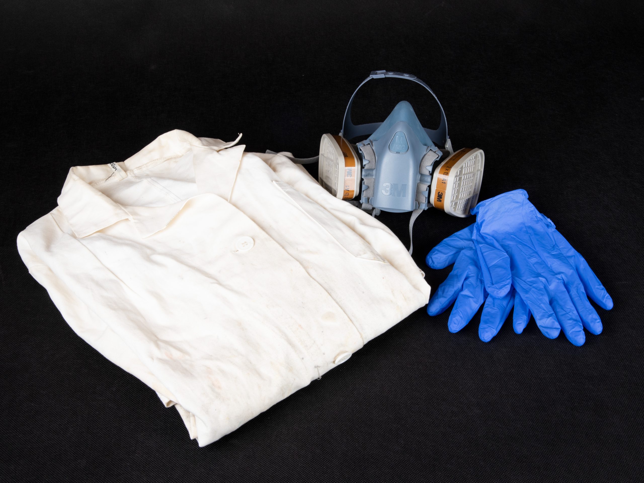
In fact, you’ll be perfectly fine with the equipment you would use while working with things like SLA resins or an airbrush: gloves, protective eyewear and we also recommend a respiratory mask with active chemical filters, sometimes called a half-mask. You can get these in shops with protective gear for painters, etc. Also, don’t rely on respiratory protection completely, and work in a well-ventilated area – a dedicated room, such as a garage or workshop is preferred. The chemicals you’re going to work with are not enriched uranium, of course, but still, the protective gear we just described is a recommended minimum.
Shopping list
Alright, you’ve been warned about toxicity. Let’s get to work then. There’s always a list of things you need to buy for every project so here’s what we got ourselves for the following experiments:
- Lab coat, glasses, gloves, half-mask (see above)
- 3D printer, SLA (resin-based) 3D printers such as the SL1S SPEED work the best because you aim for the smoothest surface possible
- Airbrush – basically, almost any cheap or used will do
- Conductive paint (copper, silver, graphite…) – we recommend copper and we’ll share some more details in a bit
- Degreaser – we recommend galvanic degreaser by Tifoo
- Electrolytes – this is case-specific, we’ll get into details further down in this article
- Electrodes – their selection depends on the electrolytes, we used copper and nickel
- Wires and clamps
- Galvanic brush (or galvanic pen)
- Laboratory electric power supply or a much cheaper variant made with MK3S+ PSU and a step-up converter – see below
- 1000-2000 grit sandpaper, polishing paste, and a piece of cloth
- (optional) Improvised rotating device, either the Rotajig or the one we made with several 3D printed parts and brushed motor (see the description at printables)
- Non-woven fabric
- Vat large enough for your project (clear plastic box, aquarium, etc.).
To be on the safe side, first, use a small amount of the liquid and check whether the plastic material (or filler/primer/paint) is really inert to it.
Electronics
For electroplating, you need a stable power supply. The easiest way is to get a laboratory power supply but we’d like to show you a cheaper solution. All you need is a stronger DC power supply (24V MK3S PSU with its 240 W works perfectly, by the way) and this cheap step-up converter. It will not provide as precise and stable current as a laboratory power supply but for simple home-made electroplating, it’s good enough.
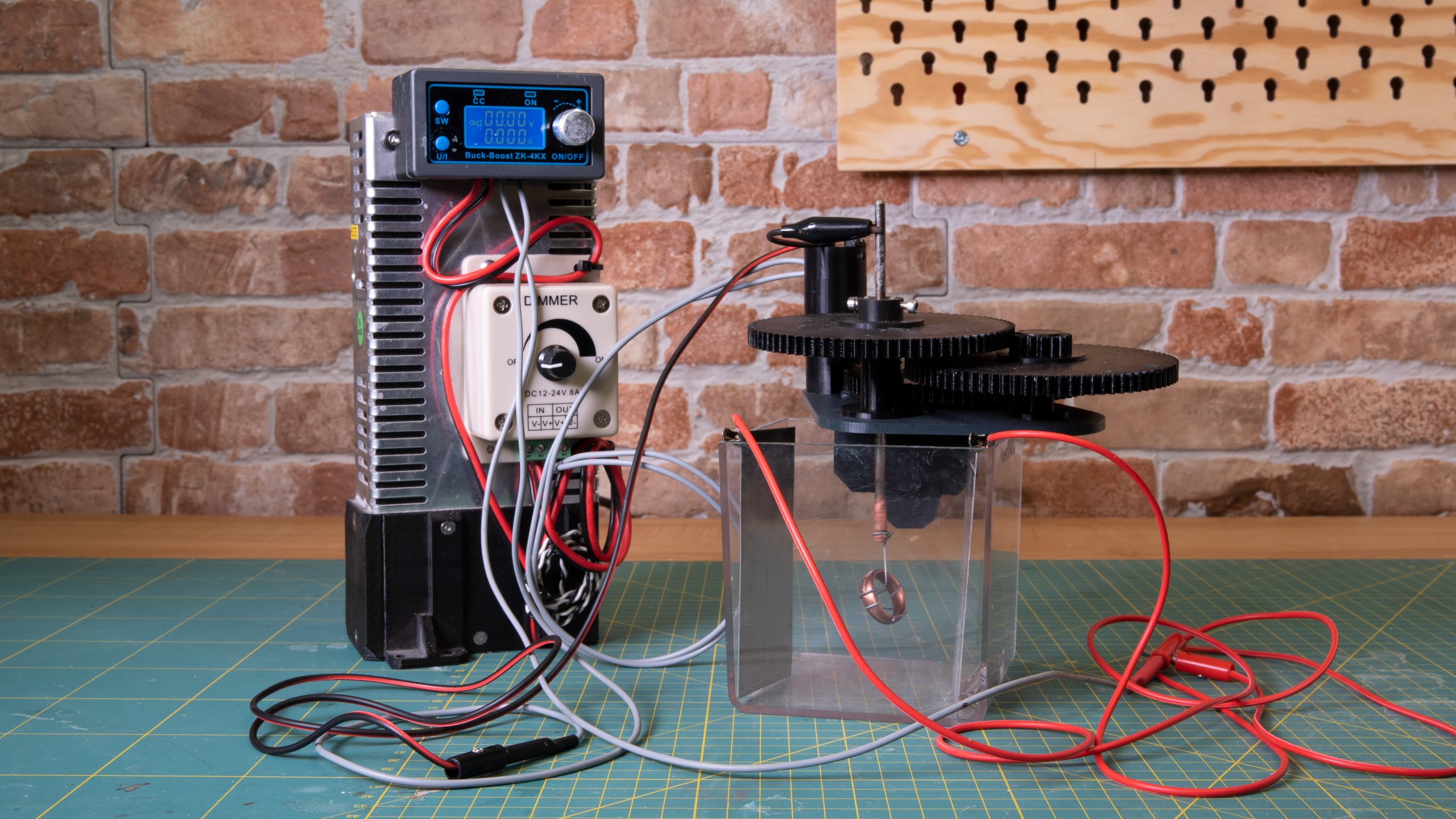
Our electroplating setup
As an optional next step, you might need something to rotate the model inside the bath. Doing this will help the metal to spread as evenly as possible. The best way is to build a Rotajig by Xenoarch but you can also try building something from scrap at home. We simply reused a cheap DC motor, and a speed controller and added some 3D-printed parts. It’s not as good as Rotajig but it works. You can find everything at Printables.com.
Make sure you choose the right wire thickness. Larger models need a higher current, which means you need stronger wires. This calculator might be helpful.
Electrolytes and electrodes
Here’s the setup we bought and tested. We recommend using the same combination but there might be, of course, other methods out there – we didn’t test them all.
The best way to make a desired thick and durable surface finish is to start with copper and use it as a primer of sorts. This metal is probably the cheapest and allows you to make quite thick metal layers. You’ll need a copper solution and copper anodes. Keep in mind that there are various electrolytes for various purposes and these should match with the electrodes and the conductive paint. We chose an acidic glossy copper electrolyte that works well with both copper varnish and electrodes.
Once you have a nice copper surface, you may continue with a thin layer of nickel or chrome – these metals give the model a nice cool shade (as in cool vs. warm colors) that can be either final or work as a barrier between the bottom (copper) and the topmost layer. Nickel and chromium may be applied with a galvanic brush or by soaking in an electrolyte bath. The electrolyte bath works with nickel anodes for both metals and the galvanic brush works well with a graphite anode.
Finally, you can get the most fancy surface finish by applying rare metals, such as gold, silver, or palladium. These elements can be costly, especially if you buy a gold electrolyte. That’s why we recommend you buy a galvanic brush with graphite anode (galvanic pen) and apply it only in thin layers.
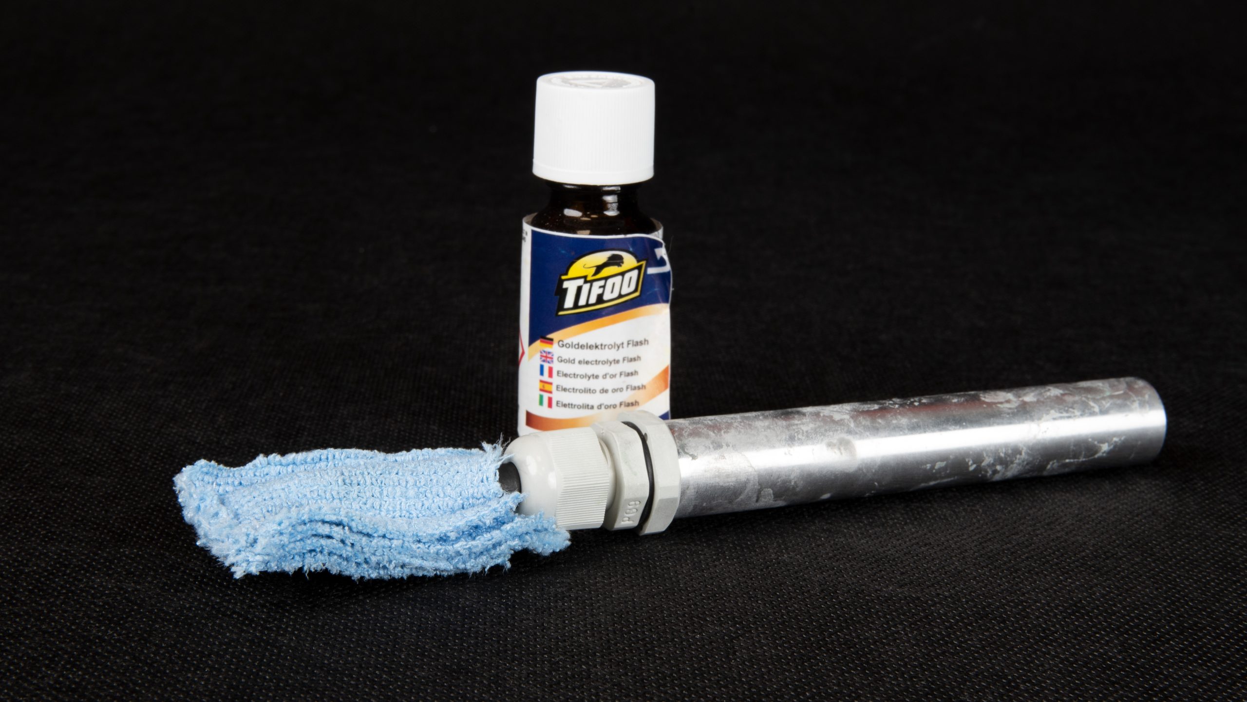
Galvanic brush and gold electrolyte
For some electrolytes, multiple different materials may work as anodes. Electroplating appliance manufacturers (like Tifoo) usually mention recommended anodes and other properties in the product description. Also, when picking the anodes, remember that the bigger the anode surface is, the more smooth and even the electroplated surface will be. However, larger anodes may require higher voltage and current.
You should also know that some metals form a galvanic cell when in contact with other metals. This leads to corrosion and overall bad looks. That’s why it might be necessary to apply a separation layer of metal that does not react with its neighbor. For example, gold must not be applied directly to the copper surface and requires a nickel or chromium separation layer. If you aren’t sure about the combination you’re planning to use, maybe this article about galvanic corrosion might help.
Correct current and voltage
This is, by far, the trickiest part of the whole process. Setting the wrong current and voltage may result in an ugly surface full of imperfections and might eventually ruin your whole project. Most of our tests failed while looking for the correct value but more about it later.
You should be prepared for plenty of testing as the voltage and current differ for various electrolytes and metals. Also, the current can be set according to the area of the model’s surface (you can calculate it in Blender, for example). The current and voltage values are usually given by the electrolyte manufacturer but in our experience, it requires some testing and tweaking anyway.
For the copper base layer, it is recommended to start safe, with values of about 0.2 V, waiting 30-60 min, then raising the values and waiting an hour or so again. Once you reach the optimal value, the surface will start to get nice and shiny. The longer you leave it in the bath, the thicker the layer gets. If you notice some imperfections (bumps or dark spots) on the surface, or bubbles in the bath, the current is too high. Note that our recommended power supply can be set as low as 0.5V. Nevertheless, even a slightly higher starting voltage worked for us.
The nickel and chromium get electroplated in several minutes. You can set the starting values to 2V for Nickel and 6V for Chromium and continually increase the values until you see the bubbles. Once the surface is nice and shiny, it’s done. Or, you can use the galvanic brush.
Final layers with galvanic brush don’t require much testing, simply set the values recommended by the manufacturer.
Polishing
If you think the process wasn’t all that difficult and time-consuming so far, it’s time to get ready for the final phase: sanding and polishing. The 3D printed part should have the surface as smooth as possible. Every detail, every scratch, visible layer, or speck of dust will be visible on the electroplated surface. This is just how the metallic surface works (a real metal or a metallic paint would be similarly unforgiving). Also, the layer we are adding is going to be only several micrometers thick, so it won’t smooth out the underlying foundation on its own, meaning it won’t hide any imperfections. You should sand and polish both the 3D-printed surface and then the copper-plated surface, too. Keep in mind you will need very fine sandpaper (something like 800-2000 grit, gradually increasing) and polishing pastes. For best results, use the wet sanding method. For details about polishing, you might check our older article about transparent parts.
How does it work in the real world?
Alright, let’s leave the theory behind and tell you a beautiful story about metal that fell in love with plastic. This story is based on real events. It’s true, we were the matchmakers and despite all the trouble, we finally succeeded and put those two lovers together in a spectacular way. And everybody was clapping, by the way. Again, we send many thanks to Hen3Drik and his detailed video tutorials that inspired us greatly.
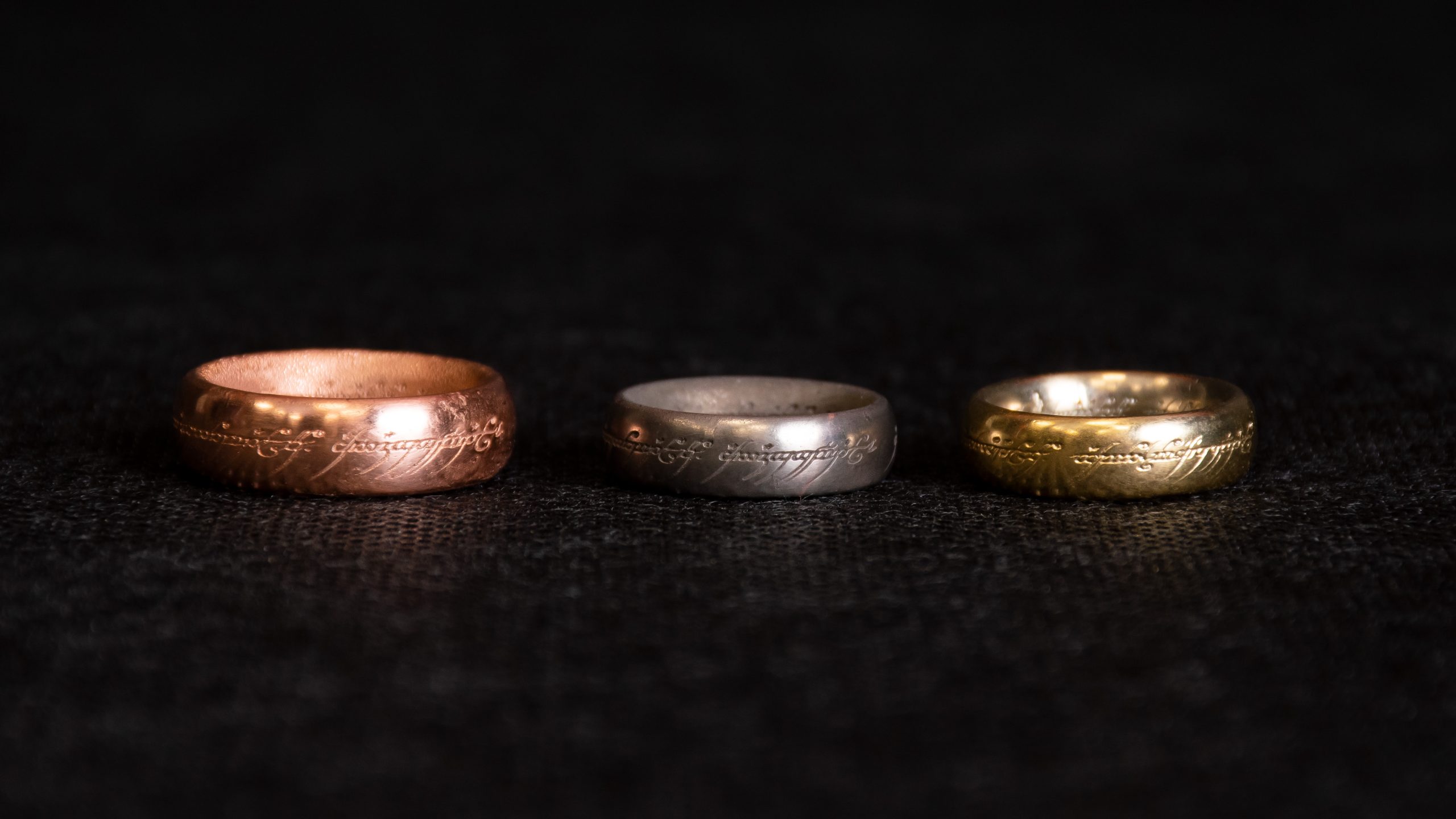
From left to right: SLA print sprayed with copper varnish, freshly copper-plated ring, polished copper-plated ring, nickel-plated ring, final gold-plated ring
Alright, let’s be honest. Most of our attempts did not end as we’d like. Electroplating 3D prints is really challenging and finding the optimal values requires a tremendous amount of time. So here’s what we have(n’t) learned so far:
Electroplating setup
First, we prepared all the electronic and mechanical parts necessary for electroplating in a vat. It’s not rocket science but you may find out that you may need to 3D print some fasteners and fittings as the cables sometimes act as if they were alive. Here are a few quick tips for better results:
- Make “mittens” from a non-woven fabric and put them on the electrodes. They will work as a filter that will catch any particles falling off the anode. Otherwise, the particles floating in the electrolyte might cause some surface imperfections during the next project.
- Clean the oxidized surface of the anodes before using them. You may use steel wool or fine sandpaper.
- Place the anodes as far away from the electroplated model as possible.
- Connect the positive pole of your power supply to the anodes and the negative pole to the electroplated model.
The copper anode is in a “mitten” made from non-woven fabric. The mitten will be hung inside the vat and prevent any particles from contaminating the electrolyte.
Printing and painting
As we already mentioned, it’s best to use SLA models and that’s exactly what we did. FDM (printed from filament) prints may be used too but they would require a lot of postprocessing before they would be usable for electroplating – mainly due to more visible layers compared to SLA. To be honest, we didn’t try FDM, so if you are willing to experiment a little bit (e.g., to see whether a primer would be enough to seal and smooth out the model), let us know – we’re curious about the results! As we already said, for the best effect, the model’s surface must be absolutely smooth. Any bump, scratch, or speck of dust will be visible on the electroplated surface if the electroplating is done properly.
After sanding and polishing with fine sandpaper we had the final model ready for painting. But before that, we degreased the surface (with a galvanic degreaser – see the shopping list). From now on, the model must not be touched with bare hands! Any greasy marks may (and will) remain visible.
Oh, and if you follow our step-by-step tutorial, here’s a quick reminder: don’t forget to protect yourself when painting and working with chemicals!
Clean 3D-printed part (left) and the same part painted with copper conductive varnish (right)
For painting, we used an airbrush to make the surface as smooth as possible. We bought three types of paint to test which one works the best. Most of the people trying the electroplating method found that the copper conductive paint worked the best in most cases but we wanted to put under test some other types of paint too. That’s why we bought conductive copper paint, graphite paint, and silver paint.
Copper-sprayed parts ready for electroplating
Copper conductive paint – we’ve mixed the copper conductive paint with acetone 1:2 and this worked very well. With a low acetone ratio the paint might dry on the needle tip or mid-air, right as it blows out of the nozzle – simply fix it by cleaning the airbrush and diluting the paint a little more. Also, undiluted paint sprayed with an airbrush may result in a rough surface or may not even adhere to the surface. These issues troubled us a lot during our attempts.
Graphite conductive paint – The paint we bought was water-based and diluted just enough for applying with a regular brush. We didn’t find it suitable for the airbrush, though, as the particles were too large and clogged the nozzle frequently. However, the regular brush worked fine and the paint was conductive pretty well. It even got a somewhat glossier finish than the copper paint, as it reacted differently on varying voltage. But, every bump, bubble, and line caused by the brush was visible on the electroplated model. Also, for some reason, a few spots remained dark, without copper plating, even with the color thoroughly mixed and well-spread.
Silver conductive paint – Again, this paint was water-based and suitable only for applying with a regular brush. The airbrush clogged with every attempt. The conductivity of silver is well enough for electroplating. However, after some time, the copper started to corrode on the paint, so we don’t recommend this combination.
Copper, silver, and graphite paint
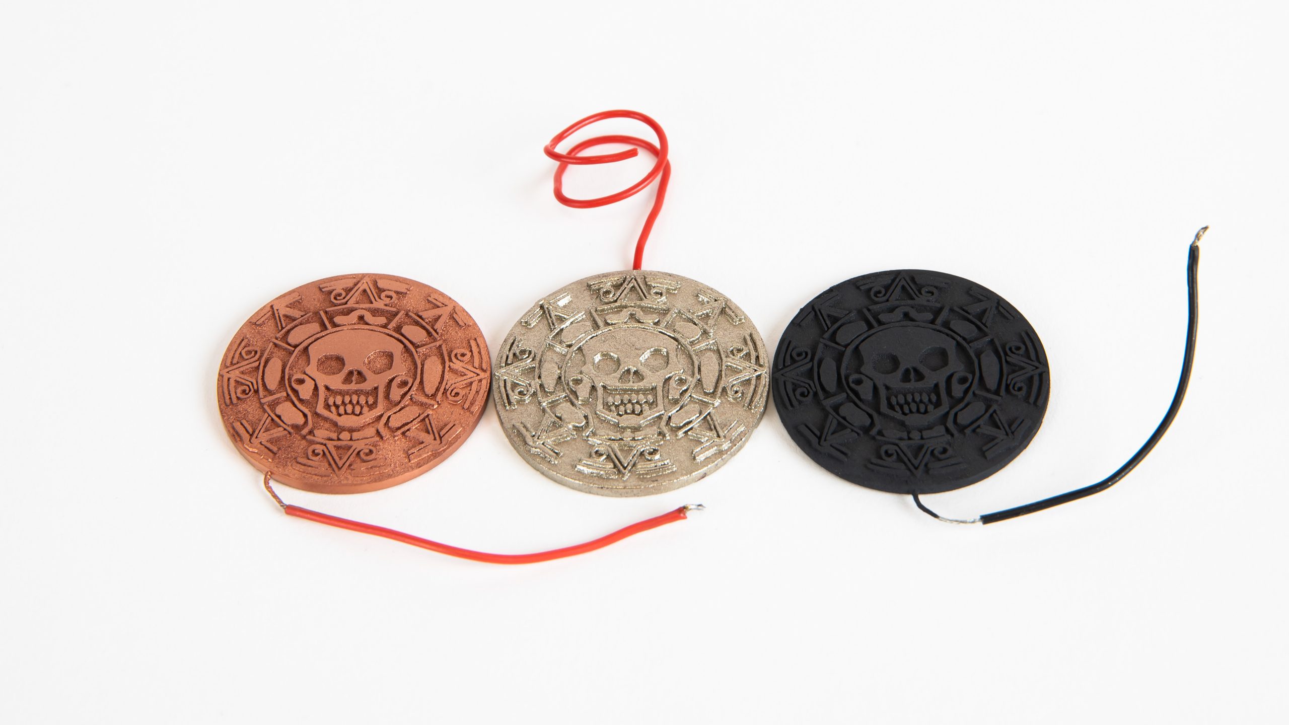
The conductive paint after copper plating. From left to right: copper paint, graphite paint, silver paint.
You might be thinking: how about avoiding the need to paint the model by simply using conductive filaments or metal-filled PLA? Unfortunately, basic metal-filled filaments are not conductive at all (their metal particles are not connected) and conductive filaments are extremely brittle and with dubious conductivity. Plus, the FDM print’s surface is far from being smooth, so with all that postprocessing you wouldn’t save much time anyway.
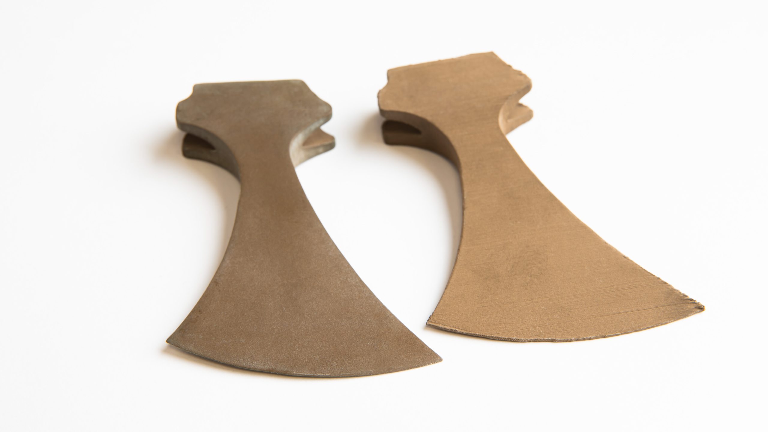
Copper-filled filament is not conductive enough for electroplating, neither in its unprocessed form (right) nor when polished (left).
Soaking in copper electrolyte and polishing
Once the model was painted, we wrapped it with wire. The model in a wire cage now works as a cathode. The wire should touch the model at several places to ensure that current flows through the model all the time. Don’t worry that the wire would block the metal – it is necessary to move the model around during the process, so the wire won’t stay in one place.

Painted ring in a wire cage.
Finally, here comes the electroplating itself. As we recommended previously, we started with the copper electrolyte and copper anodes. This gave us a relatively cheap and quite thick base layer of copper on the model. Well, at least we thought it would…
At first, we tried electroplating a few small models and we got mixed results. One of them went pretty nicely, so we did some sanding and polishing and eventually, we got quite a nice result. Not perfect but we considered it very good for our first try.
But then, things went south on us. We repeated the process with the same settings and didn’t get the desired result. We tried to electroplate multiple models with various settings and they ended with a rough and matt surface every single time. Now, honestly, failing to make the first metallic layer is really a test of patience. Every part we tried to electroplate, took us a considerable amount of time printing, sanding, painting, and electroplating. Every single piece took at least 5 hours to electroplate.
Some typical flaws we made during electroplating: the copper varnish layer was too thin and poorly diluted, resulting in peeling off during the copper plating (the white spots). The overall appearance is matte and rough due to the wrong combination of current, anode size, and poorly made varnish layer. Dark spots are the result of corrosion, which resulted from poor washing after the electroplating process.
Luckily, not all was lost. Even though the surface was far from perfect, the copper layer was there. All we needed to do was to improve the surface finish. With some sanding and polishing, we got pretty nice results. However, keep in mind that the layer is rather thin, and sanding it too hard may cause cracks and destroy the layer completely, so be careful.
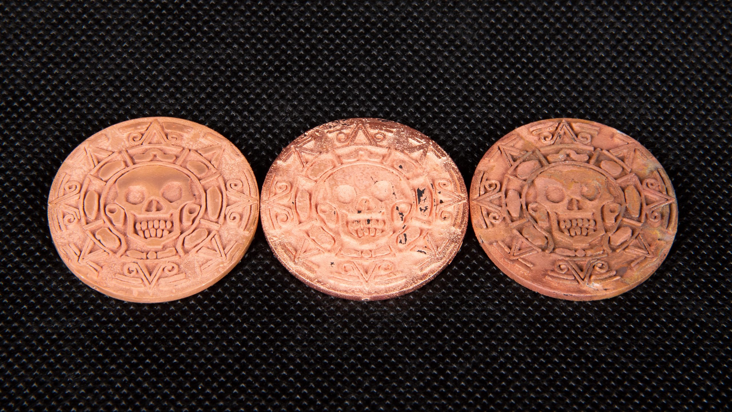
Copper-plated parts before polishing.
Copper-plated parts after some polishing.
Now, if you decide to try the process yourselves, here’s the voltage that worked for us (once). However, as we said, the voltage and current may be different for various models, anode, and bath sizes, various types of electrolytes, etc. You really need to do some testing yourselves.
- Set 0.5V for 1 hour
- Increase to 0.7V and keep 1 hour
- Increase to 1-1.2V and keep 4 hours
- Rinse in distilled water when done
Move the model in the copper wire cage from time to time to avoid a situation where the wire would become welded to the object.
Slowly rotate the model in the bath (move it from time to time if you don’t have a rotating device)
We even tried to set the values according to the model’s surface. The glossy copper electrolyte should work at 1-7A/dm2. So, we printed a cube that had the surface as close to 1 dm2 as possible and set the values accordingly (1A and slowly increasing up to 4A, which is the maximum for our power supply). Again, we got the rough matt surface finish. Only around the edges, it got a somewhat shinier finish but it was still not what we wanted. So, we recommend adjusting the voltage instead.
Finally, we gave it a proper look and figured out that we may have failed to paint the surface properly in the first place. Since the same problem occurred for the batch made with the same color mixture, no matter the voltage and current, we suppose the color was probably not diluted enough and caused some surface imperfections that we underestimated. Plus, we didn’t calculate the copper electrode surface and probably used oversized electrodes for our tests. This surely didn’t help either.
Degreasing
Finally, the most problematic step is behind us! We sanded the model and were happy that it wasn’t all lost. We degreased it again with the Galvano degreaser (soaking for a few minutes) and continued electroplating.
Soaking in other electrolytes and polishing
The polished smooth copper surface looked nice already, but we wanted to have a nice shiny silverish/chromium surface. To do it, we applied more layers. The process is pretty much the same as with copper electroplating, but much faster. You need only a thin metal layer for visual purposes (or as a thin barrier for gold plating). Here’s how we did the nickel plating for every single part:
- Set 2V and watch the model’s surface. If the bubbles appear and the model gets nice and shiny, keep the voltage as it is.
- If you see no bubbles, slowly increase the voltage.
- If the surface gets black and matt, with too many bubbles around, the voltage is too high.
- Move the model from time to time to prevent anode shadows and welding.
- Stop after 5-10 minutes.
- Rinse in distilled water when done
Now, the model has become silverish, but slightly more matt. However, since we applied only a thin layer of nickel, we didn’t have to do any thorough sanding, only a quick polishing.
Properly sanded and polished copper-electroplated ring, nickel-plated ring, and final gold-plated ring
Electroplating final details with a galvanic brush
Finally, we electroplated the final layer with the galvanic brush and gold electrolyte. This helped us to save a lot of material (and money). The galvanic brush works with higher currents and it is harder to set improperly. Our settings were the following:
- The anode (wire with clamp for example) touches the model’s surface
- Galvanic brush works as cathode, with the sleeve soaked with gold electrolyte
- Voltage: 7 V (for gold electrolyte)
- Rinse in distilled water when done
A galvanic pen with a sharp point (or some sort of a tiny wick) might work better for small objects and surfaces, such as jewelry.
Waste disposal and electrolyte lifespan
One final step. Again, we’re working with toxic chemicals. This means not only that this step may pose a health risk but that it’s also toxic to the environment. Do not dispose of the chemicals into the general waste (not even the paper towels), do not pour it in the sink. Always handle the waste as toxic, put it in a sealed container, and dispose of it as any other dangerous chemical.
Also, you might want to know how long it takes until the electrolytes get depleted. To be honest, we don’t know. At least we didn’t deplete them during our tests. The manufacturer states that electrolyte depletion can be recognized by slower metal deposition. Also, when using a copper electrolyte with copper anodes (or any other metal electrodes with matching electrolyte), the electrolyte’s lifespan should be very long, as the metal from anodes dissolves slowly into the electrolyte. However, it still gets contaminated and the brighteners used up.
The final result
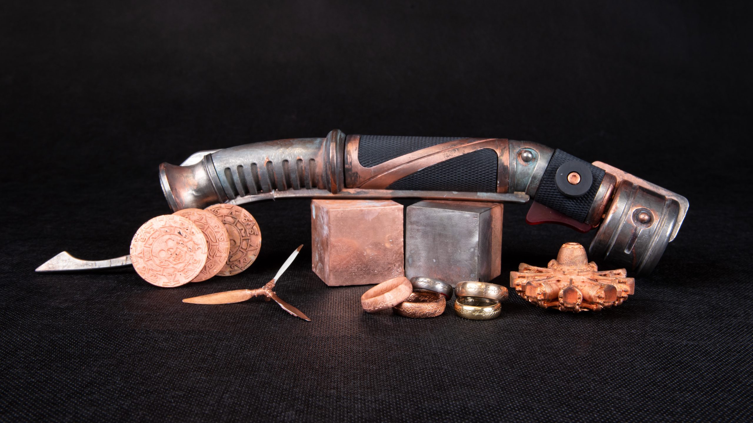
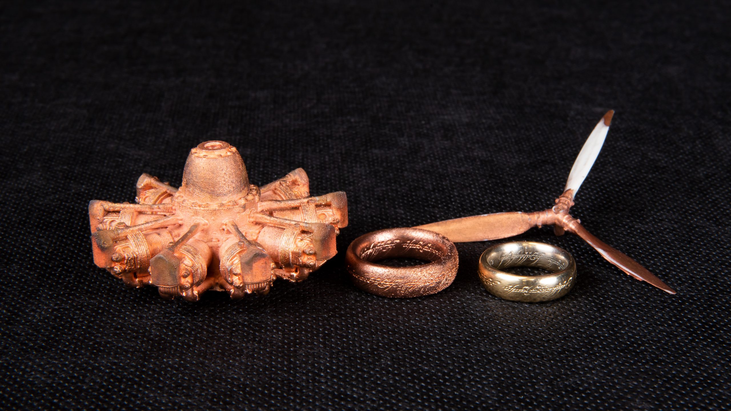
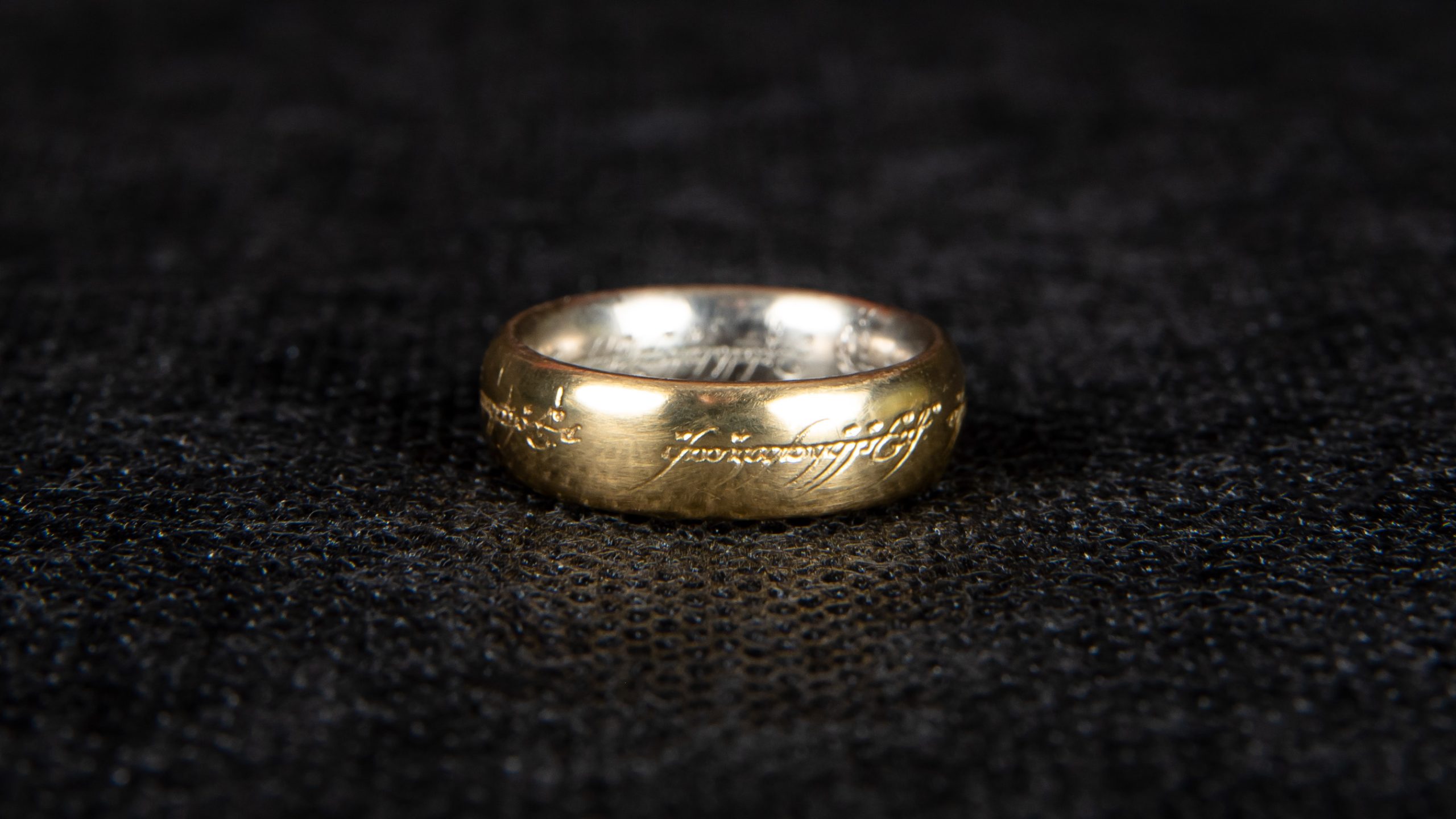
We did it! It’s over, it’s done… Just have a look at how amazing it looks. Would you believe this ring is a plastic SLA print and not an extremely precious artifact from Mount Doom?
Also, we made this cool Count Dooku’s lightsaber. With numerous mistakes on the way, we didn’t get the perfect and glossy surface we wanted, but instead, we got this vintage weathered look, which actually looks amazing, too.
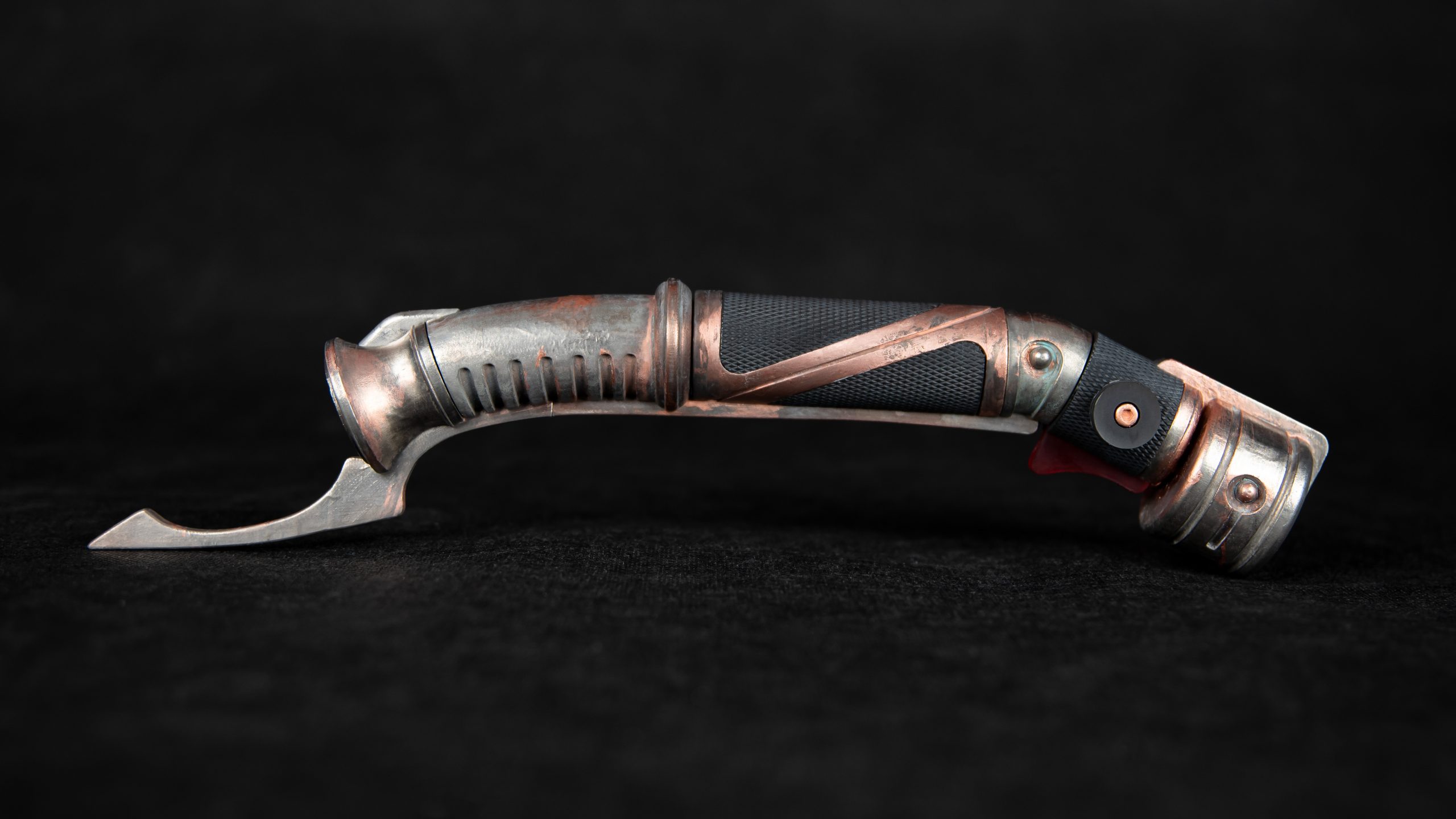
Used models: The One Ring by Papp, Count Dooku’s Lightsaber by UnimatrixRed, Hamilton Standard aircraft propeller and Piaggio Stella P.IX by Vladimír Kafka, and Pirates Of The Caribbean Aztec Gold Coin by Tobse
Happy printing!
I tried electroplating a few years back using a test cube and graphite paint for a copper layer.
I let that stuff in the fluid for about 24h and I got a real ugly but very heavy cube (must have got a thick layer of copper).
I never had time to work on that topic again, but since then I wonder whether prints (FDM) would become mechanically more robust when applying a really thick layer (thin layer is useless of course, since actually only the paint got plated and not the actual cube and therefore the sturdiness is just as good as the adhesion of the paint). If that layer gets over – let's say – a whole Millimeter or more, would that be as strong as a comparably thick plate of normal copper?
Additionally since you use acetone for the airbrush copper paint: Anyone thinking about ABS as well? because if the acetone slightly dissolves the surface of the ABS print, then the copper particles should bond much better with the object and therefore should increase the adhesion -> sturdier metal coating -> really strong printed parts?
cheers
Using acetone-diluted color on the ABS print sounds interesting. But I'm afraid that it wouldn't give much better results. I found that the copper paint layer didn't actually become part of the electroplated metal surface but instead, it remained as something close to a separation layer. You can see it slightly in the video where I peel the cube's surface. But again, I made numerous mistakes on the way and maybe it might work. I'd be happy to see if anyone tests it.
Have you tried using filaments with infused metals?
Rather than using the paint as a bonding agent, wouldn't it be possible to just have the copper filament attract copper from the fluid?
If so then you would have a layer that is molecularly bonded to the copper, right?
well, I must have skipped that part. I see that you have played with that idea.
That is too bad to hear, I wonder if the PLA could be treated with some kind of electrolytes to carry the charge from one particle to another?
I was literally just looking at ProtoPasta new composite filaments 10 mins ago, gotta give this a try ;o)
Hi there,
I am a teacher for electroplating at a professional school in Germany. Some hints that could improve your results based on your pictures:
1. Rotating your parts is not necessary, more important for most electrolytes is to move the electrolyte. That can be achieved by some magnetic stirrer or by bubbling air through the bath by using simple and cheap pumps for fish tanks. The metal ions are simply not fast enough to get from your anode to your printed part in time at high current density and your copper layer than will get matte and "powdery".
Maybe the most important steps during electroplating are washing. Every contamination in your electrolyte can cause trouble, so be sure to wash all the parts after every step, especially after degreasing. Usually the degreasers have a higher pH while your copper electrolyte is at a very low pH. At these small volumes, even small amounts of degreaser being transported to your electrolyte can mess things up, so give your parts a good wash in clean water and maybe a quick dip in diluted sulfuric acid before you got to the copper plating. The acid wil remove any residual amounts of degreaser and since almost all glossy copper electrolytes are based on sulfuric acid, you are not introducing additional contaminations to you copper bath.
Optimize your part orientation. The current density you set up at your power supply is only the average current density. The local current density at your part can be quite heterogenous. The distance between anode and kathode is one major factor for this so try to orient your part as parallel to the anodes as possible and don´t rotate it during plating. Increasing the distance between anode and kathode will also work, but this means of course you will need a larger bin for your electrolyte and of course a bigger volume of electrolyte.
Keep your parts wet. A dry surface is prone to oxidation and an oxidized surface cannot be plated since most oxides have almost zero conductivity. So if you have to store your parts between degreasing and plating or between different plating steps, always store them in water or in diluted acid (sulfuric acid since it is quite cheap)
Finally, gold on copper is possible, but you are right that in most cases a nickel layer is put between copper and gold. However, the main reason is not corrosion. Gold and copper can easily mix (guess where rose gold comes from) and so the color and properties of your gold layer will change over time caused by mixing of the two elements (sounds funny since both metals are solid at room temperatur but this diffusion still happens). Nickel will not mix with gold and so your gold layer will be safe.
If you speak german, have a look at my school if you like:
https://tbk-solingen.de/bildungsgaenge/oberflaechenbeschichter/
thanks for the very clear addition to this piece.
Thank you! This explains a lot.