


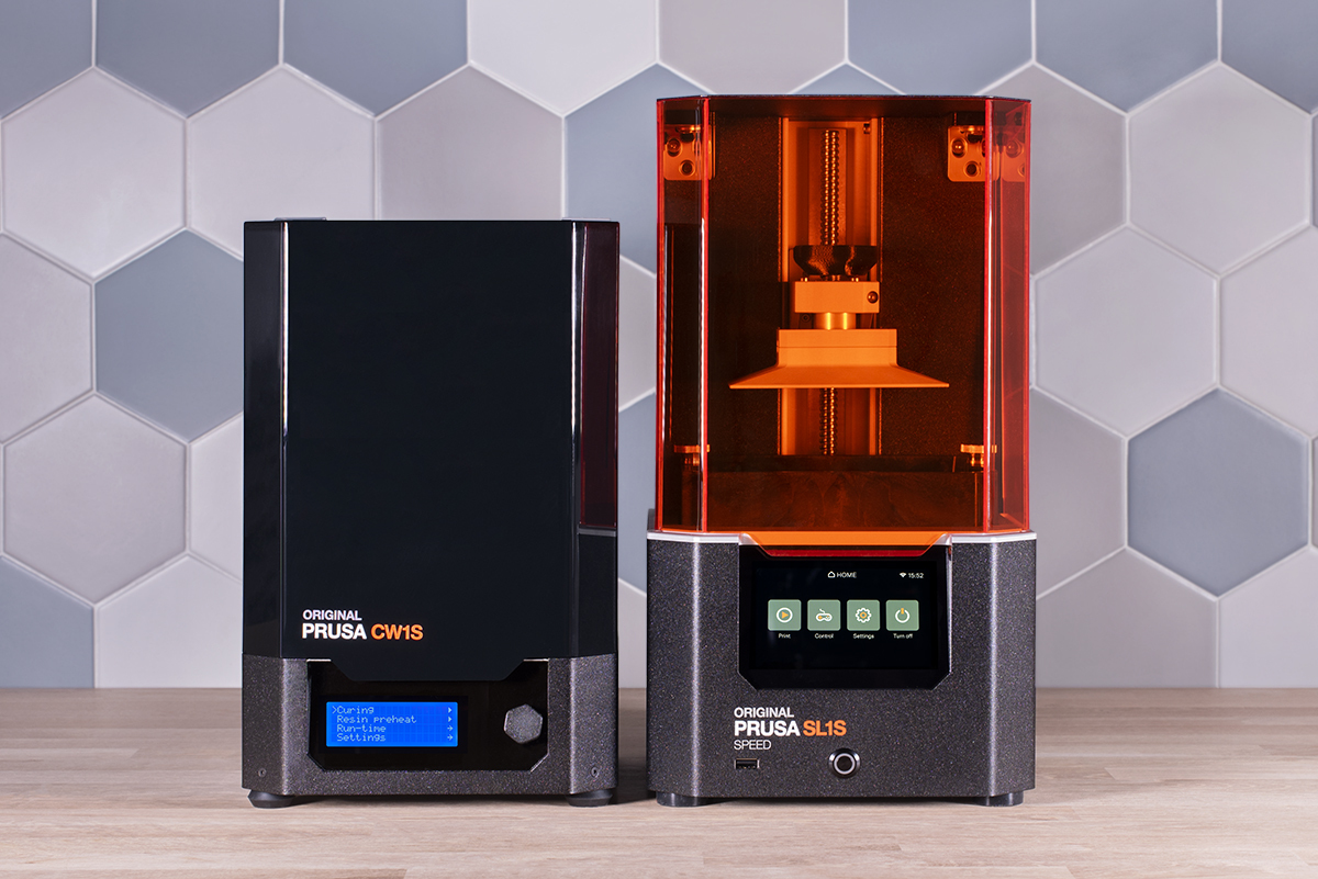
In today’s dev diary, we’ll explore the world of pixels and subpixels. In addition, we’ll shed some light on how we managed to tame UV light, and most importantly, how we managed to make the Original Prusa SL1S the fastest desktop MSLA 3D printer.
We launched the Original Prusa SL1 in May 2019 – a robust masked SLA 3D printer with a heavy aluminum frame, high-quality components, RGB exposure display, and a 64-bit motherboard. The exposure times were around 6-7 seconds, the movement of the platform and tilt mechanism took about five to seven seconds. Over the two years, we focused on making the SL1 better and better, mainly through firmware releases and accessories such as the display calibration adaptor. And we wanted to make it faster. A lot faster. A monochrome LCD was the way to go.
The curious case of pixels and subpixels
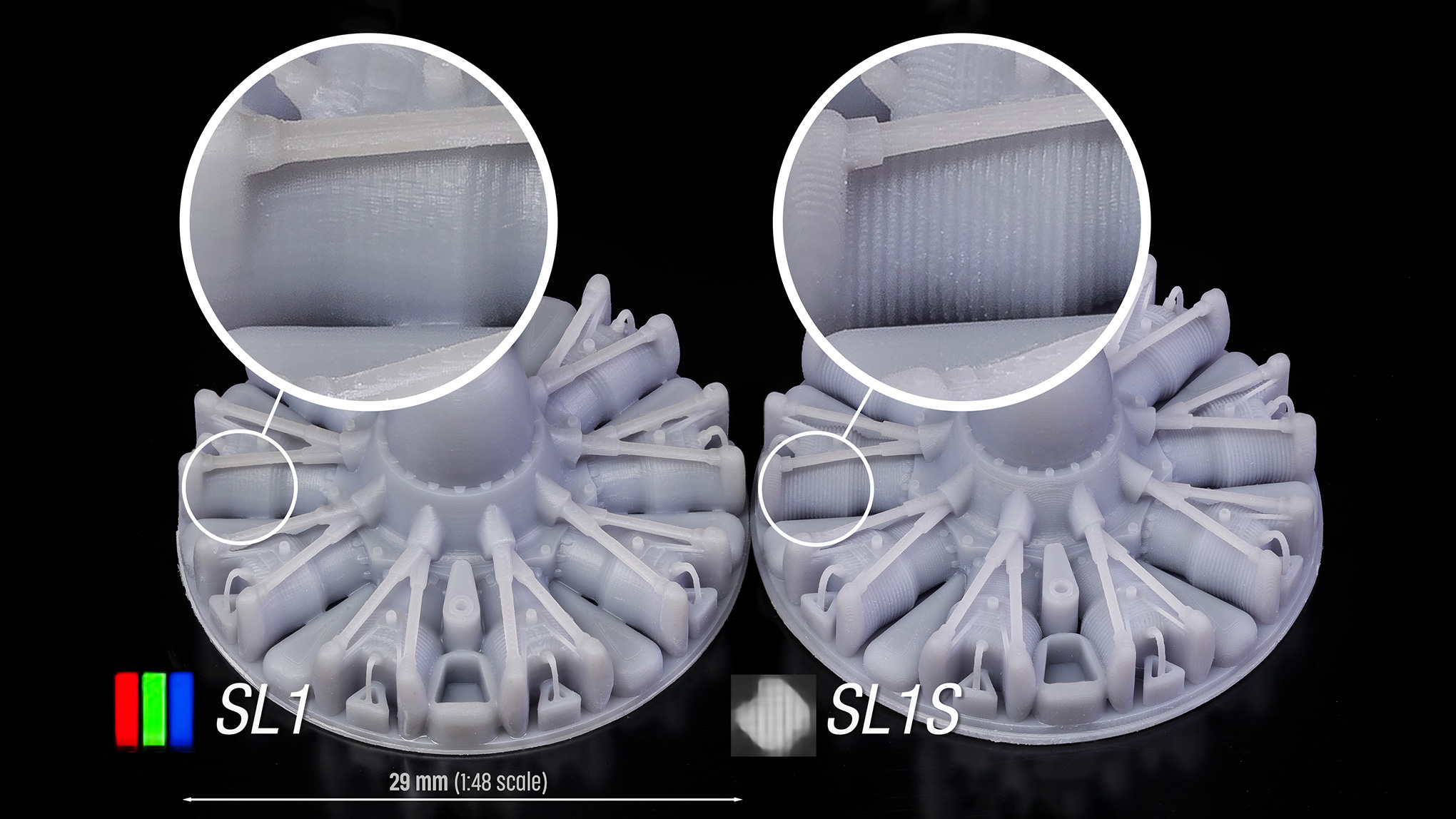
However, we quickly learned that simply swapping the RGB display with a monochrome counterpart was only the beginning of a more complex case. The printer worked, sure. However, all models suddenly lacked details and appeared blurry compared to the prints from the stock SL1. So we started investigating the cause of this effect. The new screen has pretty much the same resolution – so why the sudden change in quality?
We quickly figured out that everything boils down to how light rays are cast through the display. It’s a rather complicated matter, so the best thing is to demonstrate the effects using an illustration.
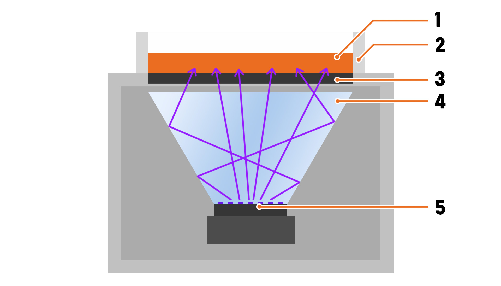
1 – Resin | 2 – Tank | 3 – Exposure display | 4 – V-shaped reflector | 5 – UV LED panel
This illustration shows the original light reflector from the SL1. It consists of a UV LED panel at the bottom and a reflective rectangular funnel. The LEDs cast UV light rays, which bounce off the reflective surface under various angles. These rays then pass through the mask displayed on the LCD: dark areas (pixels turned off) block the UV light, bright areas (pixels turned on) allow UV light to pass through. This is the general principle of how a masked SLA 3D printer works. That’s nothing unusual. To see where it gets really interesting, we have to look closely. Very closely.

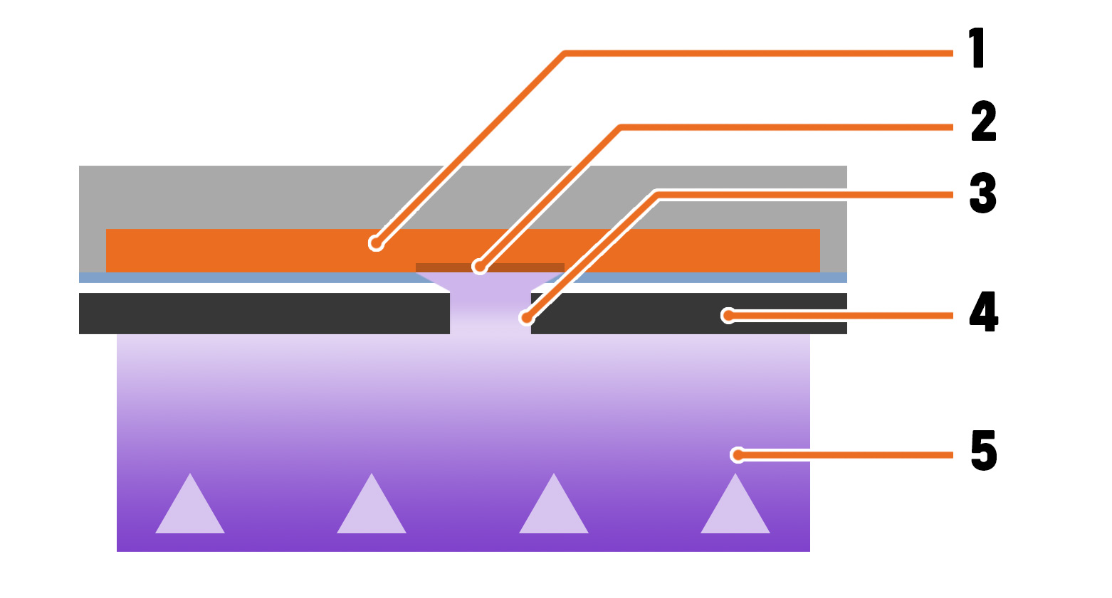
1 – Resin | 2 – Solidified resin | 3 – UV light passing through a subpixel | 4 – Exposure display | 5 – UV light
There’s a simple reason why an RGB display is called RGB: every pixel consists of three subpixels – Red, Green and Blue. Only the blue subpixel can transmit a substantial amount of UV light, which is still a mere one percent! It’s enough to cure the resin, though. Red transmits a completely negligible amount, while green blocks the UV light nearly perfectly. For simplicity, imagine that the blue subpixel is a narrow gap. The UV light bounces around the reflector thanks to the reflective walls, which means it passes through the gap under various angles – this is why the actual area exposed to UV light is slightly larger than the blue pixel itself.
The monochrome LCD doesn’t have three subpixels per pixel – it’s just one large pixel that you can turn on or off. Which causes this:
1 – Resin | 2 – Solidified resin | 3 – UV light passing through one pixel | 4 – Monochrome exposure display | 5 – UV light
The light, which passes through the larger pixel, exposes an area even larger than the pixel itself. One pixel on the monochrome display is larger than a subpixel in an RGB display. This is why our first combination of a monochrome LCD and reflector caused a loss of details! And there’s another thing: in the areas where light from two pixels overlaps, the model becomes distorted due to overexposure. Not an easy issue to solve. Yet, the benefits of using a monochrome display easily outweigh the negative aspects – we simply had to figure out how to cast light through it.
Taming the light rays
Our goal wasn’t only to decrease the time required for curing one layer. We wanted to increase the print quality even further while taking advantage of our custom-made tilt mechanism for faster and more reliable printing. This was one of the reasons why we didn’t want to use an off-the-shelf solution.
We already had the new monochrome display inserted into the SL1 frame. It was a rather easy job because the SL1 was built with upgradeability in mind like all of our machines. Then, we needed to find a light source that would produce a collimated beam of light – this means that the light rays don’t spread into sides; they remain parallel. The other important aspect is the homogeneity of the light source. If there is a difference in the strength of the light across the print area, some parts of the print may be over- or underexposed, an unwanted effect in both cases.

We contacted over a dozen tech companies and went through a long list of various lights sources over a year. We tested line lasers, LED scanner assembly, separated reflectors, TIR lenses, custom-made LED light pipes, and, of course, custom-made lens assembly combined with a large LED array. None of these managed to tick all the required boxes – only the custom-made lenses came close. Our first attempt was based on the Fresnel equations.
We turned a plano-convex lens into a Fresnel lens, which was made either by casting a UV-resistant optical resin into an SLA print or by pressing an inversion matrix into molten Plexiglass. However, achieving the required level of quality proved to be nearly impossible. Finally, we ended up with a lens array which gave us a required level of quality in terms of light collimation and homogeneity. However, it wasn’t a typical “eureka moment,” we still had a ton of work ahead of us.
Let’s make it faster!
It’s hard to tell what gave us the idea of making the SL1S not just as fast as possible but, simply, the fastest. I believe it was about four months before the launch. We had everything laid out on the table: a monochrome LCD with a roughly 5% efficiency/light transmission (compared to the 1 % of the RGB screen), brand new lenses, and a new LED array was in the works. We were reaching considerable increases in speed (also thanks to improved tilt mechanism speed), even the print quality went up. I guess it was one of the “what if…” moments. What if we massively increased the power of the UV LEDs? Two times? Four times?
“How much faster do you want it?”
“Yes.”
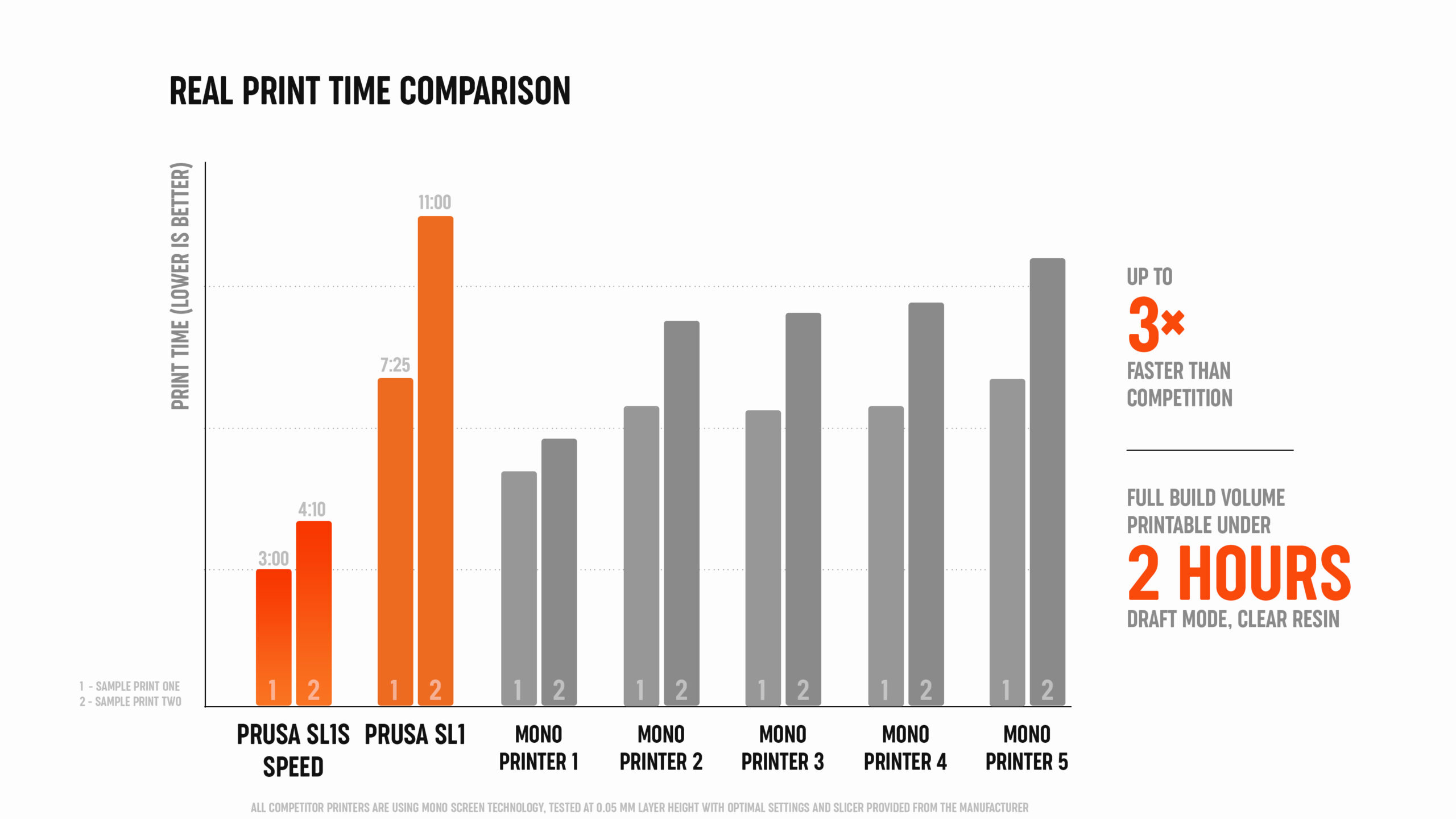
Before I tell you the rest of the story, let me take a slight detour here – let’s talk about the tilt mechanism and print times. When you browse through various SLA 3D printers, the commonly published information is the exposure time per single layer, which can be anything from two to eight seconds. However, this is just a part of the real experience. The printer also has to move the platform upwards after a layer is cured to allow the resin to flow back under the platform and spread evenly. Then, the platform is lowered back into the resin tank and the print continues. This process takes some time – several seconds at a minimum. So the total print time is not just exposure per single layer multiplied by a number of layers, but rather exposure per one layer plus the entire up&down motion multiplied by the number of layers. In a vast majority of cases, our tilt mechanism is considerably faster. So don’t judge a 3D printer merely by comparing the exposure times.
Back to the UV LED array! First of all, the new UV LEDs we use are the cream of the crop. The manufacturer we chose tests every single LED manufactured, then separates them into so-called “bins” based on how good the parameters of the LED are, so we went straight for the top. 🙂 The new LEDs are still twice as expensive as the LEDs in the original SL1 and the quality really shows. And again, getting it all work was more complicated than it may sound – new LEDs required larger current (1,4 A vs. 0,7 A), something that the built-in power supply unit in the SL1 could not deliver. This is why we decided to use the PSU from the Original Prusa MINI and hook it up through a custom-made Booster Board, which provides power to both the motherboard and the UV LED array. Voilà – 1.4-second exposure and 3-second tilt times were within reach.
With the new monochrome LCD and much better LEDs, we could also discontinue the calibrator for the LCD screen. The transmission rate of each display is now measured using a special testing station and the data are written directly into the LCD module’s electronics, which wasn’t possible before. Once the module is installed in the printer, the information about its transmission is read by the system, which adjusts the necessary values accordingly. Thanks to this process, all of our SL1S printers are virtually identical in terms of performance.
Make it work!
The final stage of this little puzzle was to make it all work. It was a lengthy process that involved rigorous testing and constant adjustments to the optical array. For several weeks, we waged a tough battle against parasitic rays – suddenly, all our prints started to become stuck at the bottom of the tank. They simply detached from the print platform. What now?
We figured it out eventually. The old lens assembly allowed for UV light rays to cross in certain areas of the display, creating overexposed spots. In these places, the resin solidified quicker compared to the rest of the print area, which caused the object to become stuck to the FEP film (the bottom of the tank). To solve this problem, we had to adjust the lens, the light separation grid under the lenses, and the LED panel in tiny increments until we found the correct position. Oh, and since the cooling of the SL1 was developed for the RGB display and its V-shaped reflector, it didn’t work with the new solution at all – back to the drawing board!
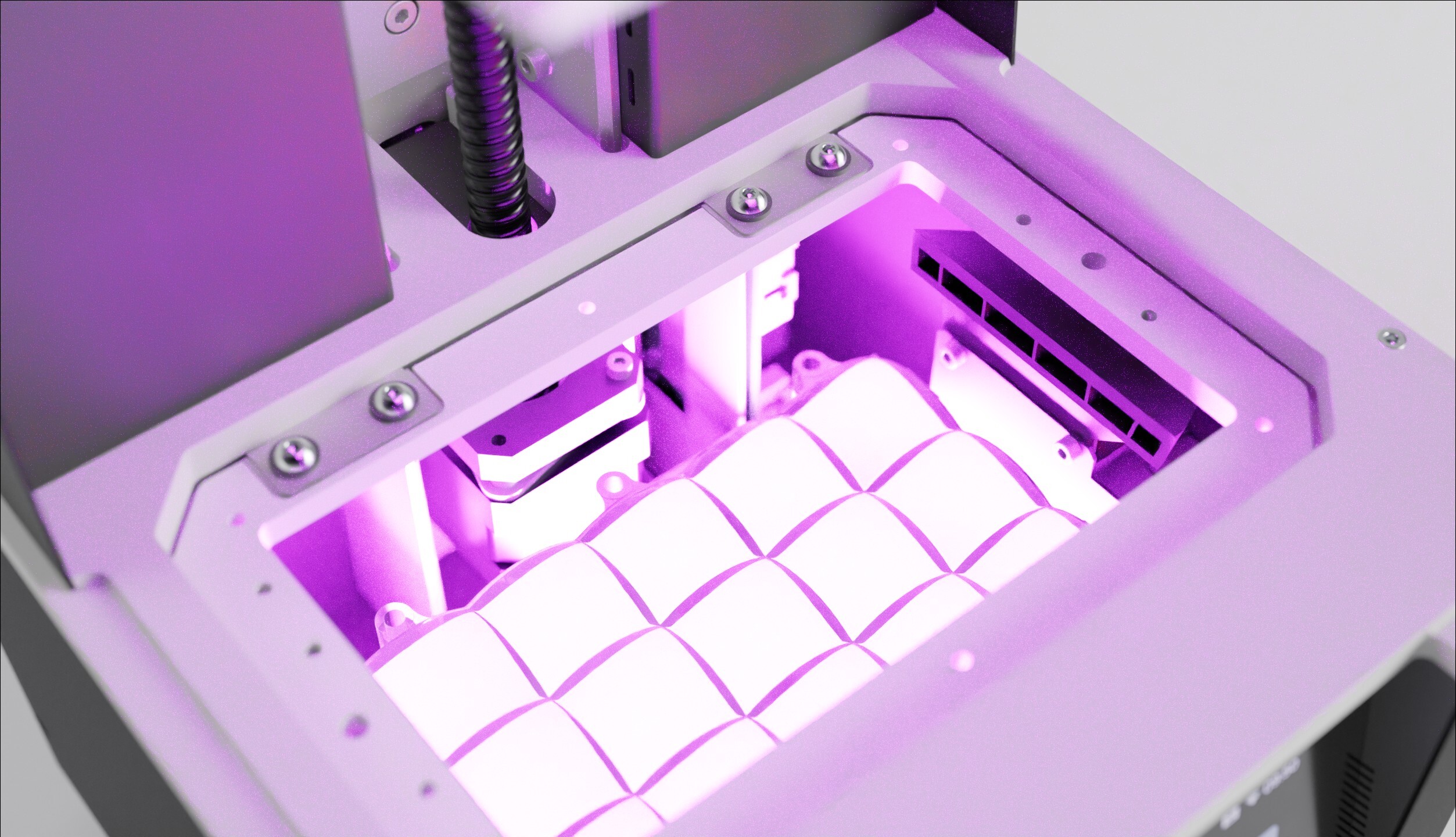
The trouble was that the airflow, which we designed specifically for the V-shaped reflector and less cluttered insides of the machine, was suddenly completely useless and the printer began to overheat. The new LED panel with the reworked optical assembly is much larger compared to the old solution and due to the bulkiness of the entire block, air couldn’t reach the critical components.
Definitely not as easy as simply swapping an RGB display for a monochrome LCD.
However, in the end, we made it all work – and it works beautifully! The SL1S may look the same from the outside, but the internal parts are almost completely replaced with brand new components. Not only can the SL1S print fast, but the quality of the produced models is also exceptional. We pushed the exposure times all the way from 7-8 seconds to a mere 1.4 seconds and made the tilt mechanism nearly three times faster. It was a long journey. We often felt like we’re on the brink of a new discovery just to hit a dead end a few days later. It’s all part of the process. So, finally, after many months of work, the SL1S is here (we’ve been shipping it since early July) and I’m really happy with how it turned out.
Great work as always! Just wish it was a bit more affordable.
Any plans for a mini/lite version?
Possibly, we are keeping all options open for the next generation of our SLA printers. 🙂
Hi! I’ll be looking forward to visit this page again and for your other posts as well. Keep it up! Thank you so much for sharing us some information about this one. You have such a very informative and interesting page! We are livecoupons.net! Best place for coupons.
This was quite interesting to read. Yes, the SL1 wasn’t cheap and in the beginning I asked myself sometimes if it was the right decision. But after 1,5 years of printing with great results and now with the upgrade-kit to the SL1S SPEED (which hopefully will be shipped the next days 😉 ), I think I definitely went for the right MSLA printer. Looking forward to my “new” printer. Good job, Prusa-Team!
When can we expect profiles to take advantage of this speed to show up in PrusaSlicer?
It is such a pity that the cost of the upgrade is as much, or more than, a much higher resolution mono printer from another manufacturer. Yes it is certainly better built quality than the cheaper printers. I love PrusaSlicer, but it has not received new features since I started using it. Variable slice thickness is something that I expected to be in the SLA part of PS long ago, as this is now an old feature of the FDM side. So I have to use a third party slicer to slice files for my Prusa SL1. Do I feel like investing more money into a printer that I feel is not supported well in PS software? I just don’t know.
Fascinating to read some of the development efforts that went into producing the SL1S – thanks for the effort.
What a shame that the update would cost as much as or more than a monochrome printer with a considerably greater resolution from another brand. Yes, it has a higher level of construction than the less expensive printers. PrusaSlicer is great to https://drivemad.io, however since I started using it, no new features have been added.