


If you’re modeling something in Fusion360, you’re probably used to defining dimensions by directly inputting values in sketches or when using tools like extrude, or chamfer. This works fine when you’re designing something from scratch and the part doesn’t really have to fit with any existing objects.
But that’s very often not the case, right? Mechanical parts usually need to fit perfectly with other parts. And sometimes you might even want the part to fit various different sizes or types of objects. Say, a wall-mounted holder for an aluminum LED profile. You don’t want to re-draw it from scratch every time you buy a slightly different one.
Or a self-watering insert for a flower pot. Ideally, you’d like to be able to quickly resize it to whatever size your pot is. This is where parametric modeling excels. In short, if you go to Modify – Change parameters, you can define dimensions and name them. If you have experience with any kind of programming, these are basically variables.
You can then use these variables whenever you’re defining dimensions. And you can even do basic math with them. For example, you can define that an edge should be “thickness*2” long.
If you then, later on, want to resize your model, instead of painfully changing the dimensions everywhere manually, you can simply open the parameters window, change the values here and see the model updating in real-time. It’s really cool and if you’re not using this feature, you’re missing out a lot!
Let’s take a look at two examples and actually try to modify them to fit a different sized object.
Example 1 – Self-watering flower pot insert
First, we’ve modeled this without the use of parameters, just like you’re probably used to modeling. So how can we change the size in this case?
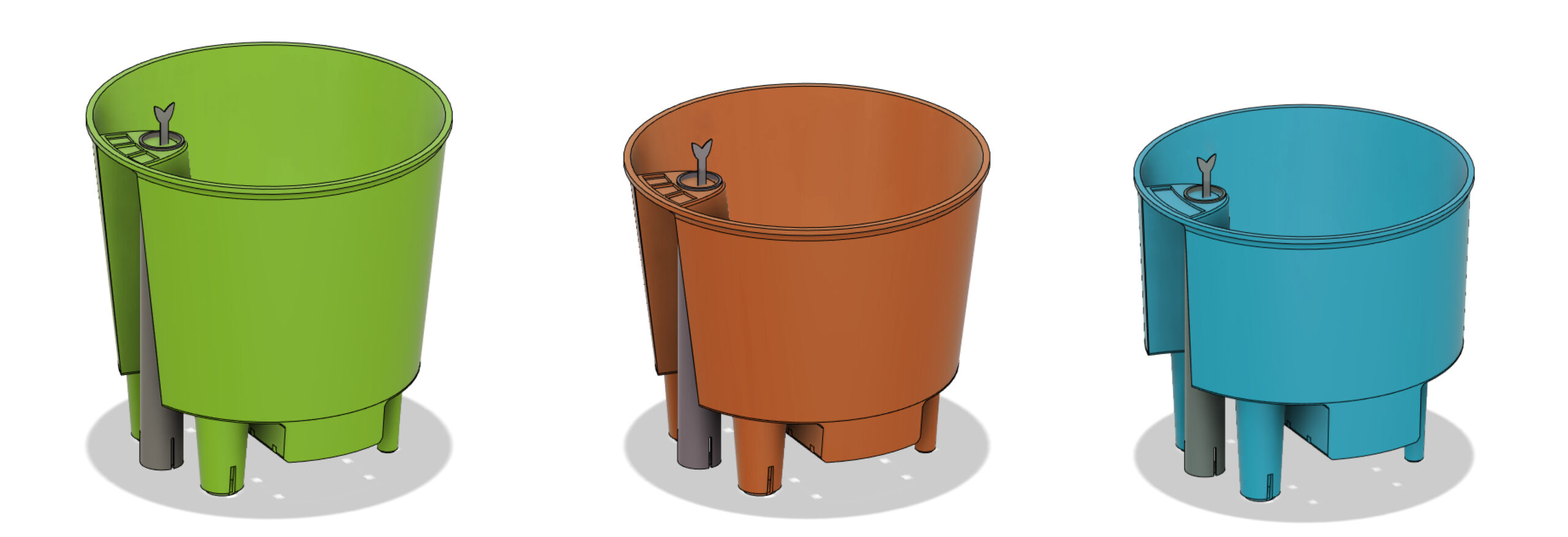
3 different self-watering plant pot inserts generated from the same Fusion360 design
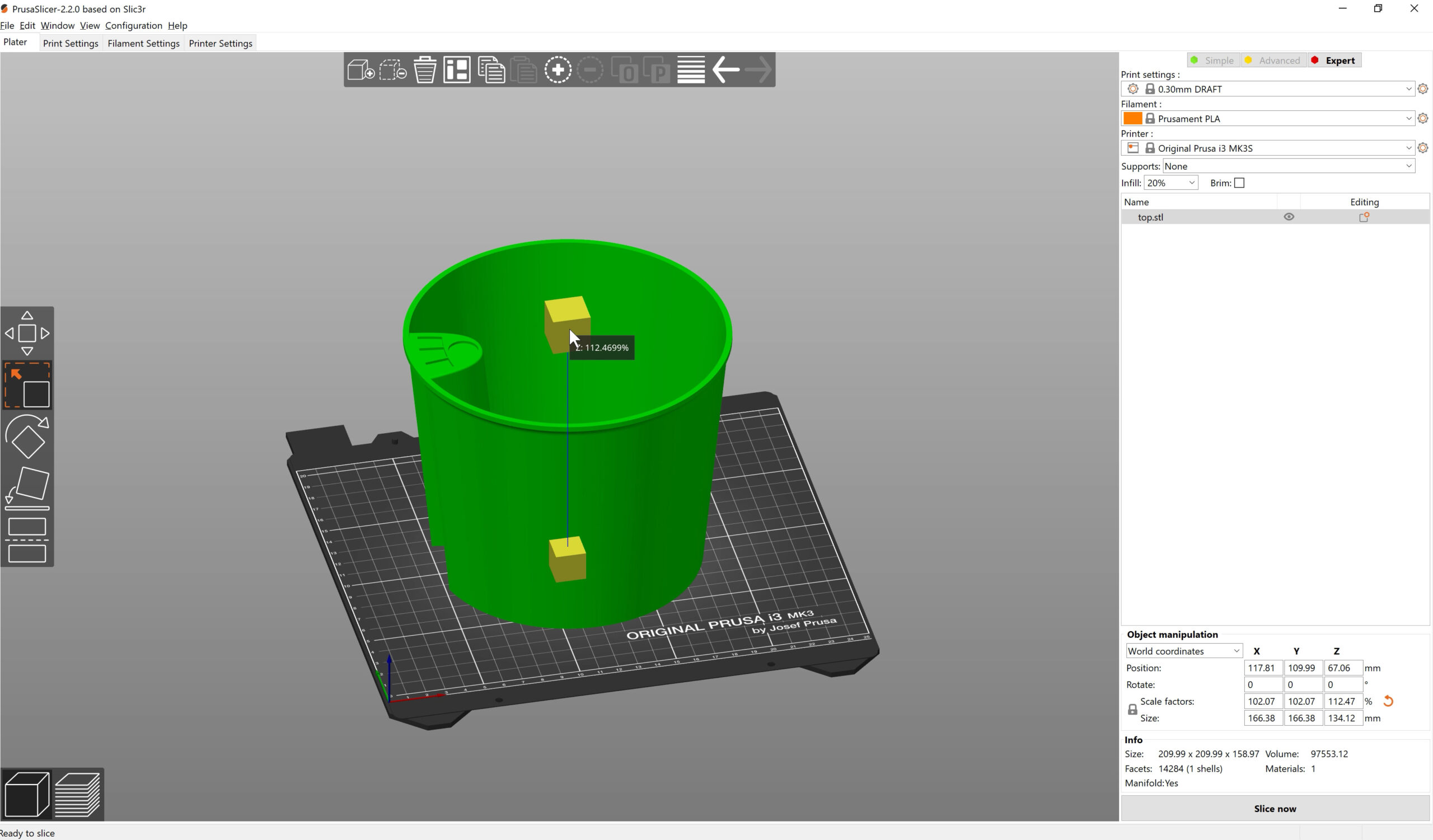
Scaling the model (STL) in the slicer
Your first option is to simply re-scale the exported STL in the slicer. This will work if the size difference is fairly small. Because you’ll also be scaling all tolerances, the wall thickness. So at some point, parts of the model will be either too small to be printable, or if you scale it up, unnecessarily thick and tolerances too loose. There is only so much you can do with simple scaling, What if the pot has a bigger difference between the top and bottom diameter? Scaling is not flexible enough for such a case.
Changing the dimensions manually
The second option is editing the dimensions manually in Fusion360. This sounds easy, but even this shape-wise relatively simple model has 18 sketches and dozens of steps in the Design history timeline.
If you, for example, change the height of the pot in the very first design step, it will most likely create errors in the following operations. E.g. if you decrease the height from 140 mm to 120 mm, but later on you do a full height chamfer, it’s still set to chamfer the old value of 140 mm, which is invalid.
You will most likely have to go through the individual design steps one by one and re-write the value everywhere. Again, this might be fairly painless with very simple models. But with complex models, you might find it nearly impossible to fix all the errors.

Unsuccessful change of model’s dimensions
Using parameters
In this case, before you start designing anything, open the Parameters window, and set up a few parameters. You can re-open this window at any time and add more parameters, when necessary. These parameters will typically be real-dimensions of an object that needs to fit together with this part. Or things you might want quick and easy control over, such as the wall thickness, hole diameter, etc.
Examples of commonly used parameters:
- Width
- Height
- Wall thickness
- Hole diameter
- Fillet diameter
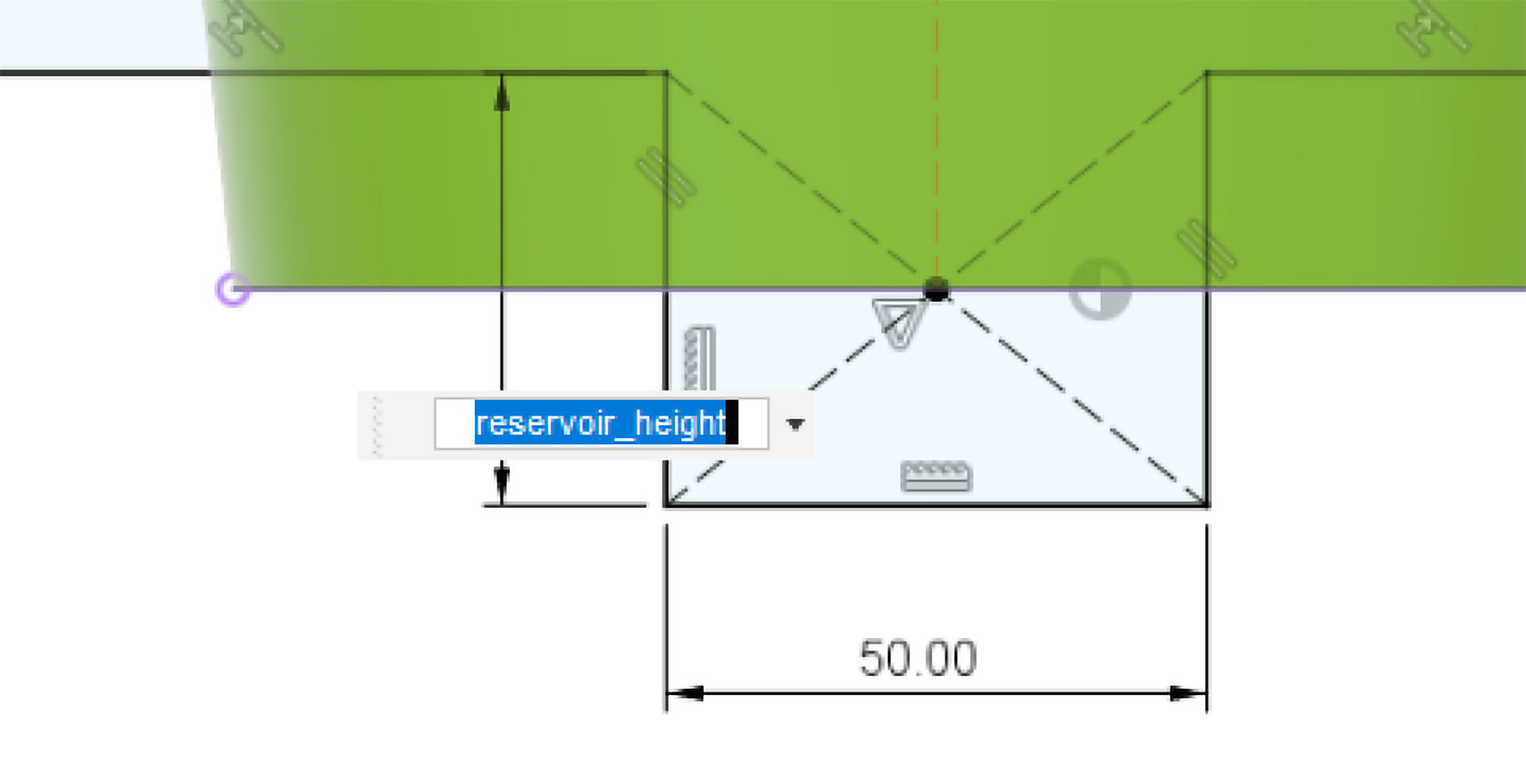
Then when you’re defining dimensions of a feature, simply write the parameter name instead of the exact value. Fusion360 will even auto-complete the names for you.
Another thing that you should keep an eye on, is sketch constraints. If you know, that a line should be vertical, make sure it is set that way. Should two lines in sketch be perpendicular to each other? Add the constrain.

Depending on how well you set the model up, changing the dimensions might be as simple as going into the parameters window and adjusting the values there.
Some clean-up might still be necessary, it can be tricky to set the constraints in a way that allows for a wide range of parameter values. But it should definitely be way easier compared to not using parameters at all.
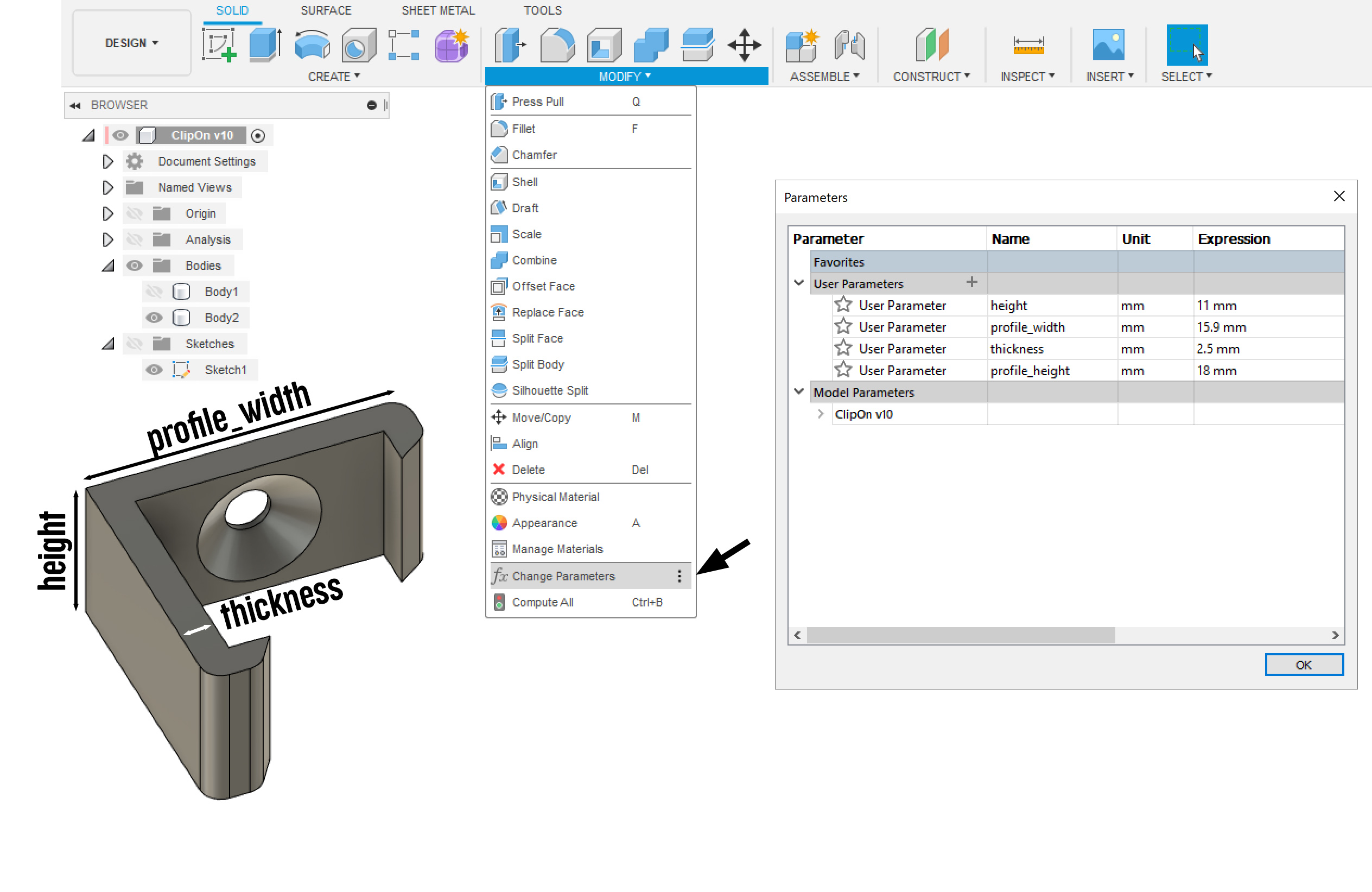
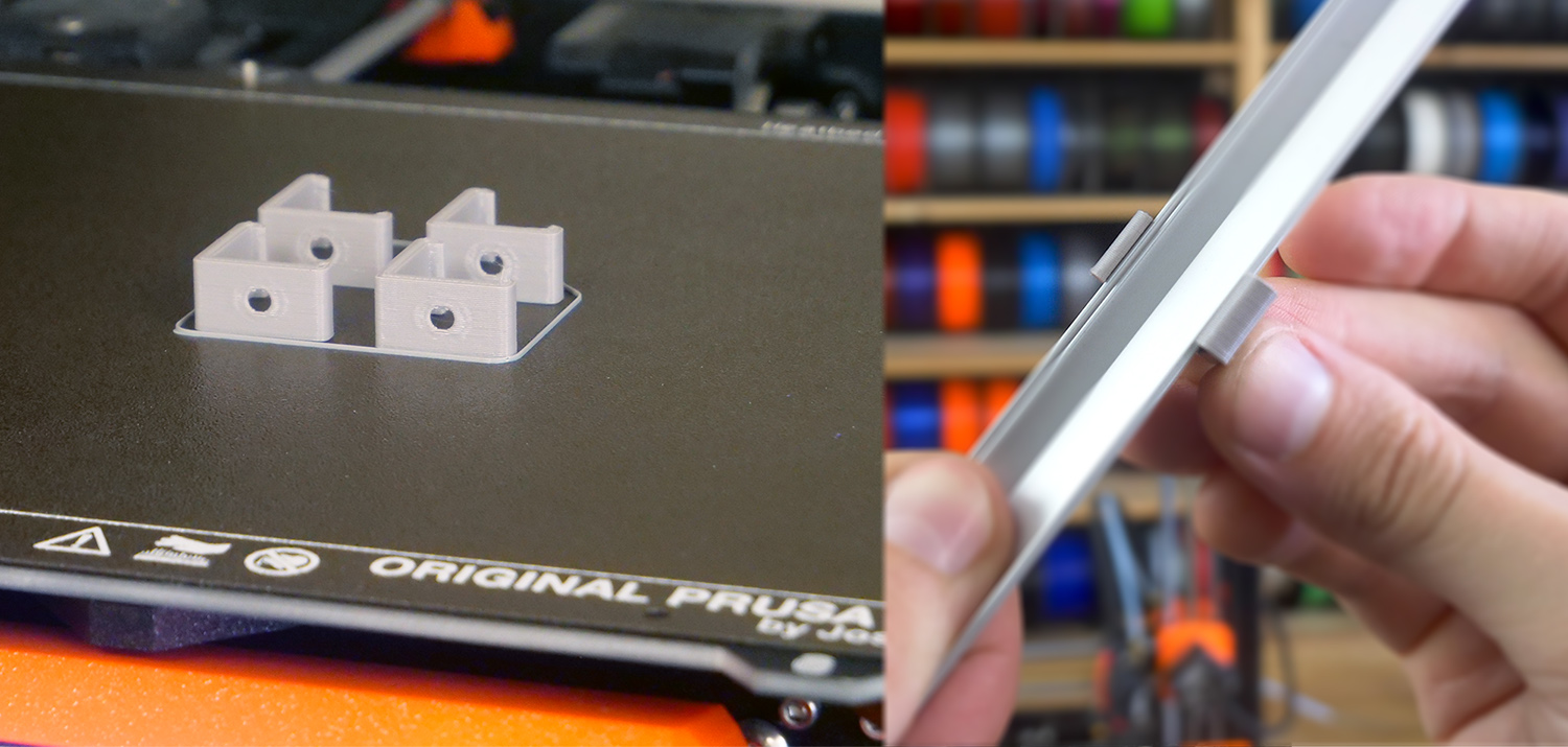
Example 2 – wall-mounted LED profile holder
Using just 5 parameters, this model can be easily customized from the parameters window.
If you wanted to adjust it for a different LED profile, all you have to do is measure ain input the two dimensions:
- profile_width
- profile_height
If both sides of the profile have the same length, you can simply input “profile_width” as the value of “profile_height”.
And then we’ve used 3 values to have full control over the clip shape:
- Height
- Thickness
- Hole diameter
 Parameters in Fusion360 are very similar to variables in OpenSCAD. But OpenSCAD isn’t exactly user-friendly, so it’s good to know that Fusion360 has similar functionality.
If you want to share your parametric design, for example, here on PrusaPrinters, you can use File – Export, pick the Fusion360 archive file format (.f3d) and upload it together with your 3MF/STL/GCODE files. When others open this file, they will still be able to access and change the parameters.
Happy printing!
Parametric model are so powerful !!!
Once you get used with them they are a time saver to produce quality models.
Here is another take on what can be done.
https://www.prusaprinters.org/prints/26496-covid-19-coin-ball-decor
Nice tutorial!
Where can I find the model for the self-watering pot?
Wouldn’t it be really handy to have exactly such a model of a parametric self-watering pot insert? Especially during the holiday time.. downloads would go crazy. But I can’t find it anywhere – i wonder why
Thank you so much for this! I was just telling a friend how I wished I better understood features like these. I’m really hoping you keep doing these instructional vids, as they are a huge help!!
Thanks,
I’ll try to do another one in the future 🙂
I used parameter as the number of slots on my USB Cables Wall Hanger. You can create parameter without any unit, and used it as a multiplier inside features or sketches. https://theveel.com/3d/3dprinted-usb-cables-hanger/
Definitely a huge leveling up when one designs like this. The phrase de jure at the time was “parametric solid modeling” … ie this was the main point. Fusion360 is certainly a great product as well on the technical/feature level.
However, from the recent licensing changes, Fusion360 is hardly compatible/friendly to the maker movement, much less a (fantastic!) company committed to open source such as Prusa.
It would be MUCH more interesting & relevant IMHO to cover this topic for FreeCAD or similar more open products. Thanks!
Thanks Mikolas!
I used Parametric Design in FreeCAD and now I started using Fusion360. Is there anyway in Fusion360 to leave the Parameters Dialog window open during the design process? With FreeCAD I had the Spreadsheet, aka Parameters Dialog, open in a small window so I can see the variable labels quickly during the design.
Cheers and keep making your great videos and howto!
Nikos
You explain this so clearly – thank you
How exactly do I import a parametric file in (what file format) to fusion? I'm not proficient in fusion at all.