


You may have noticed that there are new infill patterns in our new version of PrusaSlicer (2.3). Now, with the sheer amount of options, you might even feel overwhelmed with all the possibilities. Which infill should you choose? Is there a single universal pattern that works for every model? Or should you pick depending on a specific case? Let’s take a look at what can be accomplished by using the right kind of infill and adjusting its parameters.
Infill: inner structure of your 3D prints
First, let’s do a quick recap of what an infill is and why it is important. If you are a 3D-printing pro, you may want to skip this chapter, but it never hurts to brush up on the basics, right?
3D printed models are rarely printed solid (100% infill) or completely hollow. Instead, we use a method that fills the inside of an object with a sparse supporting structure. Infill provides internal support for top layers, which would otherwise have to bridge over empty space. This helps keep the model solid and prevents gaps and holes from appearing on the object’s top surfaces. Solid models (100% infill) consume large amounts of filament and time. Also, in most cases, solid models won’t provide better mechanical properties compared to models with a sparser infill. If you decide to print a model without an infill, you’re risking that the surface of angled walls and top layers will be compromised – there might be small gaps or even large holes. It’s pretty much obvious that the best solution lies somewhere in between. With proper infill settings, you can save a lot of material and time but also create some interesting patterns on the surface.
Most of the time, it makes very little sense to set the infill density higher than 40 %. Our testing revealed that the best density setting is 10-20%, and we implemented this value in our PrusaSlicer profiles. 10-20% is the ideal balance between strength, print reliability, print time, and material consumption. Of course, for some objects, a 5% (or lower) infill might be enough, especially large simple parts printed with PLA. With density higher than 20% comes higher tenacity. However, the same effect can be achieved by adding more perimeters as well (Print settings/Layers and perimeters). With different print settings, you can change not only the internal structure and mechanical properties but also print speed, material consumption and the object’s surface.
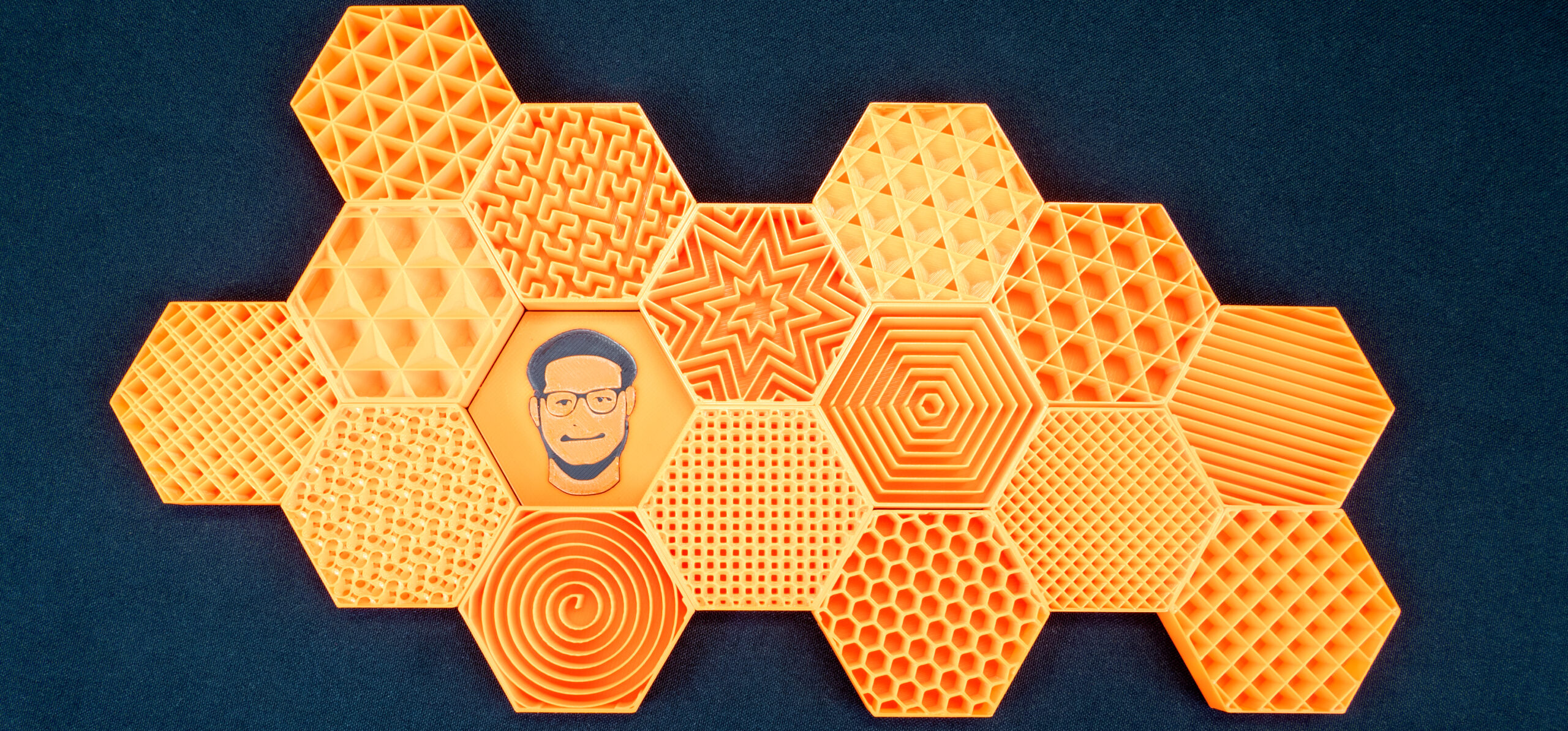
Before we start with advanced settings, let’s take a quick look at all available types of infills and their properties one by one.
Infill types and their properties
The list of infills has grown a lot and it might be difficult to choose the right type. Although you may feel they differ mostly in appearance, the opposite is true. For example, some infills may save us a lot of material and time, some can be filled with liquid, etc.
Rectilinear
Rectilinear is one of the basic infill patterns. It creates a rectilinear grid by printing one layer in one direction, the next layer rotated by 90°, etc. This way, it saves filament and doesn’t accumulate material at crossings (unlike grid). It’s one of the fastest printed infills.
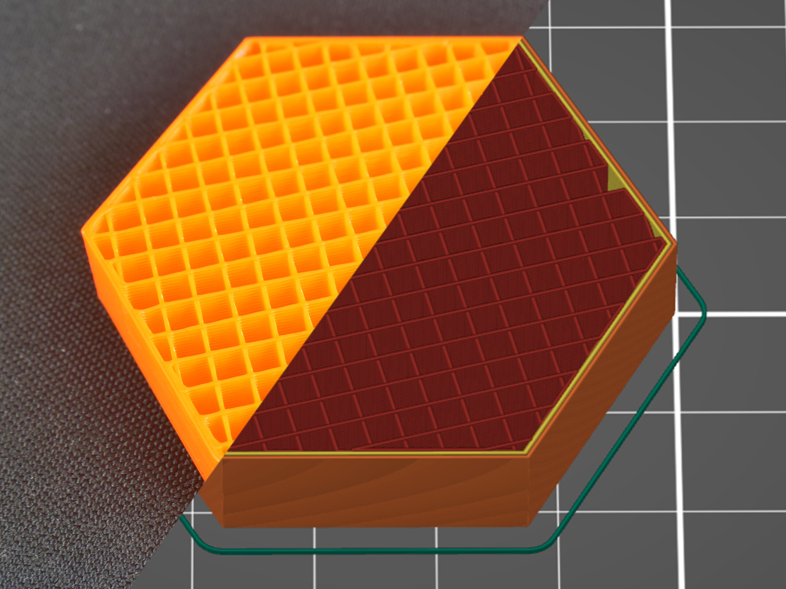
This type of infill is the only one recommended for 100% infill printing. If you have another type of infill set in your profile and change the infill percentage to 100% density, PrusaSlicer will automatically change the infill type to rectilinear.
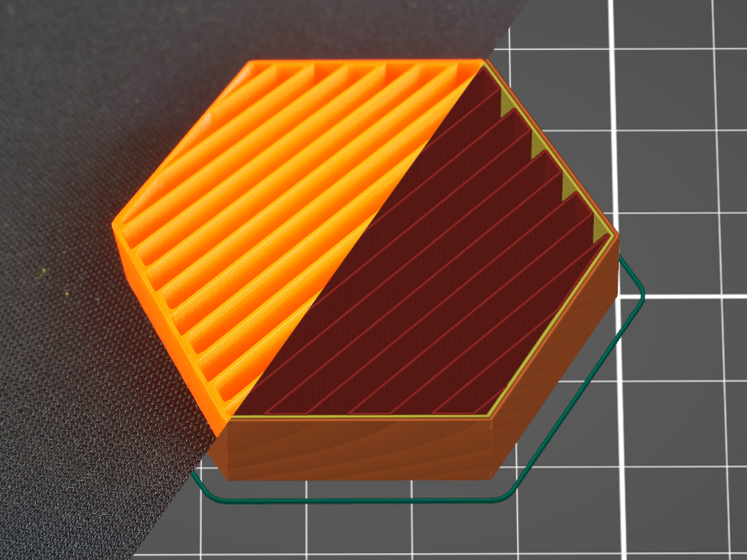
Aligned rectilinear
This infill is formed by parallel lines drawn inside the model, which resemble the outside support structures. Similar to the previous type, this infill saves time, has average material consumption, plus it doesn’t accumulate material at crossings. However, using this infill might cause some trouble when the direction of the lines in the infill is the same as in the infill of the first top solid layer – if they are perfectly parallel, the top layers might have issues with bridging.
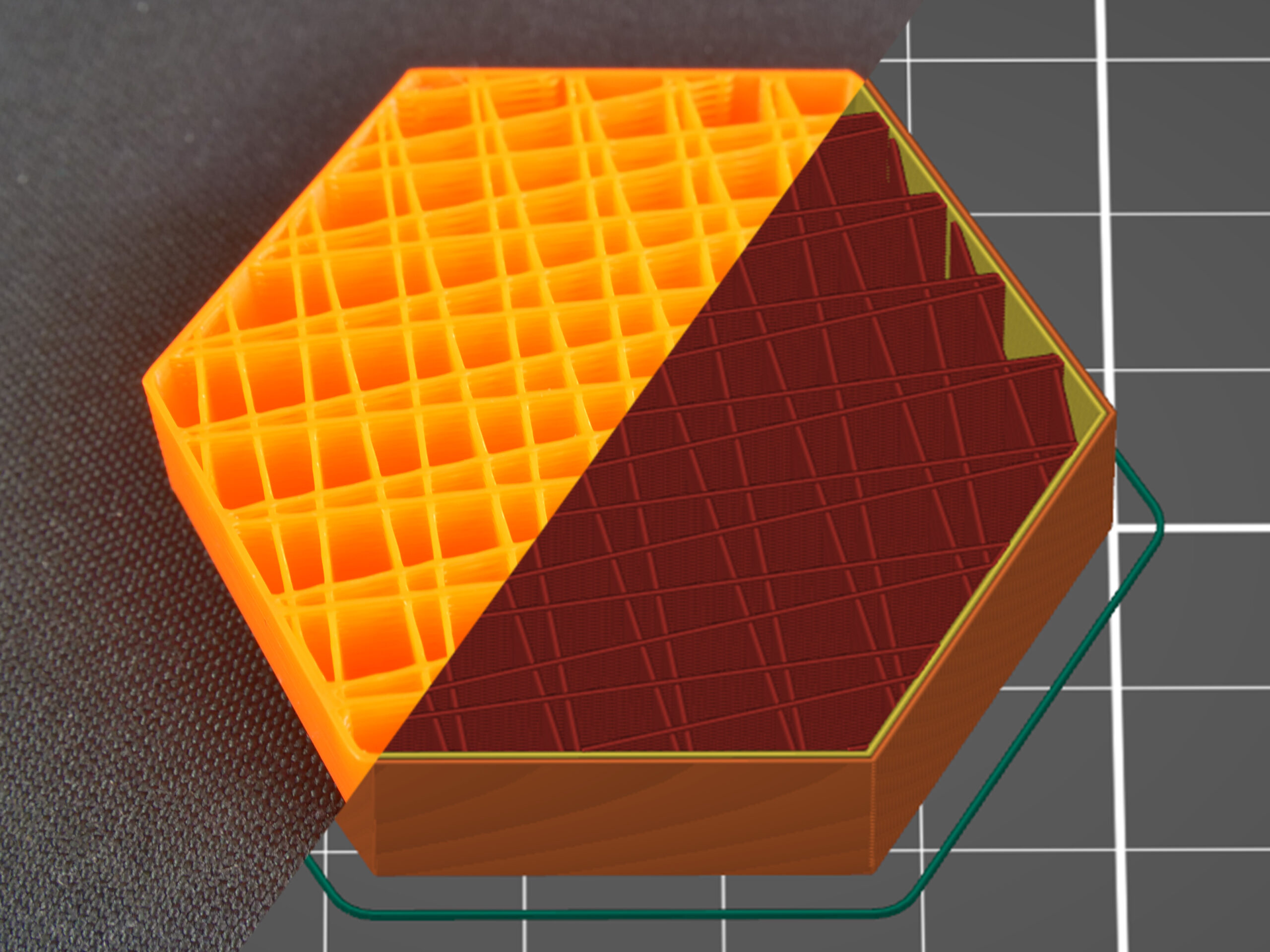
Grid
This is one of the simplest and fastest variants of infill. Unlike rectilinear, it’s printed in both directions (rotated by 90°) in each layer. This way, material accumulates in spots where the paths cross. The grid infill is more solid (and has better layer adhesion) than the rectilinear infill, however, it sometimes can cause annoying noise or even a print failure due to the nozzle going over the crossings where material accumulates.
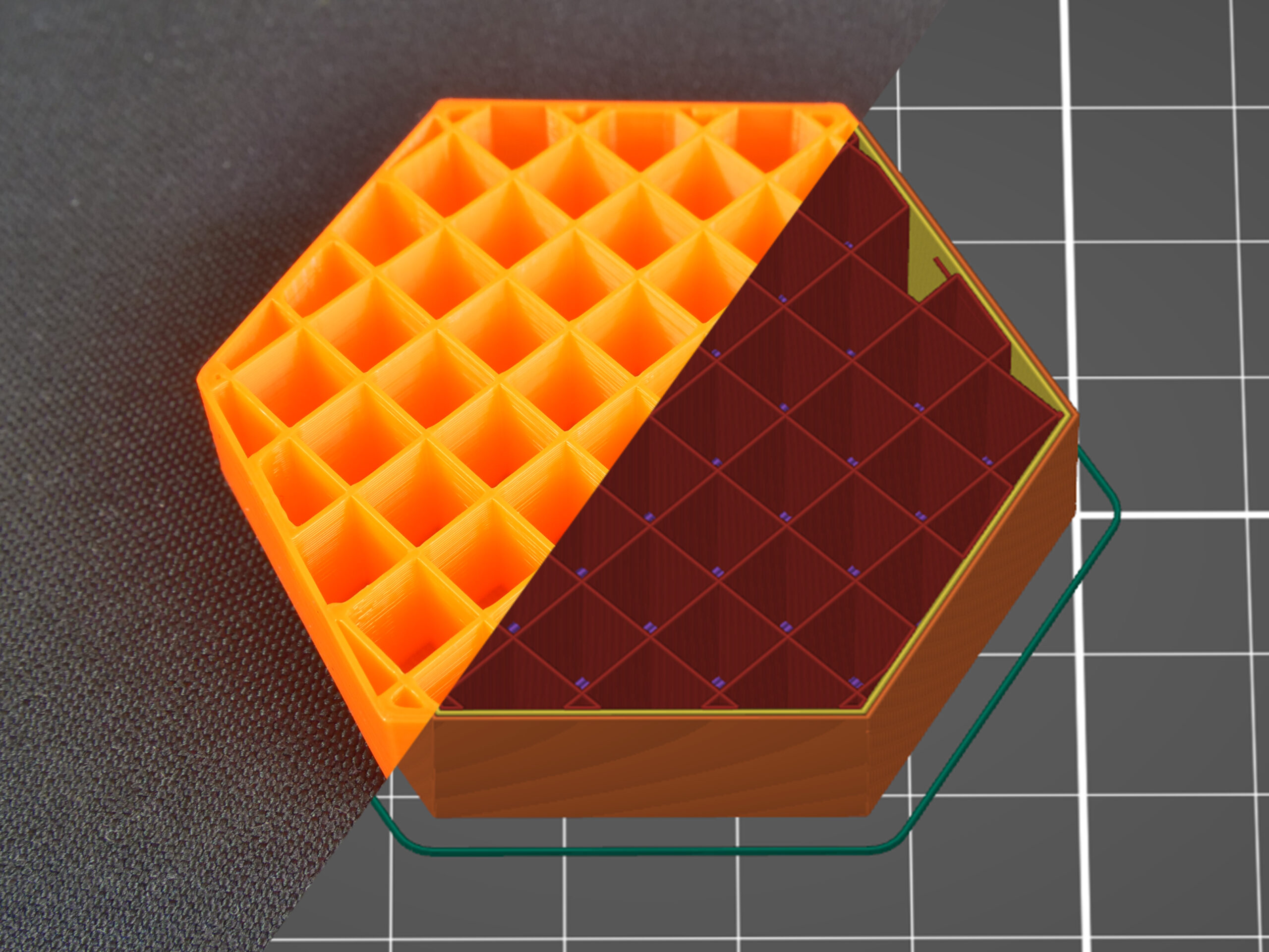
Due to the way this infill is printed, the paths cross and cause the material to accumulate in these spots. You may hear a specific noise as the nozzle hits these parts. This may even lead to a failed print.
Triangles
This infill works similarly to the grid infill – the paths cross in one layer, however, this time they are printed in three directions and form a triangle structure. Material and time consumption is almost identical to the grid.
Stars
The Stars infill is based on triangles but paths are shifted to make six-pointed stars. Again, this infill is created by lines that cross each other within a single layer. Material and time consumption is similar to the previous infill.
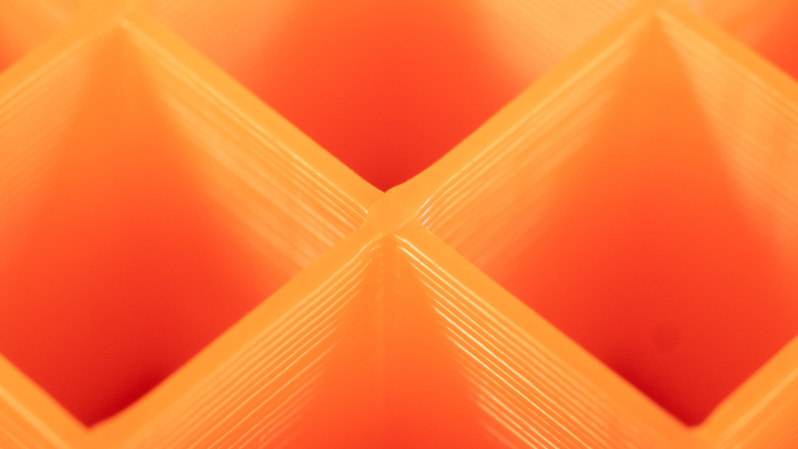
Cubic
Again, this is an infill with paths that cross each other within one layer. However, unlike previously described infills, it creates cubes oriented with one corner facing down. This way it makes numerous air pockets that might serve as heat insulation, or cause the object to float on water (with waterproof filaments such as PETG). Print time and filament consumption does not differ from the previous infills.
Line
The Line is one of the infills that don’t feature any crossing paths in one layer. Its paths are similar to the rectilinear infill but they are not parallel to each other. Instead, they are printed at an acute angle. Unsurprisingly, this infill is similar to rectilinear when it comes to printing time and material consumption.
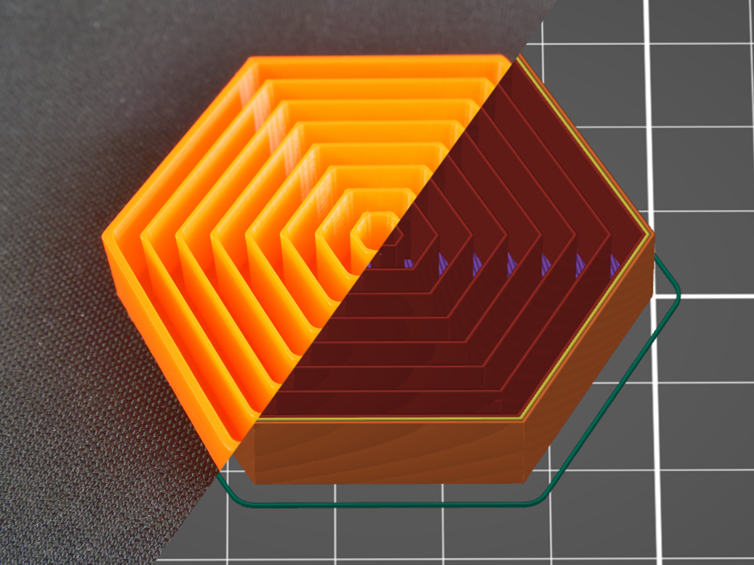
Concentric
The concentric infill traces the model perimeter lines and makes them smaller towards the center. In other words: if you print a cylinder, the concentric infill will create concentric circles inside that cylinder. This can be useful with transparent parts or flexible models (RC tires for example). The main disadvantage is the time spent printing. Material consumption is not higher than previous types of infill patterns.
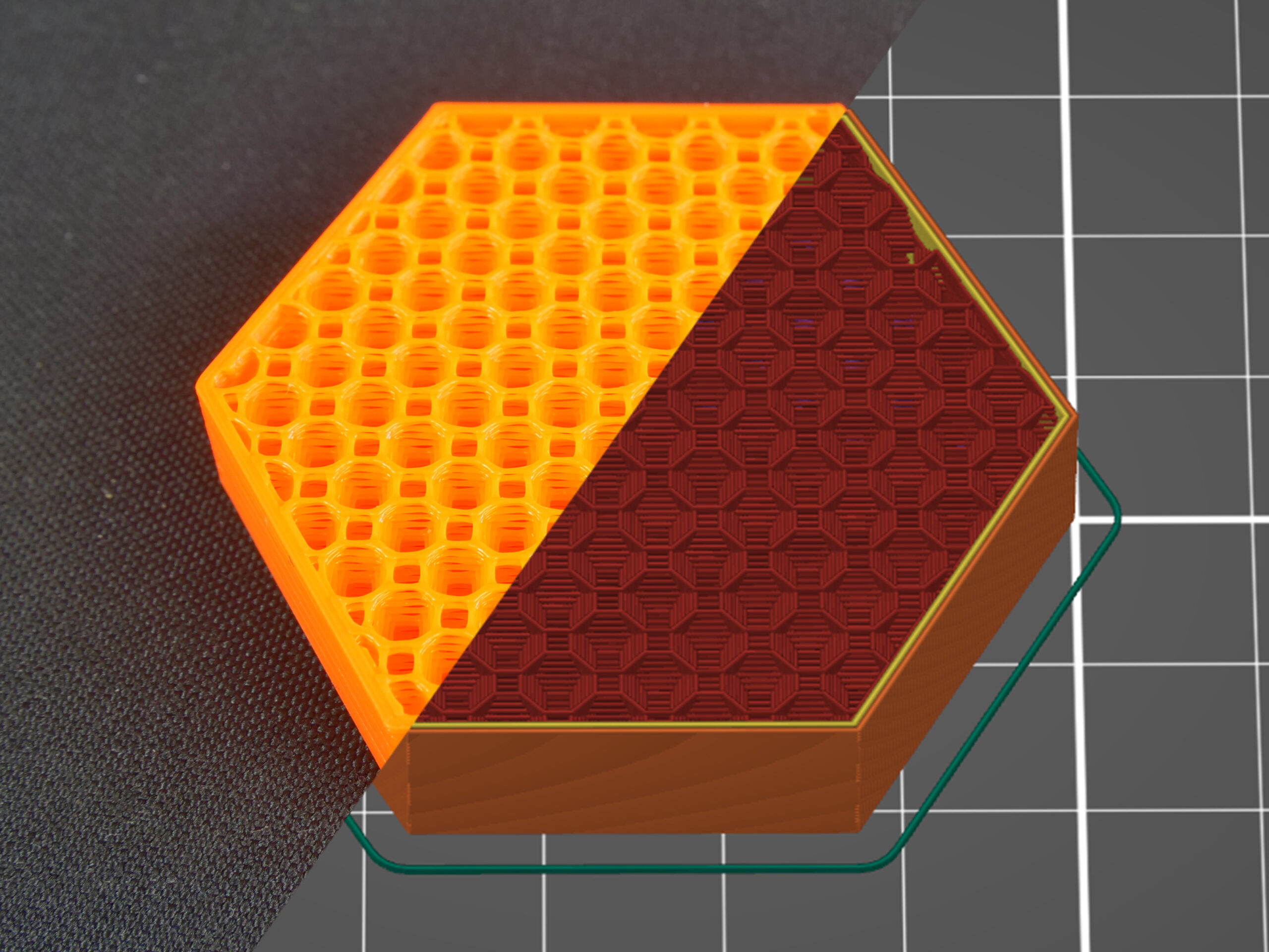
Honeycomb
This infill prints a grid made of hexagons. Its main advantage is mechanical resistance and optimal paths without crossings. The main disadvantages are higher material consumption (approx. 25% more) compared to other infills, and print time that can take up to twice the time of previously described options.

3D honeycomb
3D honeycomb prints bigger and smaller squares and octagons to create columns of periodically increasing and decreasing thickness. Again, this infill doesn’t have crossing lines in one layer, however, due to the way it lays down the paths, it creates small gaps between layers. Material consumption and print time are slightly worse compared to the regular honeycomb pattern.
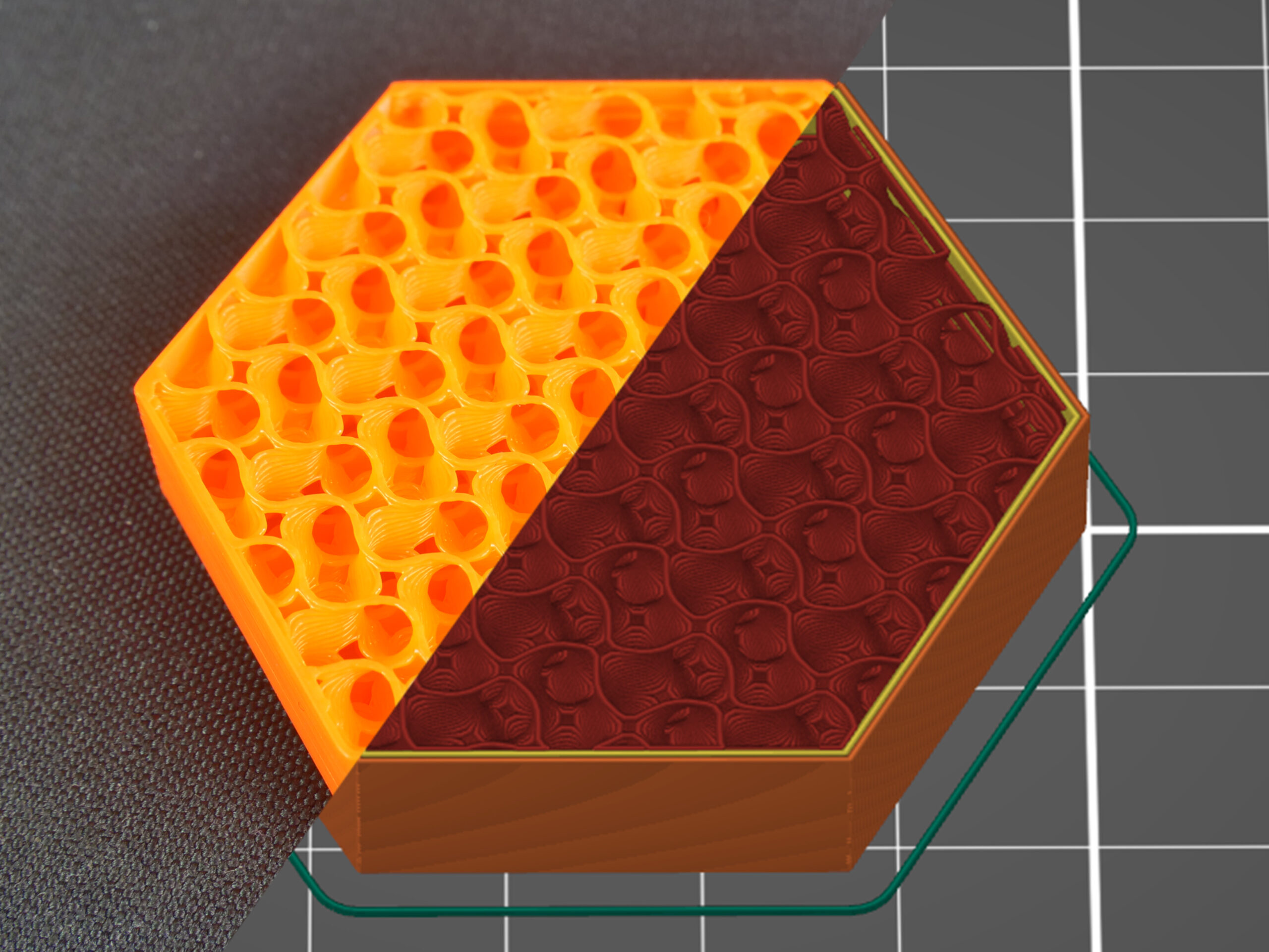
Gyroid
The Gyroid is our favorite and one of the best infills. It’s one of the few 3D structures that provide great support in every direction. Plus it’s printed relatively fast, saves material, doesn’t have crossing lines in one layer and looks great. The special shape of this infill allows filling it with epoxy resin or another liquid.
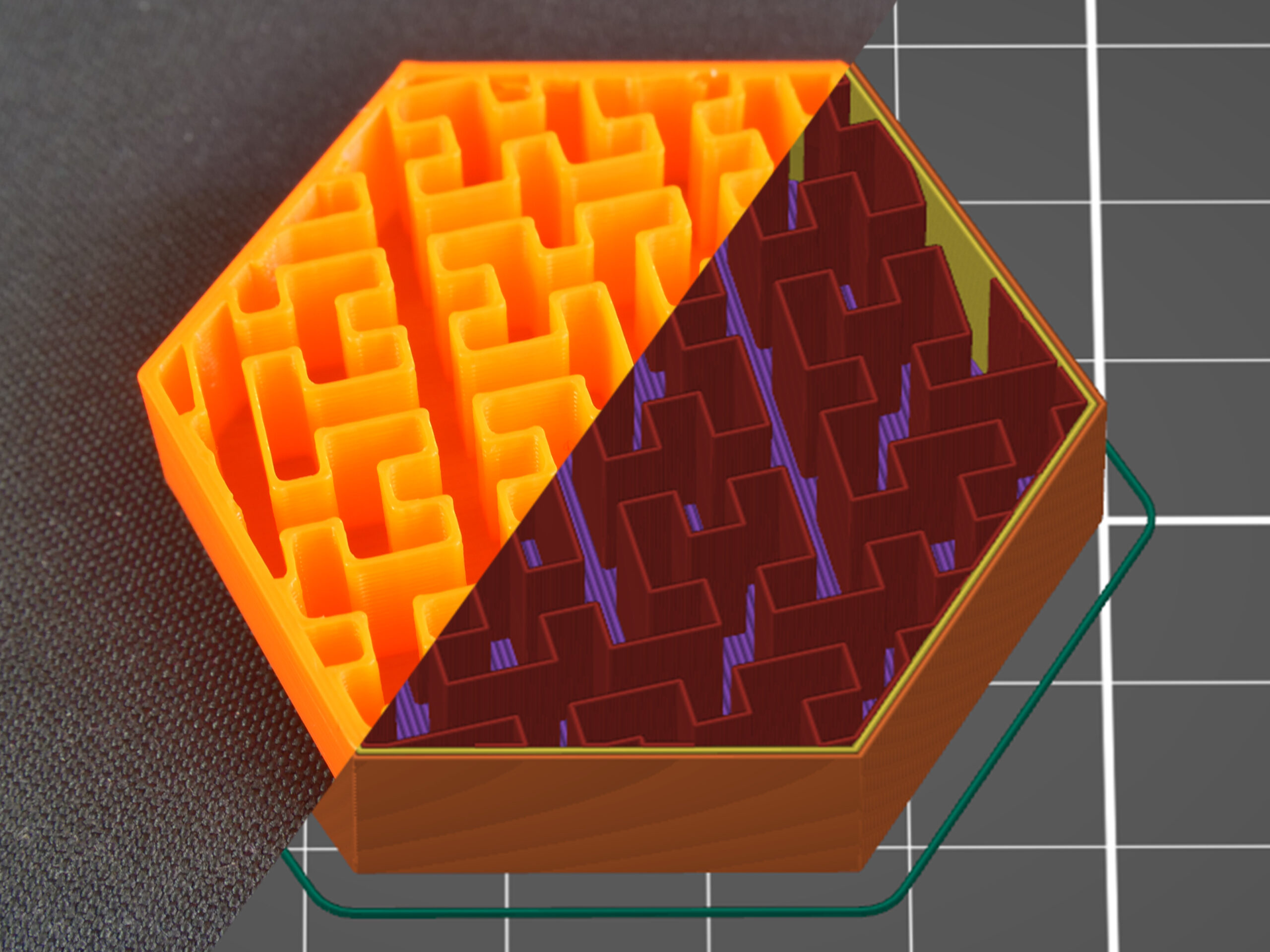
Hilbert curve
The Hilbert curve creates a rectangular labyrinth inside the model. The main advantage of this infill is its non-traditional look, plus it can be pretty easily filled with epoxy resin or another liquid – the model is split into several large cavities, instead of a number of small “bubbles”. The main disadvantage of this infill is increased print time, which sits somewhere between honeycomb and rectilinear infills. The material consumption of the Hilbert curve is similar to the rectilinear.
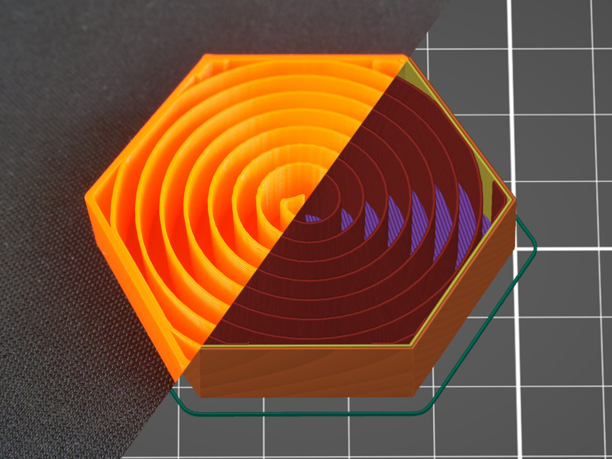
Archimedean chords
Again, this spiral-twisted infill allows easier filling with liquid. This simple shape saves material and time (compared to the rectilinear infill). Similar to the concentric infill, the Archimedean chords help with model flexibility if you print it with flexible filament.
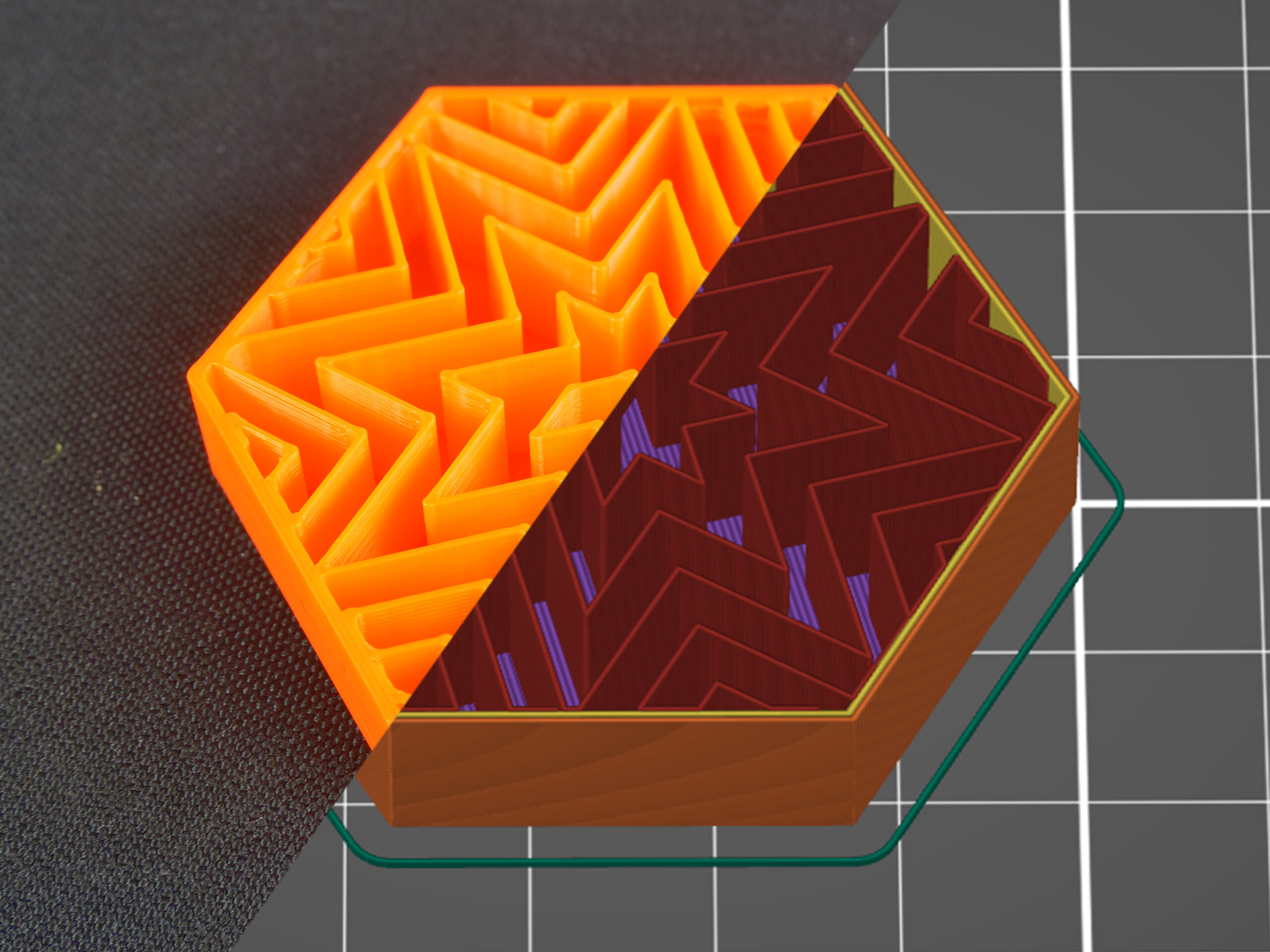
Octagram spiral
Octagram spiral allows filling the object with liquid easily due to larger compartments made with this type of infill. An Octagram spiral might also help with flexibility for certain models. But mostly it’s for aesthetic purposes and top layer support. Material consumption is similar to Archimedean chords but print time is slightly longer.
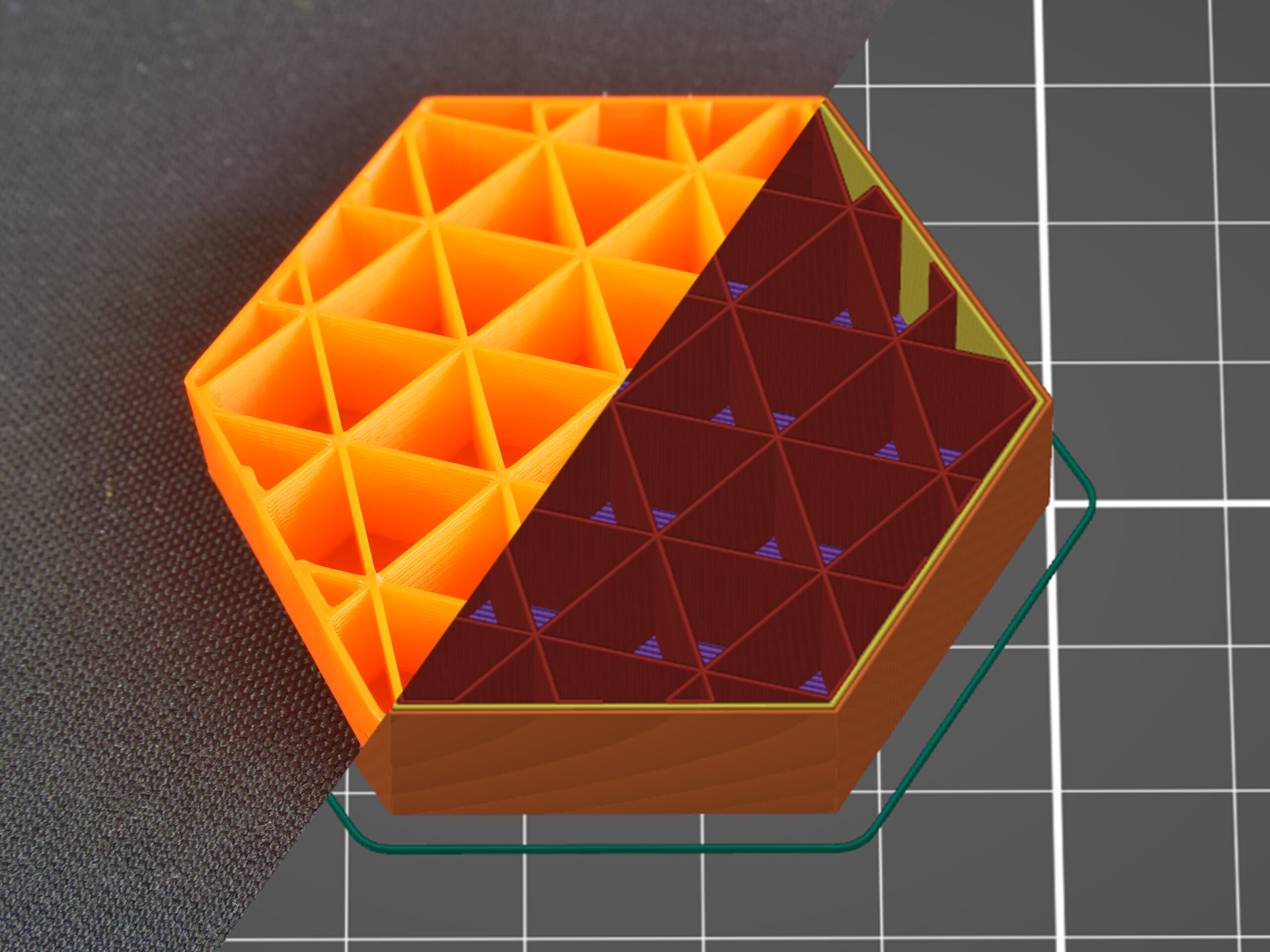
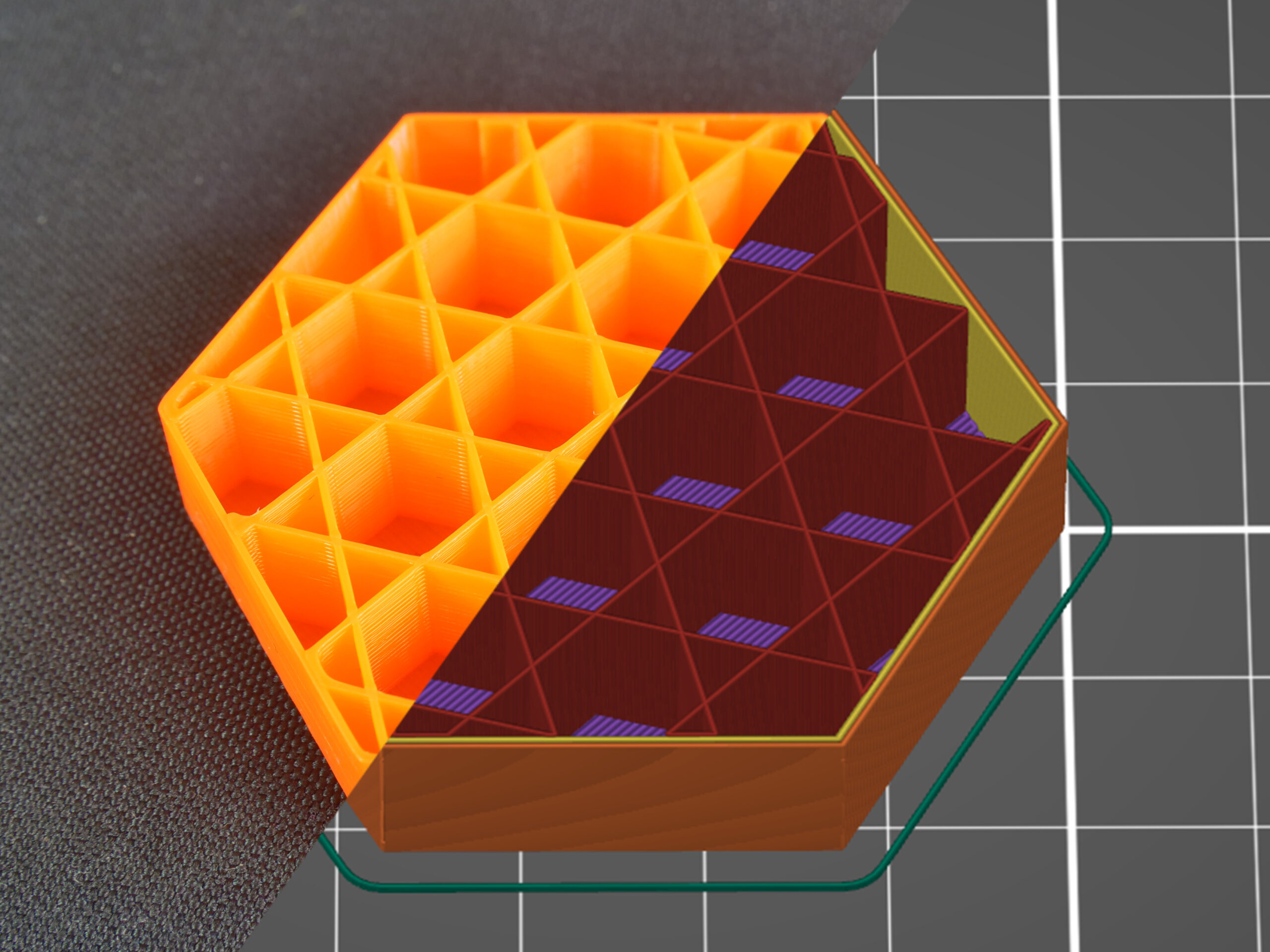
Adaptive cubic
The adaptive cubic infill works on the same principle as cubic: It consists of cubes oriented corner-down where lines cross themselves in one layer. But there’s one great advantage: Unlike a simple cubic infill, this pattern makes the infill denser towards the model edges, leaving large cavities in the middle. Material consumption is approx. ¼ less than the rectilinear infill.
The Adaptive Cubic infill works by refining those cells of an octree, that contain any object triangle. Anchors are added to each infill line. This makes the infill sturdier and it stabilizes the extrusion flow at the start of an infill line. Basically, This infill gets automatically more or less dense, depending on the distance to the nearest wall. This is especially useful for large prints with a big internal volume. The result is shorter print time and lower filament consumption while maintaining great support for top layers and similar mechanical properties.
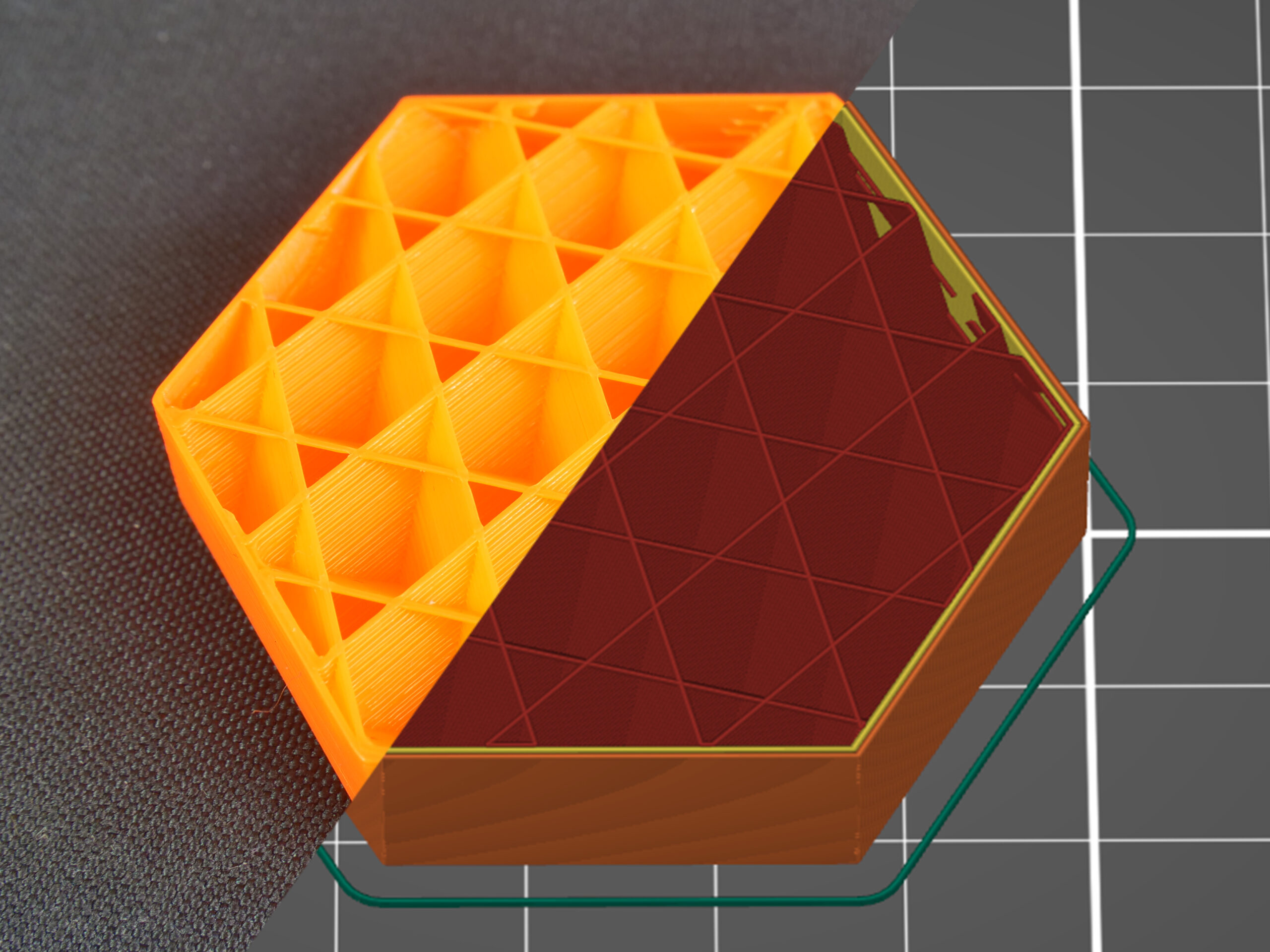
Support cubic
The support cubic infill works similarly to the previous type but with one difference: the infill density increases only in the Z-axis. Its primary function is to support top layers by saving as much material as possible, it doesn’t improve any mechanical qualities of the model. Material consumption and print time of this infill are by far the lowest of all the supported infills.
Types of top (bottom) layer infill
Editing infill doesn’t end with choosing an infill type for the internal parts of the object. You can also change top and bottom layer infill types to get some interesting results. These can be adjusted in the Print settings/Infill/Top (Bottom) fill pattern tab. However, changing the top or bottom infill mostly affects the aesthetic changes and does not improve the mechanical properties of the model.
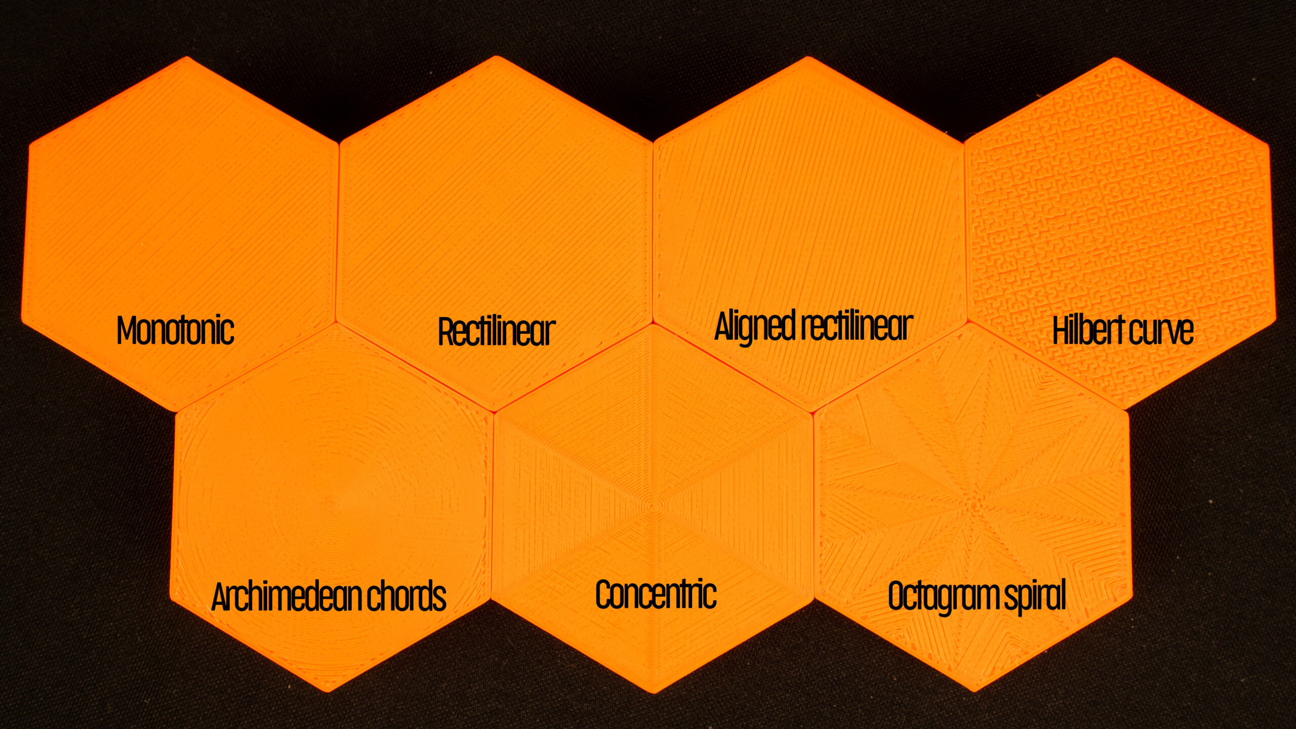
All seven types of the top (bottom) infills printed with 80% flow to highlight the patterns.
Rectilinear
Again, this is one of the most common (and basic) types of top infill. The print paths are oriented zig-zag for the whole layer. However, this is the simplest type of infill that doesn’t provide any advantage whatsoever (see Monotonic infill).
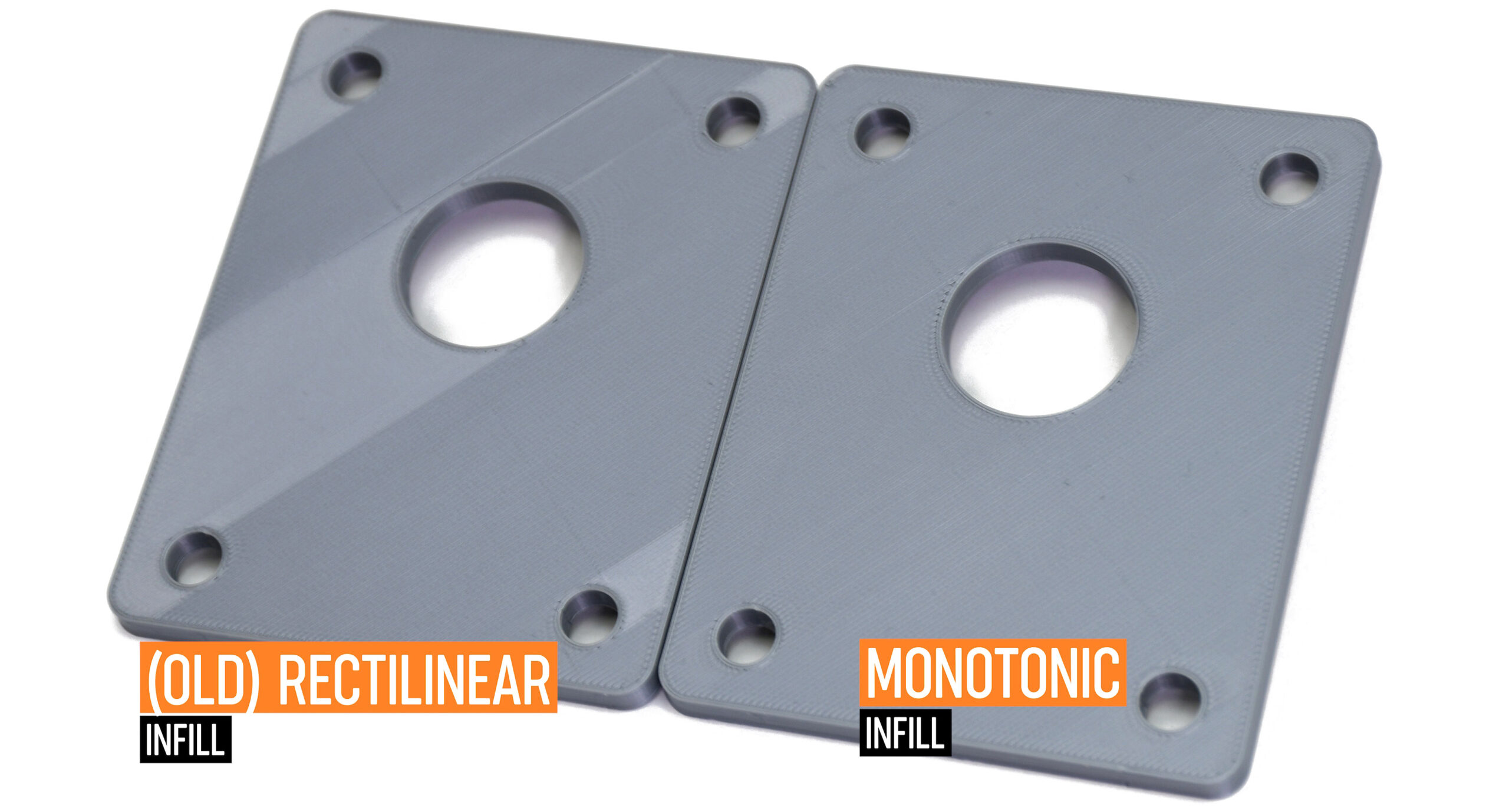
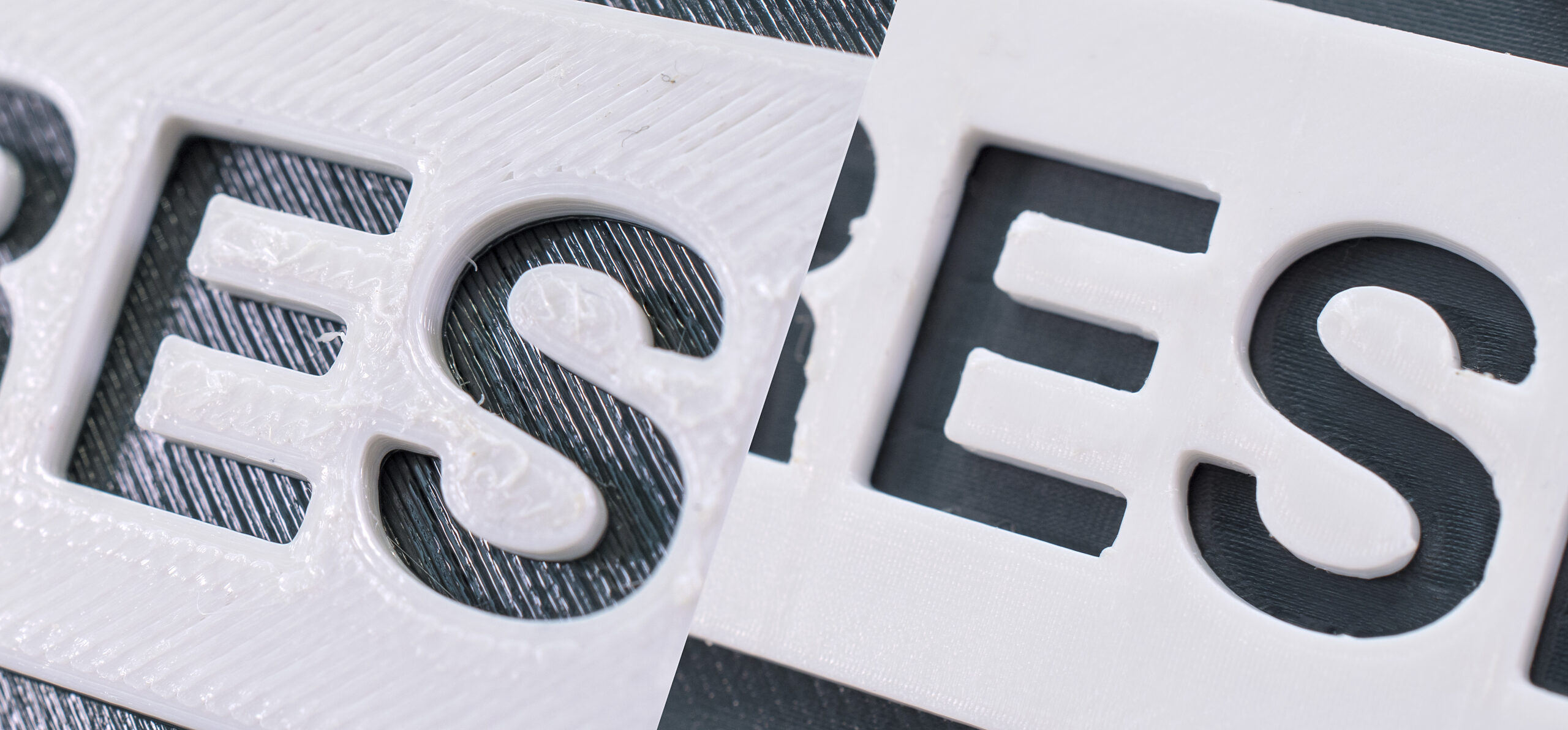
Monotonic
The monotonic infill pattern fills the top (bottom) layer with parallel lines, similar to the rectilinear infill type. However, this infill works with advanced path planning. Unlike rectilinear, this infill is always printed left to right and never in the opposite direction. This simple system leads to achieving a homogenous infill without ugly ridges. These usually appear with other infills when left to right paths meet the right to left ones. This seemingly simple method is surprisingly hard to implement. We used the Ant Colony System variant described by Raad Salman.
Aligned rectilinear
This infill pattern works similarly to the rectilinear infill but the last layers on all top surfaces are aligned in the same direction. This can help for creating a homogenous top layer pattern for models that have top layers in different heights (imagine a staircase model).
Concentric
The concentric infill pattern copies perimeter shapes. If you print a cylinder, it will create concentric circles on top of the model.
Hilbert curve
This is mostly an aesthetic infill. If it’s printed inside, Hilbert Curve creates rectangular shapes, while the topmost layer looks more like a wicker basket. Some people say that it looks “wormy”. This infill significantly increases the print time due to the complex shape.
Archimedean chords
The topmost layer of archimedean chords is printed in a spiral. This infill can save time when printing certain models.
Octagram spiral
Again, this infill is described above. It’s good mainly for aesthetic purposes but due to the complex shape, it prolongs the print time.
Advanced settings
PrusaSlicer lets you adjust infill patterns even more! If you switch to the Advanced or Expert mode, you’ll find a lot more settings in the Infill tab. Let’s take a look at all the settings related to infills, regardless of whether it’s in Advanced or Expert mode:
Length of the infill anchor
The infill is usually connected to the perimeters with a so-called anchor, which is a short line of another (inner) perimeter that turns into an infill line. The length of the infill anchor value sets how many millimeters of this anchor will connect the infill and the perimeters. If you set this value to 0, the infill will be printed independently on the perimeters. Set a higher value to print the anchor that will continue as the infill itself. The infill anchor helps to increase model integrity and toughness.
The maximum length of the infill anchor
This value sets the maximum length of the infill anchor connecting the infill with perimeters.
Ironing
Ironing creates a smooth top surface on horizontal planes – filament paths are almost invisible. How is this achieved? The hot nozzle goes over the surface one more time but with low filament flow. Turning the ironing on or off, and/or choosing the ironing type (all top surfaces, topmost surface only, all solid surfaces) should be enough for most 3D printer users. However, some may want to tweak the flow rate or spacing between ironing passes. The flow rate is set as a percentage linked to the normal layer height, the spacing between ironing passes tells how far the parallel nozzle tracks should be from each other. These parameter values are set to optimal values, but you can experiment with them as you wish if you are not happy with the results.
If you increase flow, you risk that material leftovers will remain on the surface. Also, the nozzle tracks may remain visible. Lower flow, on the other hand, will leave the last layer paths visible due to a lack of material filling the gaps.
Spacing between ironing passes has a great influence on the top layer visibility too. To make it a bit easier to imagine, we’ll compare it to a snowplow. Let’s say you use only a part of the plow blade to clean off the snow – it will remove some amount of snow and clean the plowed part of the road, too. However, if you dig the entire plow blade into the snow and move forward, you’ll create a path, but there will be excess snow left behind.
To find out more about ironing, read our older article.
Reducing printing time
PrusaSlicer offers two variants of saving time and material. The first option is combining infill every X layers. The default value is set to 1, where every perimeter layer is printed with one infill layer (1 = ratio of 1 infill layer per 1 perimeter layer). Increasing the value to 2 (2:1 ratio) will print one layer of infill (of according layer height) for every two perimeter layers. But keep in mind that this value cannot be increased infinitely. PrusaSlicer will let you set it very high but the only maximal physically possible value will be written into G-code. To be specific: If you use a 0.4mm nozzle and 0.15mm layer height, the slicer won’t let you print one infill layer less often than every two perimeter layers. Otherwise, the infill would be printed to empty space. But if you print with 0.05mm layer height (0.4mm nozzle), you can combine infill every 6 layers (maximum layer height is 0.3mm).
The second variant of saving time (and material) is printing infill only where needed. For example, if you print a sphere, this function will make only an infill column in the center to support possible overhangs. The main disadvantage of this function is low denting resistance due to the lack of infill in some model parts.
Advanced
These infill settings are truly advanced stuff and most 3D printer users won’t even come close to ever needing them. However, there might be some special cases when you’ll need to adjust them, so let’s take a look at what they do:
Printing solid infill every X layers can come in handy when you want to increase the model’s toughness (increasing the number of perimeters works better, though) or dividing it into multiple cavities that might be useful if you want the object to float on water. This function simply causes a solid infill to be printed at regular intervals.
Fill angle rotates its pattern by chosen angle.
Solid infill threshold area is useful mostly for tiny and complex parts. With this setting, you can adjust how large or small cavities of the model should be filled with a 100% infill. This can help to make thin parts stronger.
A bridging angle is calculated by PrusaSlicer automatically. If you leave it at 0°, PrusaSlicer will choose the best value. However, you can change it manually if you wish. Printing with a bridging angle equal to 0° can be achieved by setting it to 180°.
Only retracting when crossing perimeters can reduce printing time a little and increase infill integrity. Turning retractions off will increase filament dripping that won’t be visible (hidden inside model). Retractions will remain turned on for perimeters.
Printing Infill before perimeters might sometimes help with printing overhangs where perimeters have nothing to attach to. However, infill might negatively impact the quality of the external surface. The second usage of this method is for MMU2s where wiping colors gets better results – the color is cleaned to infill and the perimeter is printed with clean color.
And this concludes our deep dive into the world of infill patterns. We offer our own in-house tested PrusaSlicer profiles with tweaked values, which should work for a vast majority of users. However, if you feel like your prints are not 100% up to par, or you would like to experiment a little bit, don’t be afraid to adjust the values. A good way to compare your results is to print a set of sample models and inspect how the adjusted values affect the result. If you want to step up your 3D printing game, experimenting with infills is a recommended option – your models may become nicer, more durable, or you can even discover brand new uses for them because some of the infills e.g. improve the floating capabilities of printed models. So go ahead, have fun, and as always: Happy printing!
Hi Jakub,
I like this comparison/summary very much! It should find its way to some F.A.Q. you maintain.
One question to Aligned rectilinear: “However, using this infill might cause some trouble when the direction of the lines in the infill is the same as in the infill of the first top solid layer – if they are perfectly parallel, the top layers might have issues with bridging.”
I observed this a few times and got beyond it by simply adding layers with lower height.
My conclusion was: It depends on the number of layers to the first top solid layer (even or odd).
Any chance to get this calculated by Prusa Slicer or to change it manual by giving another “angle option” for the first solid layer?
🙂
Thank you for your feedback. Unfortunatelly it’s not possible to align one layer only. The only way to change alignment is to tweak fill angle in the advanced tab.
Great overview article.
But I’m curious: Why is your recommendation for printing Prusa printer parts grid infill, not gyroid? I have in fact — as you alluded to in the article — seen print failures of those parts with grid infill but never when I switched to gyroid.
I was wondering that too, but was thinking it might not have been updated for awhile, but last time I was on the live chat support I asked if my preferred settings was good enough for the parts and the main thing was that as long as perimeters are more than 2 other settings really doesn’t matter that much
Probably because the printer parts are a bit small for using gyroid
Hello, grid infill tends to fail mostly when used for large models. Our printer parts are small and grid shouldn’t cause much trouble. Plus, the grid infill can be more solid than gyroid and you want your parts to have possibly the best mechanical resistance (although printing with more perimeters is usually better).
Many of my designs have thin walls and because of that I experience the”hull” line effect frequently (https://help.prusa3d.com/en/article/the-benchy-hull-line_124745)
Can the ‘Length of the infill anchor’ setting reduce that defect?
Hello, that depends a lot on your model shape. It might have some effect and it might not. I suggest picking some sample model and adjusting various parameters to see whether it works or not.
Mám připomínku k nové verzi sliceru. Přivítal jsem s nadšením možnost umístit švy do nějakého nepohledového místa. Popisujete, jak šev není téměř vidět, když je umístěn do rohu. Jenže tahem myší neudělám rovnou čáru a ve výsledku pak stejně jsou ty švy v jednotlivých vrstvách z důvodu roztřesení črty rozházeny i mimo ten chtěný roh. To je velká škoda, je to super jinak funkce s velkým vlivem na kvalitu výtisku.
Nešla by přidat volitelná varianta tvorby čáry jako spojnice dvou bodů?
Díky za odpověď.
Děkujeme za připomínku, návrh na zlepšení jsem předal týmu vývojářů. 🙂
Pokud nezmenite vychozi nastaveni umistovani svu (Seam position -“Nearest”/”Nejbližší”), tak ono to v te namalovane plose porad automaticky detekuje roh a umisti sev presne do nej. To malovani je v tomhle pripade spis k tomu, ze si muzete vybrat, ktery roh to bude.
Pokud vybere “aligned”/”zarovnaný”, tak se to ale opravdu umisti na stred toho malovani a nepresnost malovani na to bude mit vliv. Alespon by to tak melo fungovat 🙂
Ještě malé doplnění.
Můj text byl automaticky upraven a vznikly tam nesmyslné pasáže.
To jen, aby mě nikdo nepovažoval za totálního trotla :o)
Hi I am a student working with a Prusa for a project. I need help to understand better the infill density.
Basically I have to compare gyroid infill with honeycomb infill. I have 3D printed with Prusa and Prusaslicer several specimens, only infill, no walls. If for example I use 15% infill for honeycomb I have a mass of 4.8g, while with 15% for gyroid I have a mass of 3.4g. To get 4.8g for gyroid I need 20.6% infill density. I need the same mass to do comparisons.
Do you know what parameter the infill density in prusaslicer refers to? Do you know what is the relationship between infill density and the cell size for honeycomb and gyroid?
Thank you very much
Heres a thought about supports
since prusaslicer can do sla and fff why cant the fff side detect islands and require supports and do tree like supports using sla pillars (with a custom fatter tree like setting) even potentially making them draw out to the platform . ?
knowing in FFF printing mode where islands are as a warning would help prevent failed prints and extra labor if it knew it HAD to put supports there that it did so automatically.
as well as minimizing supports across large flat overhangs which are essentially bridges and knowing how far ones printer can bridge successfully without sagging too far you could just put supports under large bridges where needed with an algorithm ?
the old zigzag support style that makes alot of area feels archaic and outdated since sla came along and has much better ways to do things.. looking at lycheeslicer for example it is amazing for supports and automagic stuff. (not so great on figuring out the best orientation for least print time and least amount of supports .. which only would require a little iterations or basic ai to do imo .. these things should be cross compatable between fff and sla as they are stillrequired on both platforms
Need more information on Bridge Infills as I am printing a sliding part (two pieces that should move) and the Bridge Infills are bonding the two parts together. Need to allow us to turn off Bridge Infills. Sorry if this is the wrong place to post this, could not find any other reference to “Bridge Infills” Thank you Bill
Is the file to print the infill sample hexagons available for download?
Ok, but what about the Josef face infill like in the picture? Upcoming feature?
Any chance of an “Ironing Angle” setting? It’s just aesthetic, but sometimes I like to keep everything squared up on a facing layer.
Great article. I will have to start using gyroid as a infill pattern. Thanks.
Hey Prusa team,
I’d like to use different infill levels at different parts of object. To make it easier it could be the same type of infill but has to change from e.g. 10% where no strength is required to e.g. 70% where high strength is required.
In contrast to adaptic cube I don’t want a continuous increase of level but want to chose the levels at dedicated parts by myself.
So far I print separate parts and glue them – no smart way to overcome that issue.
You can change settings by adding a modifier box. You can change many things including infill type and density for specific parts of the design.
Thanks for this post and sharing with us!
This https://assignmentbro.com/us/math-assignment-help webpage is useful for the student
Hilbert curve on bottom helps a lot with keeping things on the print bed. It helps break up and didperse any long stretches straight areas from shrinking and dislodging the base from the print surface.
I really like using Archimedean chords top layer infill, but wish there was a function for adjusting the centre point rather than automatically using the object’s centre… sometimes the desired visual/aesthetic centre may not be the same as the geometric centre.
Thanks
All that text, and nowhere is the simple setting of initial_layer_infill_speed addressed.
Please stop excluding this setting in your forked version.
I don't like the workarounds, and I don't like having to add it manually in my gcode files.
It is a simple text box. It is part of the speed settings, but you are purposefully leaving it out.
Hey Prusa Team,
I'm observing a strange phenomenon…
I set the fill density to 0%. Nevertheless, there is a certain amount of filling across the object. The object is a scanned figure.
The solution:
1. Set infill to 15%.
2. Set Length of the infill anchor to 0.
3. Set infill to 0%.
Now there is no more infill in the object! I'm using the Prusa Slicer 2.7.1.
I can´t change the length of the infill anchor, if the infill is 0%. But I need it to remove the bridge infill.
Looking for affordable academic help? If you're thinking, 'I need someone to do my assignment for me cheap,' look no further! Check out https://domyassignment.help/ for reliable, budget-friendly assignment support from experienced professionals ready to help you succeed