
Have you ever thought that the infill pattern itself can be very nice to look at? In this article, we will explore an unusual use of PrusaSlicer and we will show you how to completely transform imported models with ease!
Anyone who has experience with 3D printing knows very well what a slicer is and what it is used for. When converting a 3D model to a G-code, a sequence of instructions for the 3D printer is generated. Thanks to the tools and settings in PrusaSlicer, we can modify the appearance of the model, its mechanical properties, printing time and more. However, exposing the fill is a rather innovative way to breathe new life into otherwise simple, conventional models.
There are two ways to expose the infill of a model. We must either remove the perimeters (set the number of perimeters to zero) or set top or bottom layers to zero. However, we do not normally want to have the entire model consisting only of infill, but merely a part of it. We will use modifier meshes for this purpose.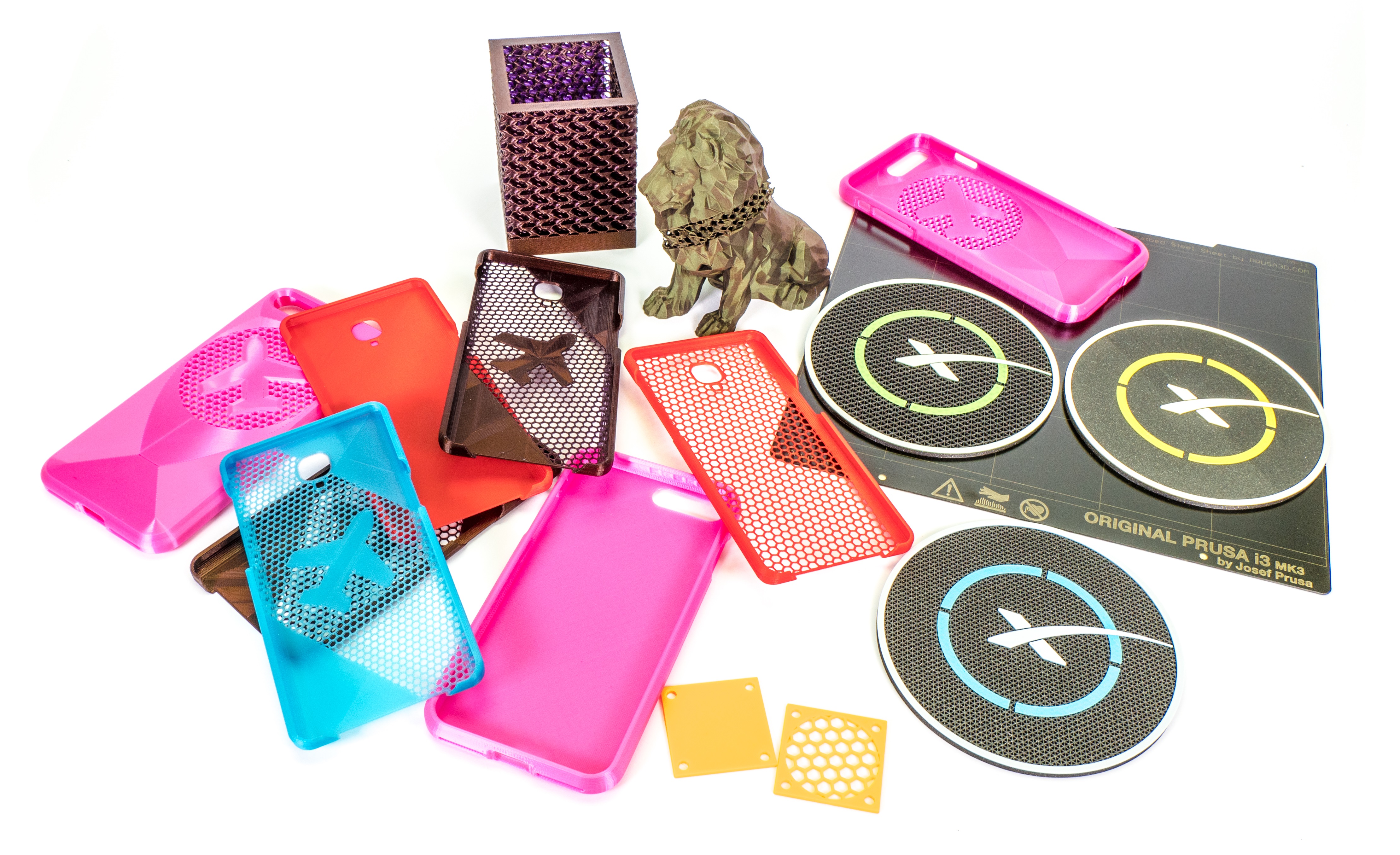 Modifier meshes
These are one of the advanced tools in PrusaSlicer and they’ve been there for a long time. Truth be told, working with them in previous versions wasn’t entirely user-friendly, so they haven’t been used frequently. Well, now it’s much easier to configure them exactly as you wish.
So what do modifier meshes do? They allow you to set custom settings and apply them only where the modifier mesh intersects the model. So you can set a denser infill, more perimeters or slow down the printing speed. You can either use simple geometrical shapes generated directly in PrusaSlicer or load an STL model that you created externally with another application. Let’s take a look at some examples.
SpaceX coaster – Zero number of top or bottom layers
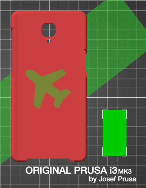
If you try to slice and print this SpaceX coaster, then most likely it ended up looking just like the yellow coaster in the diagram below. It looks good, but if we remove the top and bottom layers (the black part), we get this really cool effect!
Let’s open up PrusaSlicer 2.0 and configure to achieve this effect. First, download the model from PrusaPrinters.org. The print has three colors (Prusament PLA Prusa Galaxy Black, yellow/blue/green, white) and the filaments will be changed when the printer reaches a designated layer height. The bottom part of the model will be sliced with different print settings than the rest of the model. As a result, the bottom part will be without top and bottom layers.
- Import the model (spacex_single.stl) into PrusaSlicer. The easiest way is to drag and drop the STL file. Alternatively, you can click Add, in the top panel or use the keyboard shortcut Ctrl + I.
- On the Print Settings tab and in the Infill menu set the Fill density (recommended is 40 – 60%), then choose the Fill pattern (we recommend choosing Triangles).
- Go back to the Plater tab.
- Make sure you’re in the Expert mode. (Configuration -> Mode).
- Right-click on the model and select Add modifier -> Cylinder.
- Using the Scale tool (keyboard shortcut “S”) enlarge the cylinder and then move it (keyboard shortcut “M”) into such a position that only the bottom part of the model without the SpaceX logo will be covered.
- Then right-click the modifier mesh in the scene, choose Layers and perimeters. New settings are now displayed in the lower right corner. Set both Top and Bottom layers to zero, press Slice now and check the preview.
- Use the slider on the right side of the Preview mode window to specify, where the filament changes will occur. It should be approximately at 2.90 mm and 3.25mm – check the preview window to confirm whether you set the changes correctly.
- Export the G-code and print it! (You will be prompted to change the filament twice during printing.)
Print including modifier mesh changes is available as a .3mf file at PrusaPrinters.
Note: In the upcoming PrusaSlicer version 2.1, you will be able to make these changes based on layer heighhttps://www.prusaprinters.org/prints/88-spacex-landing-pad/filest, instead of using modifier meshes. Right-click the model and click Edit layers. Then you can set the two heights between which the custom settings will be applied. And from this point, it works exactly the same way, as if it were a modifier mesh. By the way, you can add multiple height intervals and each can change different settings.
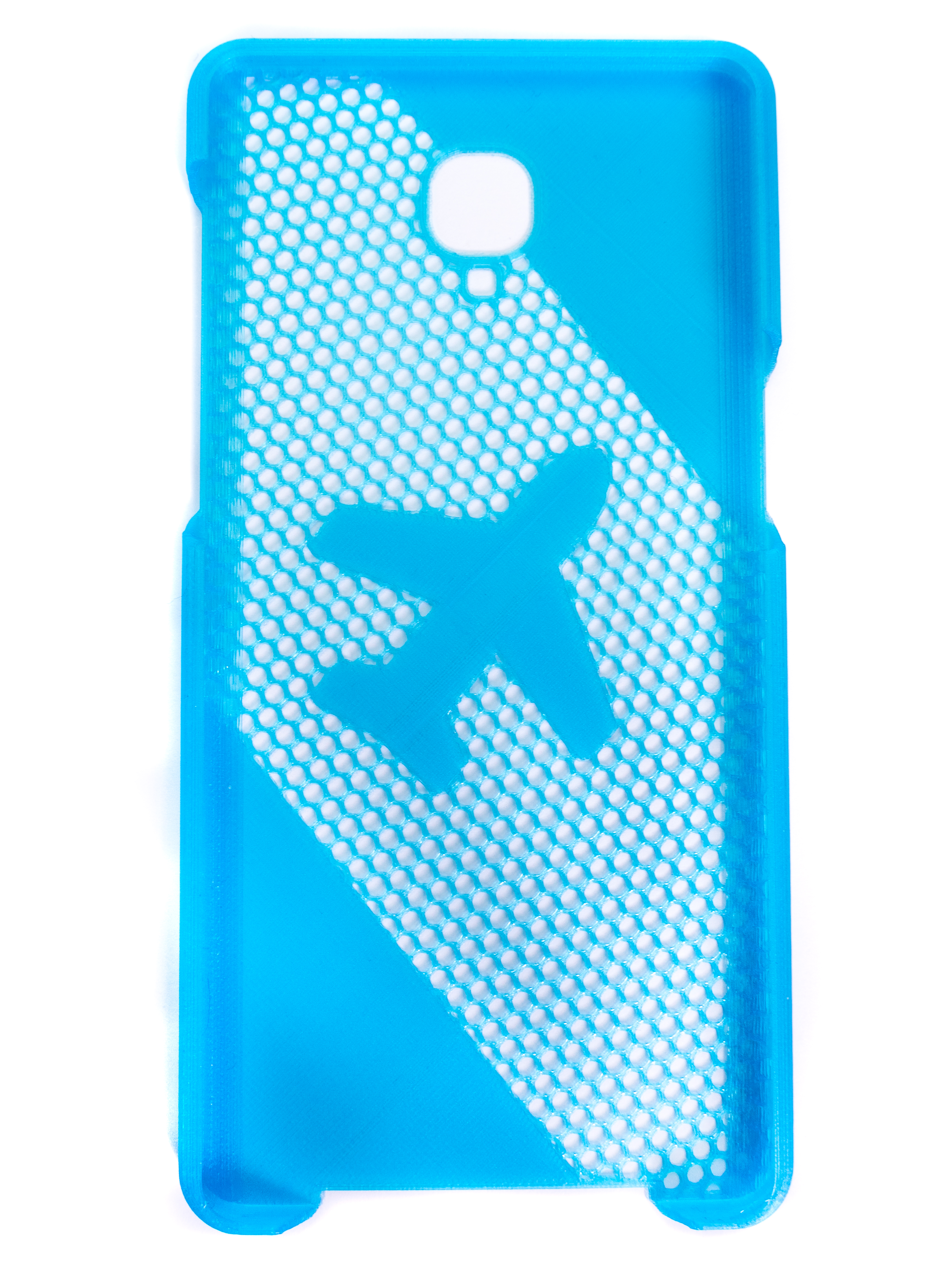
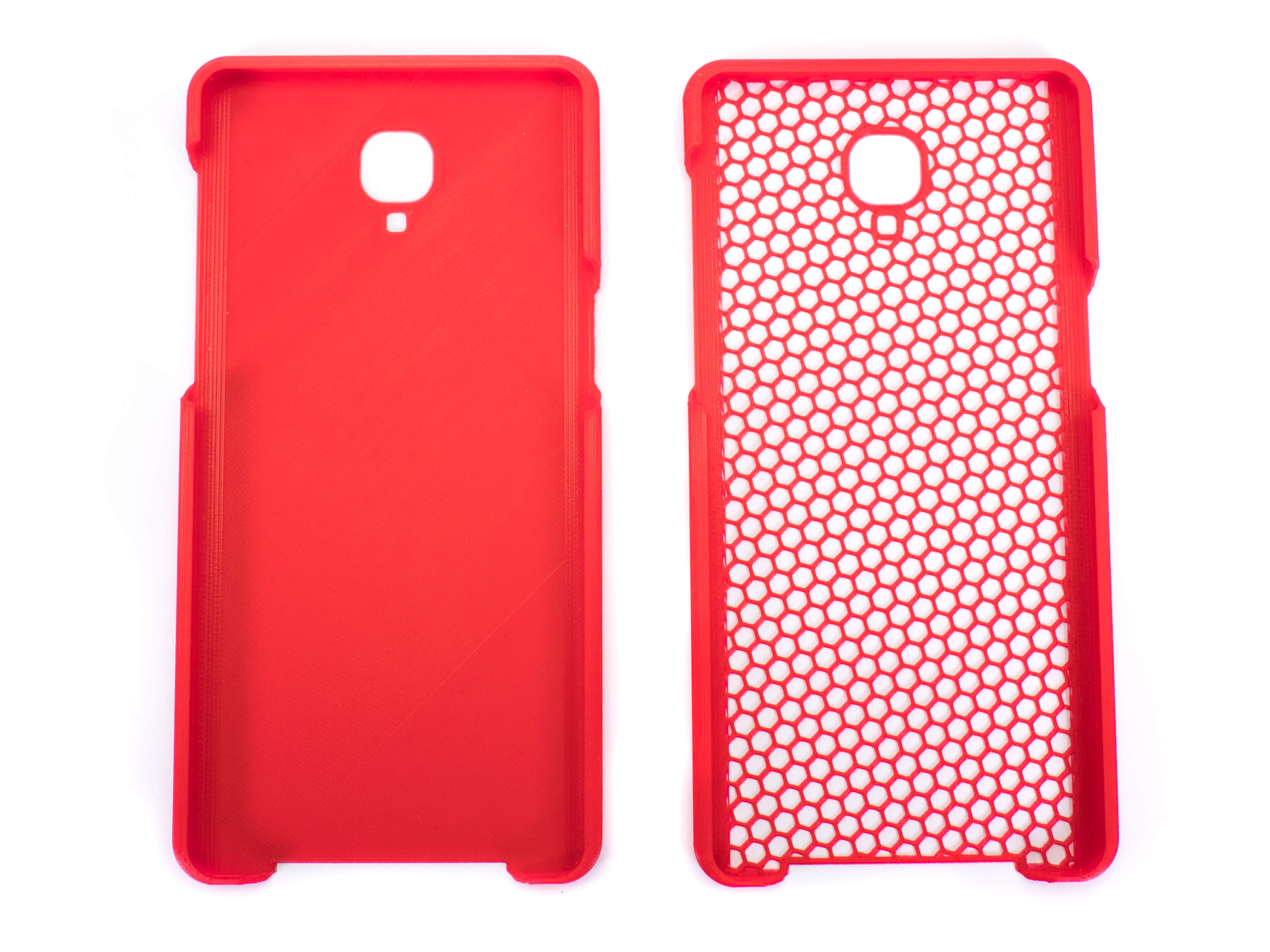
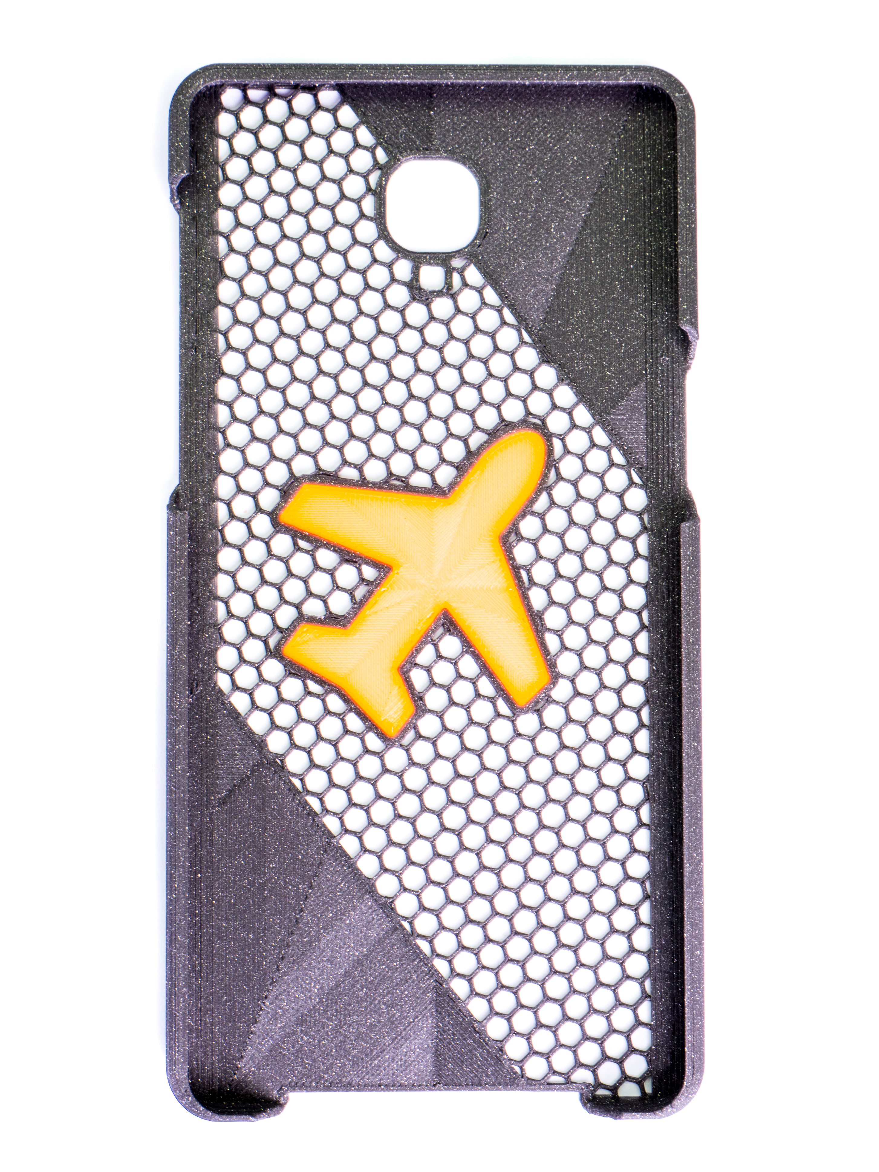
Phone Case – Custom modifier shape
Let’s take a step further and modify this phone case in a more interesting way. The trick here? We have used our own custom-shaped modifier mesh to turn the top and bottom layers off. Then, we loaded the second modifier mesh in the shape of a plane, which turns the hidden layers back on. For this example, we used a phone case model and an SVG plane image converted into a 3D STL model with TinkerCad.
And if you add the Multi-Material Upgrade 2S to your printer, you can even assign different extruders (colors) to the area that is being edited. So this is a really simple way to modify models for the MMU.

Don’t forget that you can also change the infill pattern for the top and bottom layers.
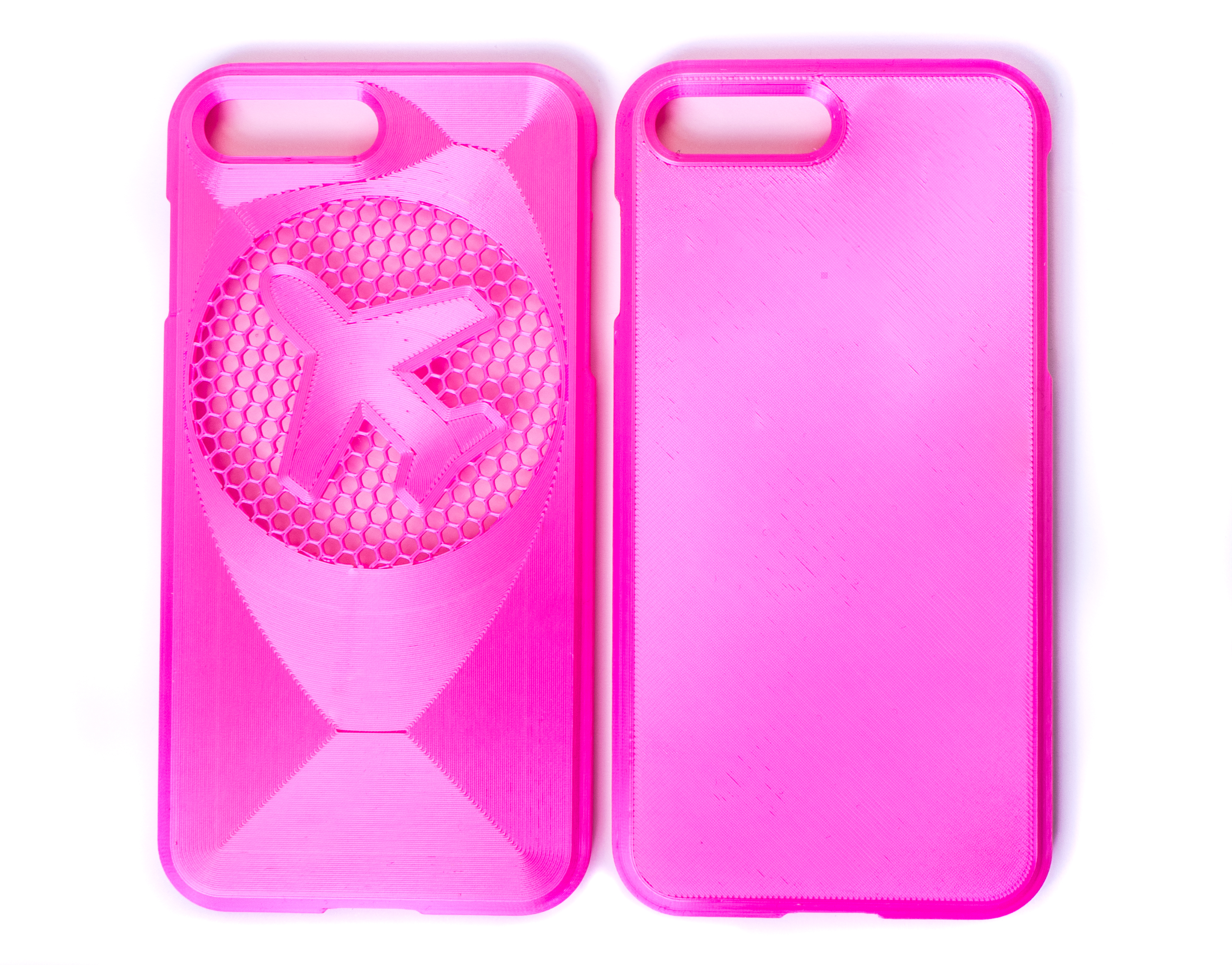
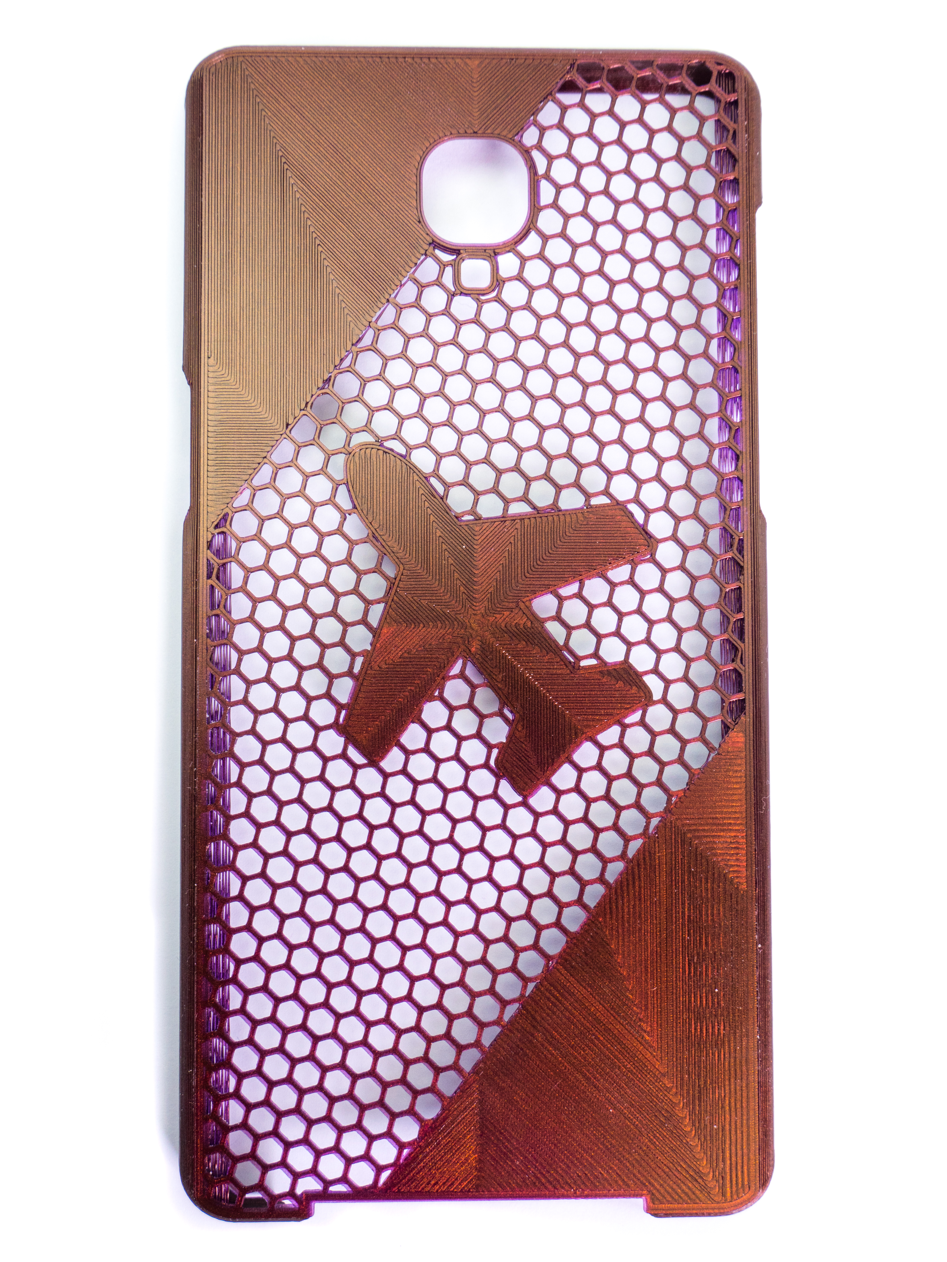
Two example models, including the modifier mesh changes, are available in .3mf file format at PrusaPrinters – iPhone 7 Plus, OnePlus 3T.
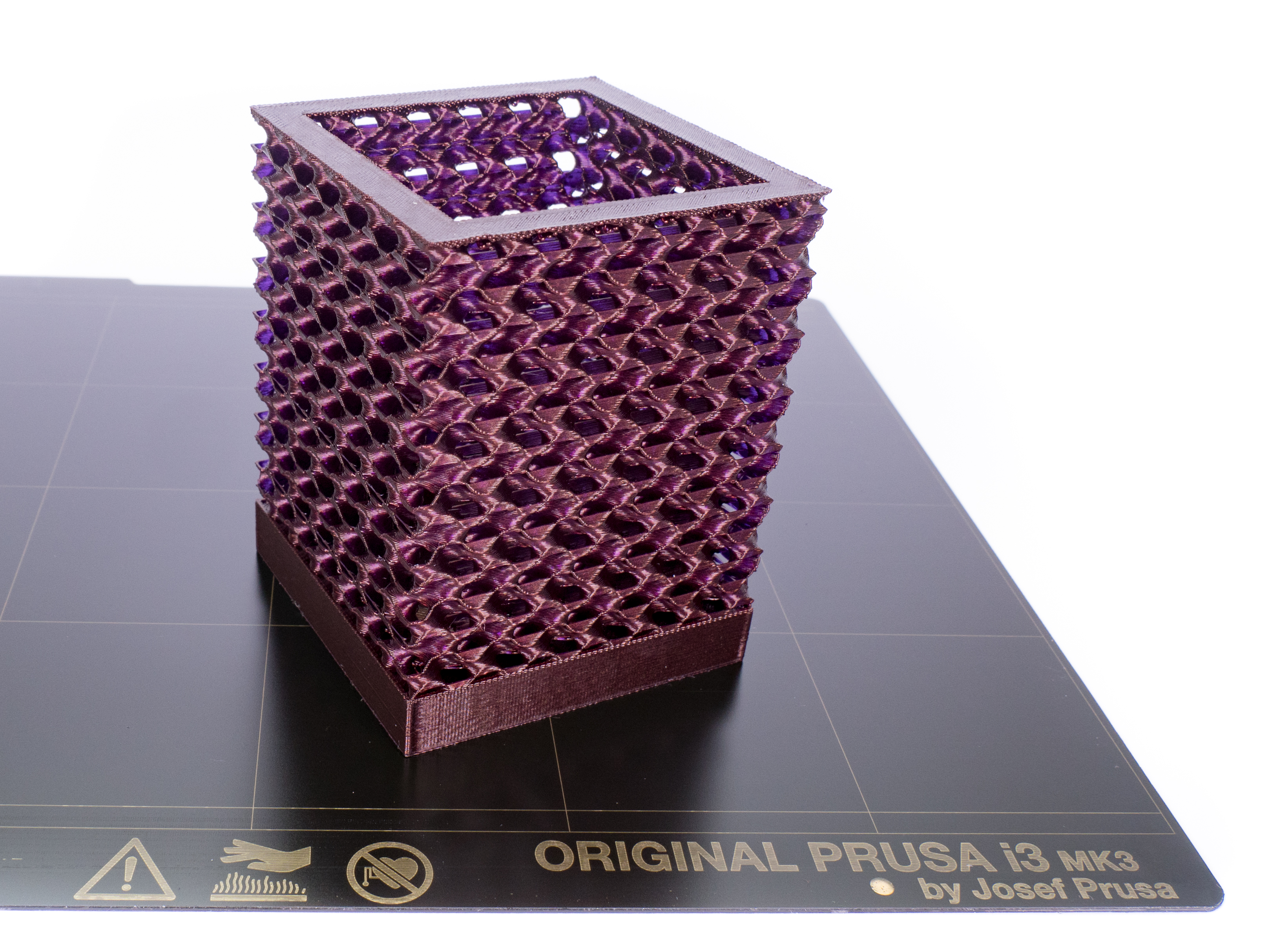
Pencil holder – Removing perimeters
Removing perimeters works pretty much the same way, but when using these, you should really consider applying 3D infills – like the gyroid or cubic infill. Compared to 2D infill patterns, 3D patterns look good not only from the top but also from sides.
Creating this pencil holder took just a few minutes. It’s literally just a cuboid minus the volume for the pencils. We have used a simple online modeling tool Tinkercad, but feel free to use your favorite 3D editor.
 3MF project file is available at PrusaPrinters.
In PrusaSlicer, use a modifier mesh to set the number of perimeters to zero. If you don’t turn off top layers, you’ll end up with solid layers on top. In our opinion, the result looks pretty good and creates a clean end for the infill, so let’s leave it like this. Consider adding a second modifier mesh just below the first one and set the infill to 100% with the rectilinear pattern. This way, there will be a few solid layers before the new infill begins.
Filament: Prusament Premium PLA Mystic Brown
And again, with version 2.1, you can achieve the same effect with the Edit layers function.
 Up until now, the changes we’ve made were focused on achieving a new look in existing objects. However, there are also practical applications. Let’s take a look.
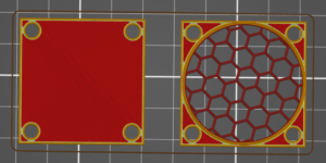
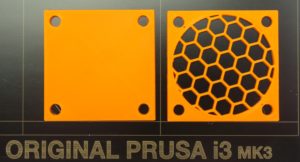
Fan cover – remove the top and bottom layers
Creating a fan cover is one of the practical examples. Just model a simple square-plane object with four screw holes – that’s it. That great-looking honeycomb pattern you see in the pictures below? Completely made in PrusaSlicer! Import the model in PrusaSlicer and add a cylinder shape modifier with the following parameters: 15% infill, 0 top, and bottom layers, 2 perimeters. Sure, if you have good 3D modeling skills, this would be a no-brainer for you. On the other hand, this is a good solution for beginners – it’s quick, easy and also pretty original 🙂
Local strengthening of the model

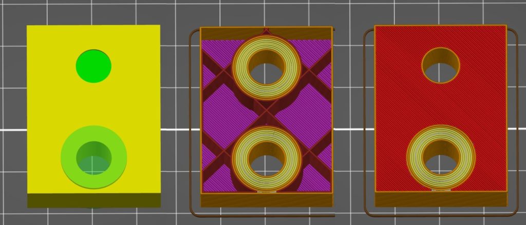
Modifiers are useful when you need to make a part of a model stronger – e.g. a part that should go under a screw. Of course, it is possible to make stronger the entire model by adding perimeters or adding infill. But this will mean longer printing time and higher material consumption. It is usually sufficient to make the model stronger in the area where it will be stressed the most. If you want to keep the bottom and top layers intact, place the modifier just between the top and bottom layers (it’s the top hole in the example below). If the modifier mesh intersects the surface, the circular pattern will be visible on the object (bottom hole in the example below).
Create a hole in the model
Although slicer is not designed for modeling, in some cases we can perform simple operations with it. With modifiers, we can make a Boolean difference using a model and a modifier object. To do this, add a modifier and set the parameters to following values: 0% infill, top and bottom layers to 0, and the number of perimeters to a non-zero value. As a result, we don’t need any other modeling tool to achieve this goal.
Modifiers can also be rotated around all axes in the coordinate system – same applies to models. This may be interesting and useful in some cases.
Conclusion
Now you know how PrusaSlicer can be used for simple model modifications. Modifier meshes are an incredibly powerful tool and you can also use them to improve the mechanical properties of your prints, or greatly reduce the print time. You do not need any other modeling tool for the editing examples mentioned in this text. Modeling a Gyroid infill wouldn’t be certainly easy. On the other hand, we are limited by predefined infill patterns and not all parameters can be changed. This means, for example, that you cannot choose the number of perimeters that create the infill – the Honeycomb pattern will always have two perimeters. So it has certain limits, but due to its simplicity, it is certainly worth a try!
Happy printing!
Community prints
Have you already tried experimenting with modifier meshes? Don’t keep them for yourself! Share your prints and models at PrusaPrinters.org, in our forum, Twitter, Instagram or Pinterest and we’ll add your picture to the gallery below.
I found another creative use for modifier meshes while doing layout modeling in PrusaSlicer, creating slots/holes for sticks/dowels to use to reassemble a cut up model. See my forum message here:
https://forum.prusaprinters.org/forum/prusaslicer/feature-request-slice-peg-hole/#post-158311
I was quite brief but I think this would be an interesting topic to more thoroughly describe (possibly using a better suited model) for a blog entry.
Great tutorial and clear instructions as usual. That said, unfortunately the 3D infills ( 3D Honeycomb and Gyroid ) have a thin layer as caps partially covering the vertical faces. When these infills are exposed they look awesome but only from top and bottom ( as presented here ). If they are exposed from sides ( vertical faces ), their faces are partially covered with a thin liner. I had make a couple postings here and there on the subject. I wish there was a way to opt-out of that thin liner when we are using the exposed 3D infills for decorative purposes
Same here, I made a photo of the “ugly side” of the pen holder here: https://www.prusaprinters.org/prints/4337-gyroid-pen-holder/comments#comment-21324 no solution so far.
I’m having a difficult time when importing a custom shape to use as a modifier mesh. If I import it as just a shape to print, it imports fine, the scale is perfect. But if I import it as a modifier mesh, the scale is off, one axis is too big the others are too small.
Hi there,
I must also tell it is not working for me.
I was successfull making the fuzzy skin stuff but getting this one working turns out to be not working!!!
A locksmith will charge a flat rate for programming or unlocking a key fob. There are no additional fees for the technician to use his knowledge and expertise to unlock your car, let you in, or program the remote. You should know how much does a locksmith charge to program a key fob for best experience. The cost of programming a new key fob is based on how many keys are being programmed at once. If you have only one key and want to program it, the cost is $15. The same service will cost $25 if you need to program two keys at once.
Unfortunately this doesn’t work well with Pursaslicer 2.6.0 as it overlaps the infill with bridge infill, making it look horrible. There should be a setting for this, so we can turn it off.
<a href='https://mail.google.com'>Omaar bhai</a> Thanks Omaar bhai for helping us in our difficult time.