From time to time, every 3D printer owner is asked the same question: “Why is the printer really good and useful? I cannot imagine what would I use it for.” I did not find a satisfactory answer to this simple question at first, because I don’t consider printing figures and statues as the right example. That’s why every time the 3D printing technology is applied in practical use, I’m excited! Today, I’ll show you how to print a 3D map, that can serve in a number of situations not only using our Original Prusa i3 MK3 printer. How about a plastic model of terrain for school education, a small-scale version of a national park, a model that shows the overview of a real-world race track, or perhaps a tiny version of a mountain you climbed in the past. Thanks to these models, we can see the landscape from a bird’s eye view. Input data will be topographic maps that are most interesting for 3D printing purposes.
Models based on maps can be divided into two groups:
- Printing a terrain model – ideal for mountain ranges, volcanoes or abysses. So where there are well-known elevations.
- Printing a terrain model including buildings – ideal for cities and areas with buildings.
How to get a model?
Terrain models
A 3D terrain model (without buildings) can be obtained simply and for free with the Terrain2STL web application.
- Find a place on the map. Rugged terrain works the best.
- On the Location tab, press Center to View. This will show a selection rectangle on the map.
- On the Model Details tab, adjust the size of the selected area by moving the Box Size slider. The selection can be moved in the map. If the resulting model is very flat, it is possible to scale it on the Z axis. This is done in the Model Details by using the Vertical Scaling slider. However, keep in mind that the resulting model will differ from reality.
- On the Water and Base Settings tab, set the desired model base height.
- Press the Generate Model button. Then click the Download button and download the model.
Model Shape
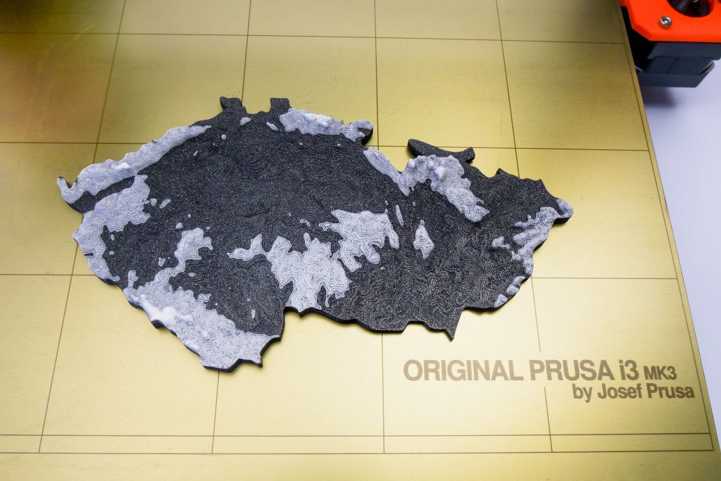
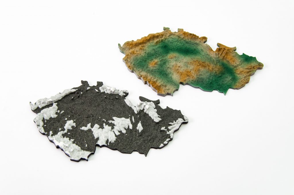
Does a square or rectangular shape feel way too ordinary? Let’s take a look at how to work with some more complex shapes. Naturally, one of the basic ideas is to use borders of existing countries. For the sample print, I chose the Czech Republic – the home of Prusa Research. A good start is to successfully obtain the STL terrain model from the previous step. However, the disadvantage of the Terrain2STL application is that it is not possible to change the shape of the selection. So, if you want to work with a larger area, you will need to cut the STL model first using a 3D editor and then work with it. This is because the Tinkercad software we want to use limits the size of the imported file to 25MB. A better solution is to use a similar tool like Terrain2STL. The TouchTerrain project allows you to select any aspect ratio on the map. I recommend aligning the map, for example, in the upper left corner for a simpler placement of the shape for the cutout.
How to do it:
- Find and download the desired shape in .SVG format. Ideally, it should be on a white or transparent background. To make searching easier, I recommend adding the keyword “silhouette“.
- In a web browser, open the Tinkercad tool and sign in (or create a free account).
- Create a new design by pressing the Create new design button.
- Create a block (use the “Box” tool on the right) and change the dimensions so it stretches across the entire Workplane.
- Import the downloaded .SVG file with the shape using the Import button in the top right corner. When the import is complete, the image is automatically converted to a 3D object. Change the shape type to “Hole“.
- Click the object with the right mouse button and first adjust its height in the Z-axis so that it is higher than the block. Then, adjust the size of the model by dragging any corner to fit the block. To keep the aspect ratio hold the Shift key.
- Now select both objects (Ctrl + A), group them with the Group button (Ctrl + G) and change to the “Hole” type. This creates a negative shape, which then cuts the terrain.
- Import the terrain model using the Import button in the top right corner and wait for it to finish.
- Adjust the size of the terrain model and place it in the right place in relation to the carved shape.
- Deselect the selection of objects by pressing the mouse outside the print area.
- Export the object using the Export button in the top right corner of the .STL format.
- The model is ready to be sliced, for example, in Slic3r, where it can be scaled in the Z-axis if needed for better terrain visualization.
Download link: The Czech Republic 3D terrain model on PrusaPrinters
City model with terrain
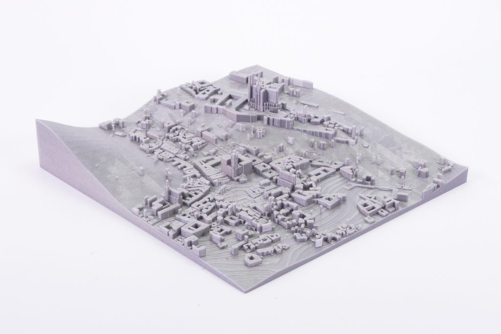
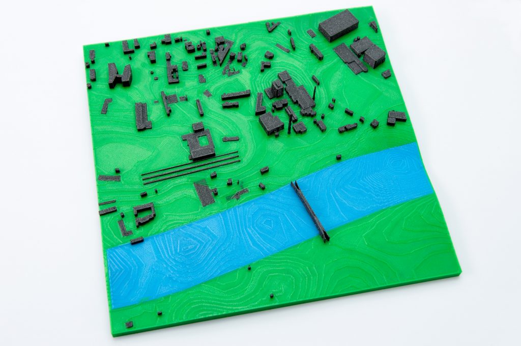
In this case, the procedure is a little more complex than the terrain itself and more tools need to be used. To get the model, we use the CADMAPPER web tool, which uses freely available maps from OpenStreetMap as a source. The tool allows you to download a 3D model up to 1 km² area for free. Larger areas are paid. In most cases, 1 km² is perfectly fine. By covering the entire print area (25 x 21 cm), we get the ideal scale for the model (approximately 1: 4000 to 1: 5000).
- Open CADMAPPER tool in the browser and click Create a map.
- Select the desired area up to 1 km² (or larger and buy the model).
- Select the output format for SketchUp 2015+.
- Include Topography and 3D Buildings in the output model and choose the height of buildings for which the height in the map is not defined.
- Press the Create button to start generating.
- Press the Download button to download a generated zip file that contains the .SKP file.
Prepare SketchUp and install Eneroth Terrain Volume extension
The downloaded file is not yet fully prepared for slicing. What we need to do is to create an object under the terrain. In addition, we can simply change the height of buildings in this tool, especially those that have a default value from CADMAPPER. We will use SketchUp Pro for editing, which is free to download in the trial version.
Eneroth Terrain Volume extension is useful when you want to create a solid object under the terrain easily. Download this extension as well.
Add extensions using the Window -> Extension Manager. Press the Install Extension button and select the downloaded file from the previous step.
Now we have everything ready and we can start editing the model.
- Run SketchUp, open the downloaded file from CADMAPPER (File -> Open).
- On the right side of the application window, expand the Layers section and remove all layers except buildings, topography and Layer0. Press the “Delete content” icon. The content of the deleted layers is not easily printable, that’s why we’re deleting them. However, you can play around with the content of deleted layers and see if something interesting comes out of it – we won’t be using them in our guide, though.
- Click anywhere on the terrain to select it. In the top menu of the app select Extensions menu -> Eneroth Terrain Volume. This creates a solid object under the terrain.
- If you want to change the height of the base or buildings, you must explode the model (select the whole model, right mouse button, Explode option), and then the Push / Pull tool to increase or decrease the height of the buildings or the base under the model.
- Export the model using File -> Export -> 3D Model.
The file is now ready for 3D printing. Open it in the Slic3r PE and adjust the size to fit the print area. For an area of 1 km², the approximately square shape of the model is reduced to about 20% of the original size. So we get the model on a scale of cca 1: 5000. We recommend a PLA material and a layer height 0.15mm.
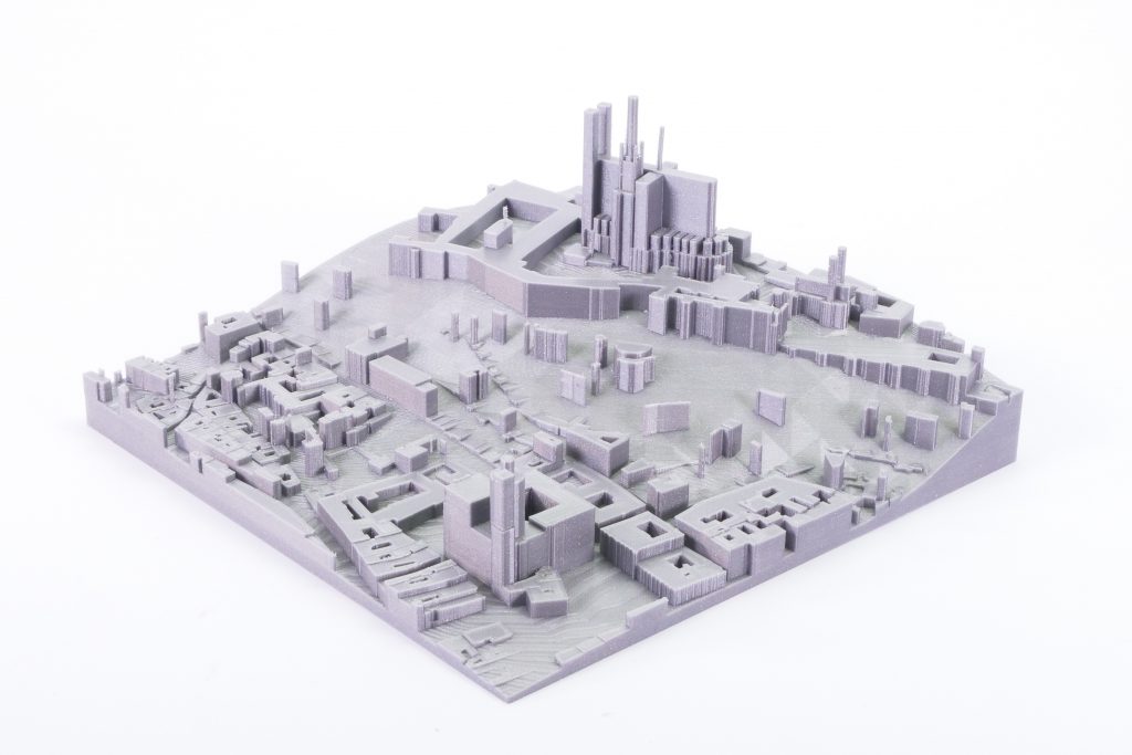
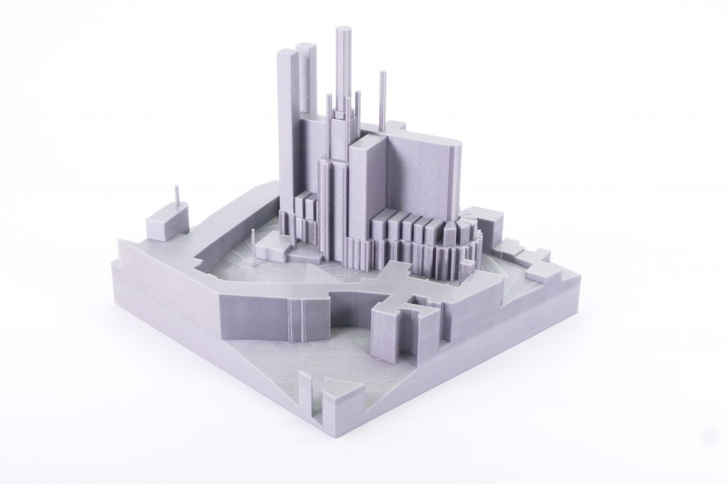
Download link: Prague Castle area on PrusaPrinters
Preparing the model for printing and correct orientation
Use Slic3r PE or your favorite slicer tool to generate the gcode file.
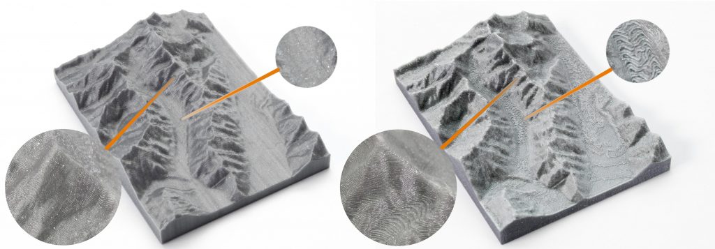
Terrain models with at least one straight edge can be printed in two ways, either horizontally or vertically. Each of these orientations has its pros and cons and for each model, it is necessary to decide which orientation to choose. Let’s look at the main differences.
The horizontal position
This position is natural in the real world. In this position, we are able to print almost any model. In the Z-axis, however, we are limited by the height of the layer. The lowest height of the extruded material is about 0.05mm and the most commonly used nozzle diameter is 0.4mm. The relatively large diameter of the nozzle alone causes “drops” on the peaks. The nozzle diameter also affects edge sharpness.
We recommend selecting a layer height of 0.15mm and a 15% to 20% infill.
Pros:
- you can print almost any model
- there are horizontal lines on the model that represent contour lines (some may consider this a con)
Cons:
- infill is necessary (longer printing time)
- drops on peaks
- there may be strings between the peaks/buildings
The vertical position
In the vertical position, the biggest advantage is that no “drops” of material on the peaks will be created, and the peaks will be smoother. This makes the surface more detailed and looks much better. The vertical orientation is suitable for models where there are no areas that make an angle with the print area less than about 45°. Supports for such models is not a solution we would recommend.
Vertical orientation is also not suitable for printing city-building models, because almost every building would have a perimeter wall parallel to the print surface and therefore the model would be non-printable without supports.
With vertical orientation, it is advisable to choose the most suitable area on which the model will be placed. Choose the one that will touch the bed with the largest possible area. Use the Place on the face button to rotate the model.
We recommend selecting a layer height of 0.15mm and a 0% infill. Infill is not needed in most cases. The printing time will be almost half and you save some material. For best results, use PLA filament.
Pros:
- print without support and infill
- there is no stringing between peaks
- the terrain looks smoother than the horizontal print position
Cons:
- can not be used to print city models
- there’s a chance that it will become loose and that the print will fail
The difference of print in horizontal and vertical orientation is shown in the pictures below.
Our tips for color models:
- Use ColorPrint to change the color of the filament depending on the altitude. Learn how to use ColorPrint in this article.
- Print the model with a single filament and paint it afterward. It depends only on your imagination.
- If you already have Original Prusa Multi Material Upgrade 2.0, you can try to create a color model to distinguish terrain, buildings, waterways and roads.
Feel free to experiment, try various changes and edits, and don’t forget to share the results in our forum.


Could the same or similar technique be used to print, say, medieval ivory carvings? I would need, I think, a way to substitute a picture of a carving for the map in your article. Any ideas on how that might be done?
Hello Ken,
I did that by using the Microsoft 3d Builder´s import feature.
For my requirement it did a great Job.
really great article ….so informative…thanks
Really helpful articul, I have just one question. What retraction setting you recommend when printing buildings and cities?
Great article, one question. What retraction settings would you suggest?
I would like to thank you for the Great article, but I have a question, where can I search for a .svg file format, to provide a download address please, thank you
Hi, when I try to build volume in SketchUP by using: Extensions menu -> Eneroth Terrain Volume. It did nothing. I tried to choose one object or all map but it didnt help me. Do you where can be the problem? Thanks
Thanks for the article. I was given a model (.obj) with terrain and buildings, extracted from a GIS system called CityEngine. It had no base, no sides, and some top-layer gaps in the terrain. I found that I could use Microsoft 3D Builder to make it printable, using Edit -> Extract down to solve all of the above issues.
printing maps, terrains and landscape in 3D printing is much needed for travelers especially because it gives a clear view of any places in a map. in geographical purpose, it has a massive use.
www.facebook.com
I’ve been trying to get a couple of 3d townscapes printed through an agency. In both cases the agency identifies issues with non-manifold edges, boundary edges and intersecting faces. The problem seems to be the junction between the building and the base, and between the pitched roofs and the buildings (which are flat-topped 3d solids). Nevertheless my first model printed almost perfectly. My second one is on a stepped and landscaped base and has too many issues. Do you have any suggestions?
Cool
I would like to 3D print a model of a golf hole to show the end result of a proposed renovation. The problam is I only have a hand drawn topographical map of the planned layout. What is the best way to create a 3D printiable file in this situation?
is it possible to also include the roads in the exported STL ?
Is there a way to create the city scape with either SketchUp web, or Fusion 360?
The world of technology is developing every day and I really like to watch this development, I have no doubt that this is a very relevant topic for many, and that I am not the only one who likes to follow the world of technology. I want to recommend an excellent application called The Helios https://apps.apple.com/us/app/the-helios/id1602056819 . This application will help you choose the ideal lighting temperature for the room, and it’s very cool.
Is this up to date? I’m trying to follow the instructions directly but keep getting the error that the selection must contain exactly one group or component when trying to use the terrain volume.
The education is necessary because through this you become an expert and get acknowledge about different important aspects. Education software will help children and elders to teach themselves reading, writing and arithmetic skills. https://www.dumpsjournal.com/Exam/HPE0-V27-dumps.html provides authentic IT Certification exams preparation material guaranteed to make you pass in the first attempt.
2023 update about Sketchup: It’s not called Layers anymore, the layers are under “Tags” if you want to find them
A tip if you want to print landscapes in the vertical position: For bigger prints, this position becomes unstable. However, using the current (v2.6) version of Prusa Slicer, you can use organic supports to keep the print upright. If you tilt the model by a small angle (10 deg) from the vertical and use paint on support to draw some contact points at the model, organic supports will form parallel “towers” to the model and support it at the selected points, ensuring stability of the print!
It seems like the Eneroth Terrain Volume tool is not usable with the free online version of Sketchup, and it doesn't seem like you can get a local version of Sketchup for free anymore either (not including a short term trial). Is there an alternative way to do the the terrain step?
I can’t find tags in sketchup 2023 to remove unnecessary layers
Another great resource for 3D terrain maps:
https://contourmap.app/
It's in DXF format but you can convert it to another format