The Original Prusa I3 MK2 model introduced a handful of improvements over the I3 printer, most notably the full mesh bed auto leveling, zone heated print bed with a PEI print surface, and the integrated leadscrew Z axis. The full mesh bed auto leveling relies on an induction sensor mounted onto the print head, sensing its distance towards nine circular induction targets arranged on the new zone-heated print bed in a 3×3 regular grid pattern.
While the automatic bed calibration makes the first layer print hassle free, it requires the new MK2 printer to be assembled with a higher accuracy than the previous I3 model. Even a sloppily built Original Prusa I3 MK1 printer prints the ubiquitous tree frogs wonderfully. However, as many builders have experienced, the Original Prusa I3 MK2 is less forgiving. An imprecisely built MK2 printer will not hit the nine induction sensor points of the heated print bed close to their centers, leading to an uneven first layer thickness if one is lucky. With a bit less luck, one ends up with a print head crashing into the print bed and tearing the PEI foil.
At Prusa Research, we decided to remove some of the burden from the shoulders of the builder by our novel auto calibration firmware features. First we thought of letting the user shift the induction sensor to the centers of the induction targets manually using the printer front panel. Then the idea hit us. We could use the induction sensor to find the induction sensor target points on the print bed automatically. This translates to no more crashes of the nozzle into the print bed and no more teared PEI foil.
Today, even a not quite precisely built Original Prusa I3 MK2 printer will home and print correctly with the new 3.0.6 firmware after 10 minutes of an automatic printer calibration process. The calibration procedure finds the induction sensor points and it uses this information later for the skew correction. And we can correct even skewed Y/X axes!
This calibration process isn’t almighty. By design, it can’t compensate loose belt pulleys, if the printbed isn’t properly secured and wobble or if your nozzle deflects the bed during the process.
However when these basic requirements are met, XYZ calibration procedure achieves an accuracy of cca. 0.2 degrees in the skew of the machine axes, which corresponds to a deviation of 0.5mm over the print bed width. An average 3D printer builder will not achieve such perpendicularity, we often see the skew to be 4 to 8 times higher. As long as the 3D printer does not wobble, the new firmware could correct even such extreme skew and print perfectly perpendicular objects.
I think this is really amazing as we’re the first printer ever that could do this.
You can see the calibration process in our guide for a new user. Please note that the calibration was called Calibrate X/Y in FW 3.0.5 and was later renamed Calibrate XYZ in 3.0.6.
How we do it?
With the induction target points correctly located on the print bed, the mesh bed auto leveling will work even on a not quite precisely built machine. The tree frogs will print nicely, however chances are, that mechanical parts will not fit. Indeed, if the X/Y axes are skewed, the boxes will not be rectangular. The solution is on hand: Once the automatic calibration finds the 9 induction target points on the print bed, the firmware knows the actual machine geometry, namely the skew of the X/Y axes. And if it knows the skew, it could correct for it and the boxes will be perfectly square again!
Before the introduction of the automatic XYZ calibration, a print bed damage was not uncommon if the printer was not built quite accurately. Our novel XYZ auto calibration routine works hard to avoid the print bed damage caused by the initial induction target point misalignment. Even after the XYZ calibration procedure has been applied successfully, there is still a chance, that the induction sensor targets get misaligned over time, if any of the mechanical parts (nuts, nylon zip ties, the induction sensor itself) loosen, or the cable from the induction sensor breaks.
To improve the printer reliability and avoid the nozzle crashing into the print bed, we integrated a simple check into the 3.0.6 firmware. At the end of the XYZ calibration, the height of the induction sensor over each of the 9 induction sensor target points on the print bed are stored into a non-volatile memory as a reference. The next time the print performs the bed leveling, the newly measured Z values are compared against the reference Z values and if they differ more than 0.5 mm, the bed calibration is halted at the induction sensor point diverging from the reference height. This way the printer damage is minimized if something goes wrong with the printer, or if the user runs a bed leveling procedure with a cold nozzle covered by plastic scraps.
The XYZ Calibration Algorithm
The automatic XYZ calibration procedure proceeds in the following steps:
- An approximate skew of the printer axes and the print bed offset are calculated from the positions of four points only.
- Positions of all 9 points are measured and the shift and skew accuracy is improved.
- Z offset of the induction sensor is measured over the 9 induction sensor points and stored into a non-volatile memory as a reference.
The steps 1) and 2) are separated for performance reasons. To measure the center of an induction sensor target point, one needs to lower the Z axis to an optimal position (see Figure 2). If a printer was built accurately, the induction sensor will home in the region A (see Figure 1), and the optimal height for the X/Y calibration is reached by lowering the Z axis slightly below the point of the first trigger of the induction sensor. In case the induction sensor homed into the region B, the nozzle would not crash into the print bed yet, but the induction sensor would already be below the optimal Z height for the X/Y calibration. In case the induction sensor homed into the region C, the print head would or would not crash into the print bed, depending on the sensitivity of the particular induction sensor.
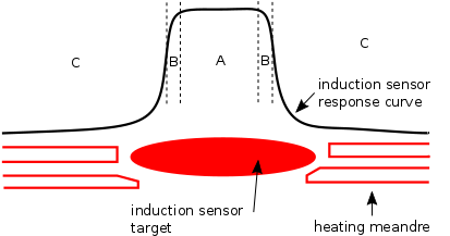
Figure 1: Valid (A), invalid (B) and dangerous (C) regions for induction sensor homing
Therefore to avoid the nozzle crashing into the print bed during the first step of the XYZ calibration procedure, the induction sensor is lowered slowly while moving the print head in a zig-zag movement around the expected position of an induction sensor target point, until the induction sensor triggers. Likely the X/Y/Z position where the sensor triggers first will be at the tip of the induction sensor response (see Figures 1, 2). Because this kind of search is very slow, only four points are searched for in the first step: front center, right center, rear center and left center, which are sufficient to establish the initial estimate of the machine geometry. The choice of the four points, over which this time expensive zig-zag search is performed, is not arbitrary: There are metal screws near the corners of the print bed, which could produce spurious responses of the induction sensor, therefore these target points are ruled out from the first step of the X/Y calibration.
In the second step of the XYZ calibration, the initial estimate of the machine geometry calculated from the four points measured in the first step is used to target the region A (see Figure 1) at all the nine induction sensor points, where the position of the target points is finalized by the algorithms described in the section Induction Sensing and later processed by the Gauss-Newton non-linear Least Squares fitting described in the section Data Processing
In the third step Z offset of the induction sensor is measured over the 9 induction sensor points and stored into a non-volatile memory as a reference. This allows us to prevent accidental damage to the print surface if something become loose or even break.
Theory
Induction sensing
The Original Prusa I3 MK2 printer applies a tiny inductive proximity sensor to measure height of a print nozzle over a print bed at 9 regularly spaced points. An inductive proximity sensor emits an electromagnetic field, which interacts with close metal bodies by inducing eddy currents in them. As the eddy currents in the close metal bodies increase, the amplitude of the electromagnetic field emitted by the induction sensor decreases. Once the decrease of the emitted electromagnetic field reaches a certain threshold, the sensor triggers.
The sensitivity of the inductive proximity sensor depends on multiple factors. Tiny sensors are less sensitive than the large ones and the size, conductivity and continuity of the induction target is important as well. A large thick solid metal sheet is an ideal target, but a heated metal sheet is quite an expensive proposition. The MK2 print bed is an evolution of the PCB heat bed, which has been introduced to the 3D printing community by Josef Prusa. The PCB print bed is covered by a heating meander, which is a bad induction target on its own. While the copper traces on the PCB print bed are conductive, the traces do not form a continuous surface, therefore large eddy currents cannot develop and the sensitivity of the induction sensor is compromised. To increase the induction sensor sensitivity to the PCB heated print bed, the MK2 print bed is augmented with nine solid copper circular points of 8 mm diameter.
The dimensions of the induction target points are a result of an optimization. Too large induction points lead to cold spots on the heat bed, too small induction points do not provide reliable response to the inductive proximity sensor. To avoid cold spots, the induction sensor points are small, therefore they have to be homed by the induction sensor quite accurately. For the induction sensor to hit the target point accurately, either the printer has to be built quite precisely, or an automatic calibration procedure is called for.
The inductive proximity sensor is an eye to the printer. Although it is really just a glorified contactless on/off switch, we could trick it into measuring positions and distances in the X/Y plane. Namely, we hope to measure the centers of the induction sensor target points with a sub millimeter accuracy. When reaching the induction target center from the top (see Figure 2), the accuracy and repeatability of the height measurement is very good. The induction sensor is less precise in the X/Y plane though. First, the induction sensor is noisy. Second, the induction sensor response curve is influenced by nearby conductive objects, namely the heating meandre and the metal screws fixing the heat bed to the print table.
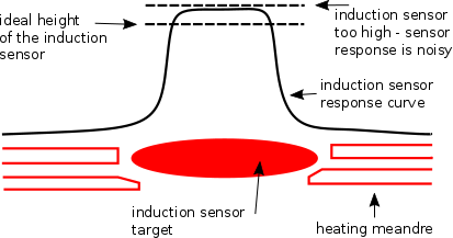
Figure 2: Response of an inductive proximity sensor over a print bed target point
Figure 2 visualizes the response curve of an inductive proximity sensor over one of the MK2 print bed sensor target points. The induction sensor triggers highest over the center of the target point, it triggers lower at the sides of the induction sensor response curve. Away from the induction sensor target point, the proximity sensor triggers against the heating meandre. Depending on the sensitivity of the particular induction sensor, the sensor may not trigger at all when homing far away from the induction sensor target point, crashing the print bed by the nozzle.

When the induction sensor moves along the flat top of a response curve (see Figure 2, top dashed line), a slight noise may lead to a large jitter in the XY position, where the induction sensor triggers first. To get a reliable XY sensor response, one has to lower the sensor a bit, so the noise shots themselves do not lead to spurious sensor responses. One has to be careful though to not lower the sensor too much, as that would bring the nozzle to a collision with the print bed.
We verified a fairly accurate method to calculate the center of an induction target point: Lower the sensor to the ideal height (see Figure 2) and find the first hit when moving from left to right, then right to left. Averaging these two hit points gives an estimate of the X coordinate of the induction sensor target point. Repeat the same procedure for the Y coordinate. After a couple of cycles, the estimated center point aligns with the real center with a reasonable accuracy. Now the accuracy of the center may be improved by averaging the X/Y positions over multiple such cycles.
The aforementioned method works for induction targets, which are accessible by the sensor from all four directions. Unfortunately, this is not the case for the first row of the induction target points on the MK2 print bed, which are too far in the minus Y direction. Therefore the front “no trigger” position cannot be reached mechanically and the Y center has to be approximated by other means than as an average of the front and rear trigger coordinate. One possibility is to search for a maximum width between the left / right hits when moving slowly along the Y axis. This works to some extent, but due to the noise of the induction sensor the maximum width Y coordinate is not very accurate. An alternate solution is to measure a handful of hit points (for example going from left to right, right to left and back to front), and interpolate a circle through these points. In case the printer has been built in such a way that the center of a front row induction sensor point is already at the edge of the printer working space or not even reachable mechanically, the circle interpolation method is the only choice left.
Data Processing
Having measured the positions of the nine induction sensor target points, one may just use these positions during the bed leveling procedure directly to position the induction sensor. One may do better though if one makes use of the fact, that the data set measured is highly redundant. Let’s assume, that the X/Y belts and pulleys are accurate, so the distances traveled along the X and Y axes of the printer are correct. Then the deviation of a geometry of a user built machine from a perfectly built machine may be described by a skew of the X and Y axes, and by the shift of the print bed. The goal is to fit the positions of the 9 measured calibration points to 9 model calibration points. The set of 9 pairs of 2D coordinates generates 18 degrees of freedom. By reducing the 18 degrees of freedom to just 4, the accuracy of the calibration procedure is greatly improved.
Finding the skew of the machine axes is a bit involved, though the tools of the trade are three hundred years old. Usually the measured data are fitted to a model while minimizing some error metrics. A method called Linear Least Squares Fitting, which was first described by Carl Friedrich Gauss in 1795, minimizes a sum of squared differences between the target points and the measured points transformed by some linear system. The Linear Least Squares method is very popular due to the low computational demands: Only a single linear system of the size 6×6 needs to be solved to find the shift of the print table, the skew of the machine axes and the scaling of the machine axes. But allowing the fitting procedure to scale the axes is a dangerous proposition. It may or may not do the right thing. If the input data is noisy, it is safer to prohibit the stretching and shrinking of the machine axes by the model. If no scaling of the machine axes is allowed, a more involved non-linear Least Squares Fitting has to be performed, which cannot be solved directly, but only iteratively. In the Prusa3D 3.0.6 firmware we implemented the Gauss-Newton non-linear fitting procedure.
… and that’s enough theory for today, you can take a look at our FW over at PRUSA3D Github or in the article on PrusaPrinters.org with summary of changes. 🙂
Vojtěch Bubník, Prusa Research FW guru
Very much informative, thank you and your team for the good work!
Agree with that
It is a great machine,I hope I will be able to afford one soon
Helpful Post! Thank you for sharing this effective information about the first printer to automatically correct its geometry in all axes. I have been using the Prusa I3 MK2 printer for the last six months. So I have learned some good information about machine geometry calculations and how it’s important. Recently I have also learned about it from this mathematical discussion forum here- where you get many mathematical questions with answers that can help to learn many math equations and formulas. appreciated the author for this tutorial.
Good share. Thanks https://blog.prusa3d.com/
please bring back X Y Z correction in MK4 !!!