


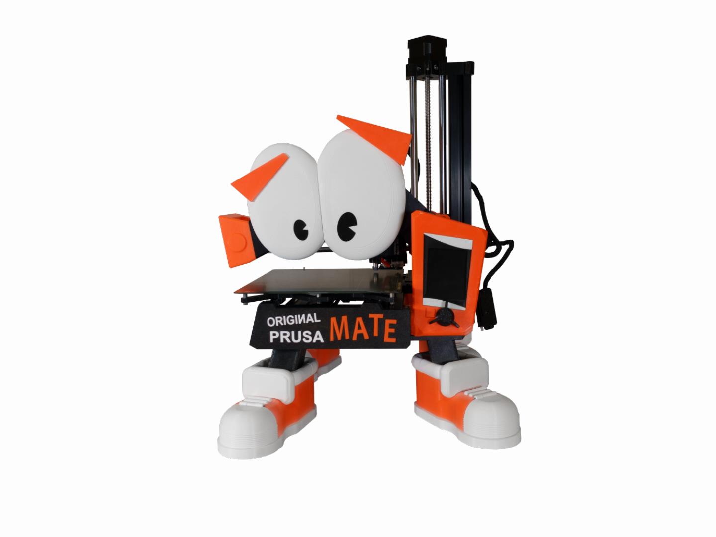
We see lots of Prusa inspired creations uploaded to Printables, but from the first time we saw Neil3dprints’s PrusaMates, we fell in love with these quirky little characters inspired by our printers. In fact, the first PrusaPrinters Pick of the Week on PrusaLive was Neil’s MK3 PrusaMate. The idea started to be whispered about, “Could Neil make a real printer look like one of his creations?” Well, we are happy to share with you today the answer to that very question by presenting the Original PrusaMate MINI Mod. What follows are Neil’s introduction and his instructions on building this incredible modification to our Original Prusa MINI.
Neil is a Printables community member known best for his PrusaMates, Little City models, and the Print A Toons. You can support his work through his Patreon. If you would like to learn more about Neil, check out our 2020 holiday special of PrusaLive to see our interview with him.
When I designed the very first Prusa Mate it just looked completely….. wrong, but I loved it.
It was adorable, bonkers, silly, and quirky all at the same time. And just by staring at its startled face, it was making me smile and laugh.
So, when the Prusa team reached out about a collaboration, I eagerly said ‘I want to make a Prusa Mini look like a cartoon.’
Now I knew the challenges. What I wanted to attempt was to turn a practical workhorse of an engineering marvel and make it look like a toy. The trick though was keeping the practicality and engineering qualities of the printer. I wanted people to initially look at it and question if it still prints or if it were an actual printer at all. I wanted it to be something children would want to use or ask questions about. To encourage the next generation of potential 3d printing enthusiasts to stop and take note of this quirky printer.
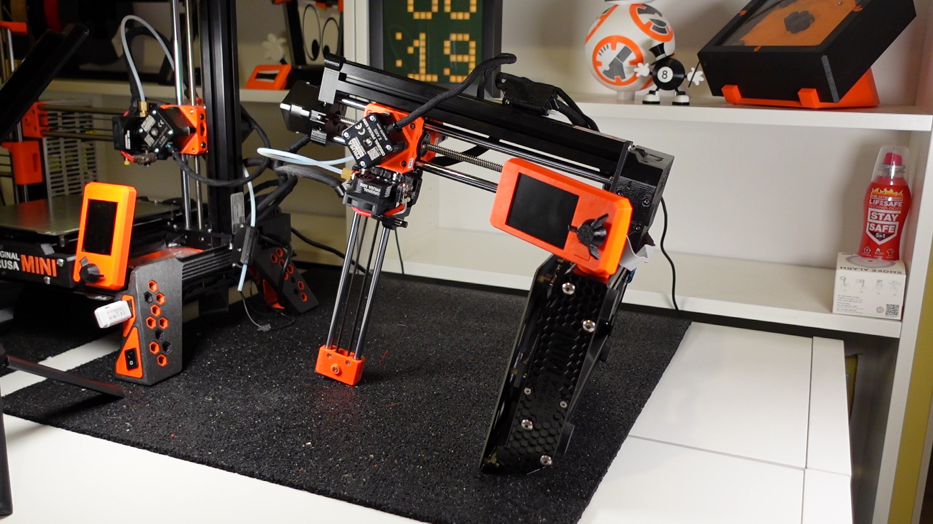
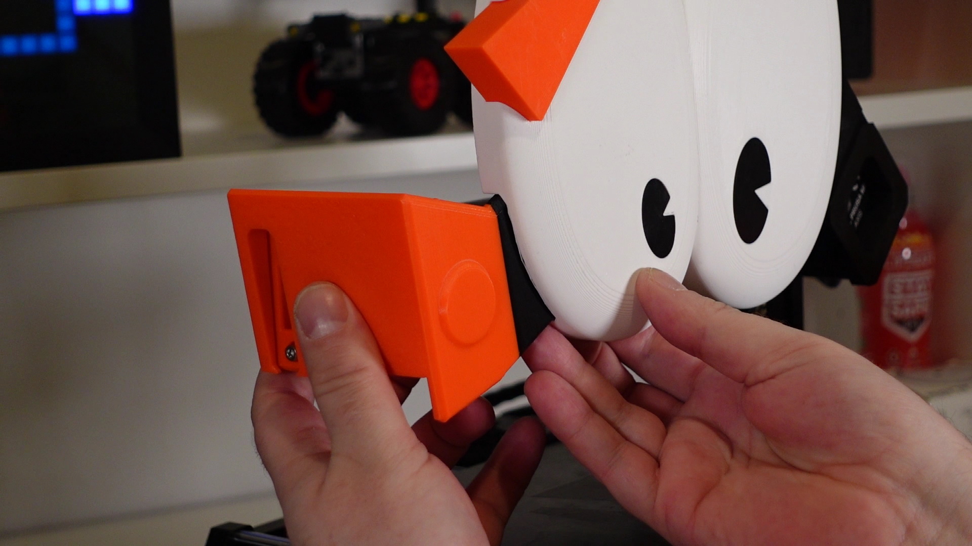
So, after many months, test prints, redesigns, I give you the ‘The Original Prusa Mate add-on.’
The ‘Prusa Mate’ add-on is a fairly simple addition to any Prusa Mini.
The STL’s are available to download on Printables.com. There is even a Step file for the entire model in case anyone would like to make some amendments or changes to any of the parts.
Relocating the on/off switch and USB slot to the front of the printer are optional steps. If you decide to move the on/off switch and USB slot to the front of the printer, then the below additional parts will be required. There are links to some of these so you can see which ones I used.
You’ll need to print the front shoe parts with ‘version 1’ in the file names. Some of you may decide not to touch the wiring side of this project, in which case the optional parts will not be necessary, and you’ll just need to print the front shoe parts with ‘Version 2’ in the file names instead.
Optional parts:
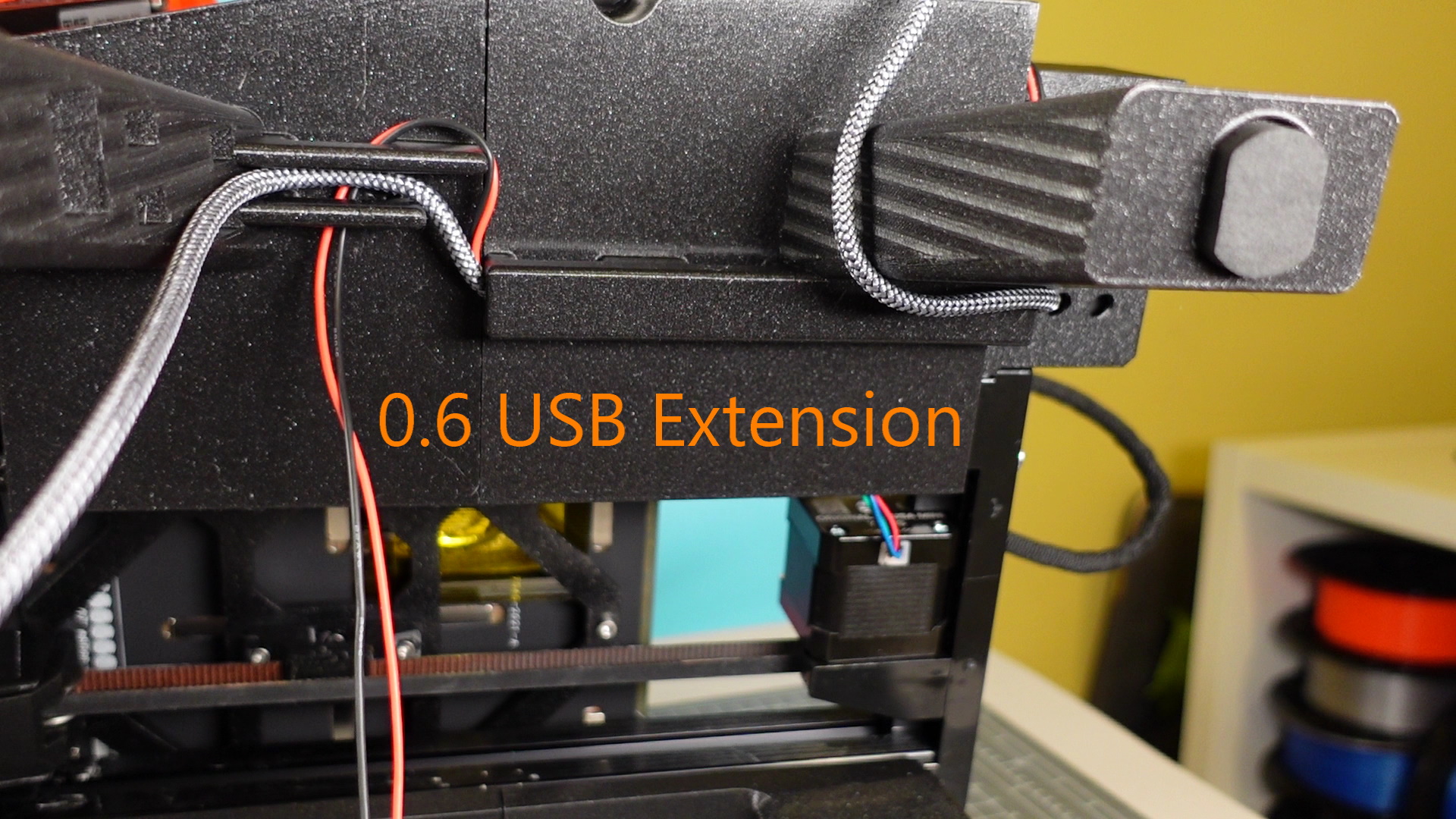
- 0.6m Male to Female USB Extension Lead
- Two wires 85cm in length (to extend the on/off switch)
- M3 * 12 Inner Hexagon Screws x Qty 2
- Cable ties
- Quantity 12: Round magnets size 5 x 3mm
You may be worried about the extra weight on the X-axis. Don’t be, I made those parts as light as possible and then checked with the Prusa devs about the small additional weight. They gave me the all-clear. Also, I’ve designed the eyes so they’re easily removable from the X-axis. This way, you can always take them off in about ten seconds before starting a print if you are still concerned.
All required printed parts fit on a Prusa Mini+ build plate, for obvious reasons, and it shouldn’t take any more than an hour at a relaxed pace to complete the assembly once all the parts are printed.
Please note that you are installing this add-on at your own risk. Any problems or damage caused by the installation are not covered by the warranty and before packing and shipping the printer for repair, this add-on must be fully uninstalled. Also note, I am not personally liable for any problems or damage caused by the installation of this add-on.
Now that the legal speak is out of the way, let’s get on with the build!
- Material recommended: A combination of Prusament PETG Galaxy Black and Prusament PETG Prusa Orange and Prusament White. Several of the parts can also be printed in PLA as these are purely aesthetic. These colours are only recommended, so feel free to go rainbow crazy if you like.
- Total weight: 1700 grams approximately
Material wise PETG is ideal for the legs, LCD screen holder, and x-axis motor cover due to its strength and durability. You can use PLA if you prefer, but it’s not recommended. However, the shoes, Y-axis cover, and eyes can be printed in PLA. Strength and durability are not really needed for these parts.
The file names will specify if and what types of supports are required. Also, a number of parts require colour changes in Slicer. The file names will specify at what heights to initiate the colour changes, as well as the recommended colours required for this. If you are unsure how to set up colour changes in PrusaSlicer, please check out the this article.
Assembly Instructions
I recommend watching the Youtube video bellow and then following the steps and images below. Some of the steps in the video are a little out of sync compared to what’s listed below, but whether you follow the order here or in the video you should be successful. It’s my first video, so be nice. 😊
If you have any questions about this build or are unsure about anything then please feel free to DM me through Printables via my profile. I want you to print and assemble this add-on successfully, so I’ll be more than happy to help out if you are unsure about anything.
Let’s get started!
1. Print all the parts from here: Original Prusa Mate MINI Add-On
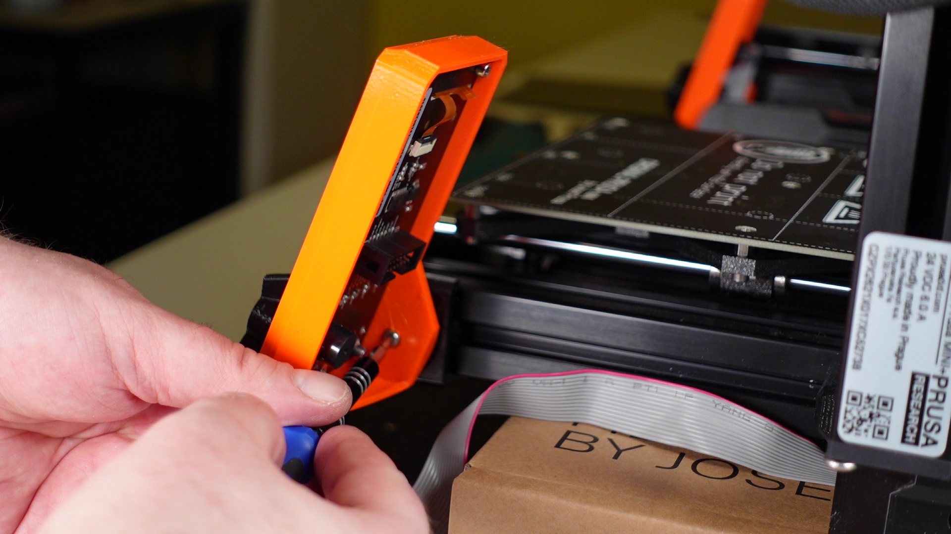
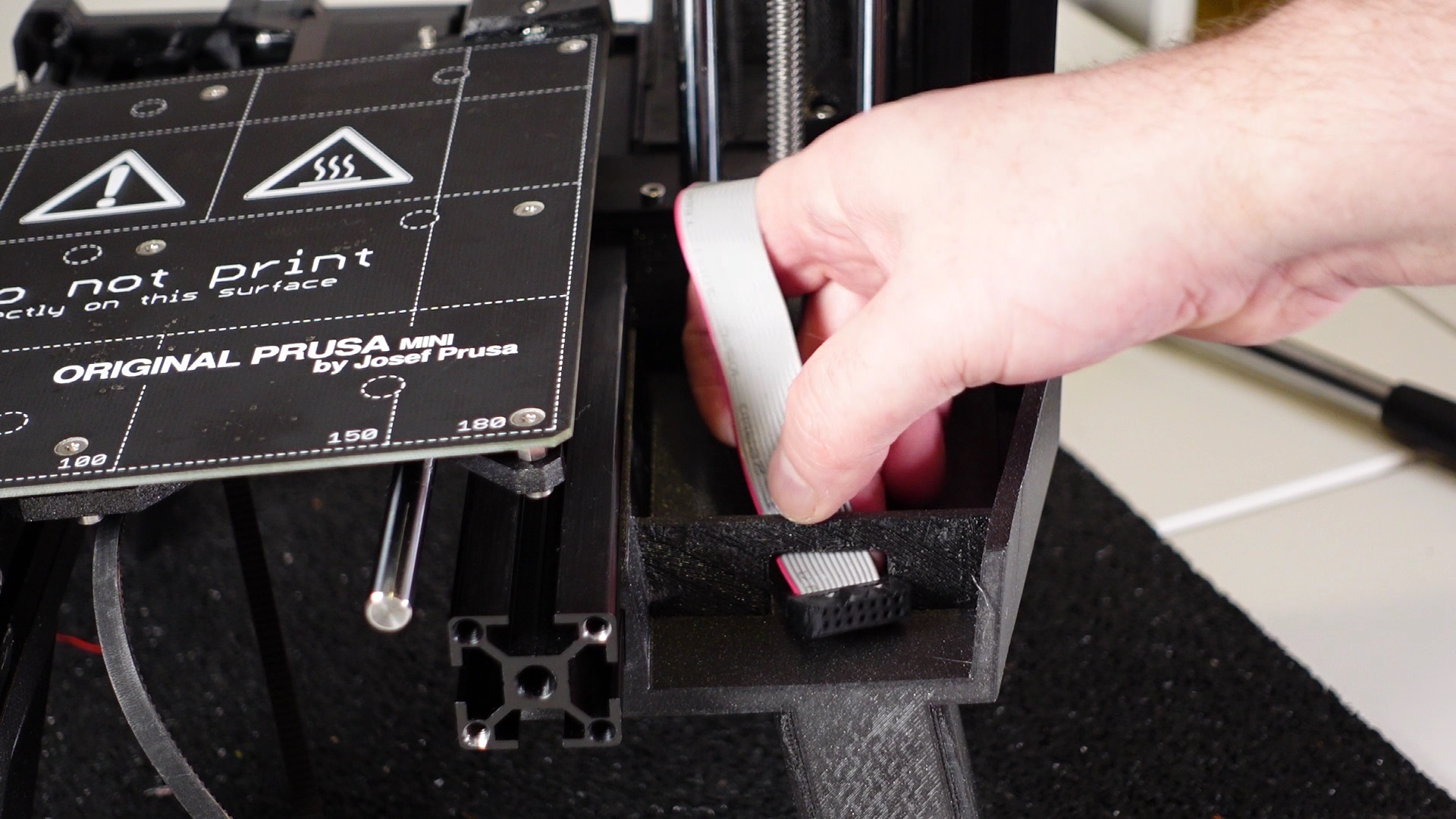
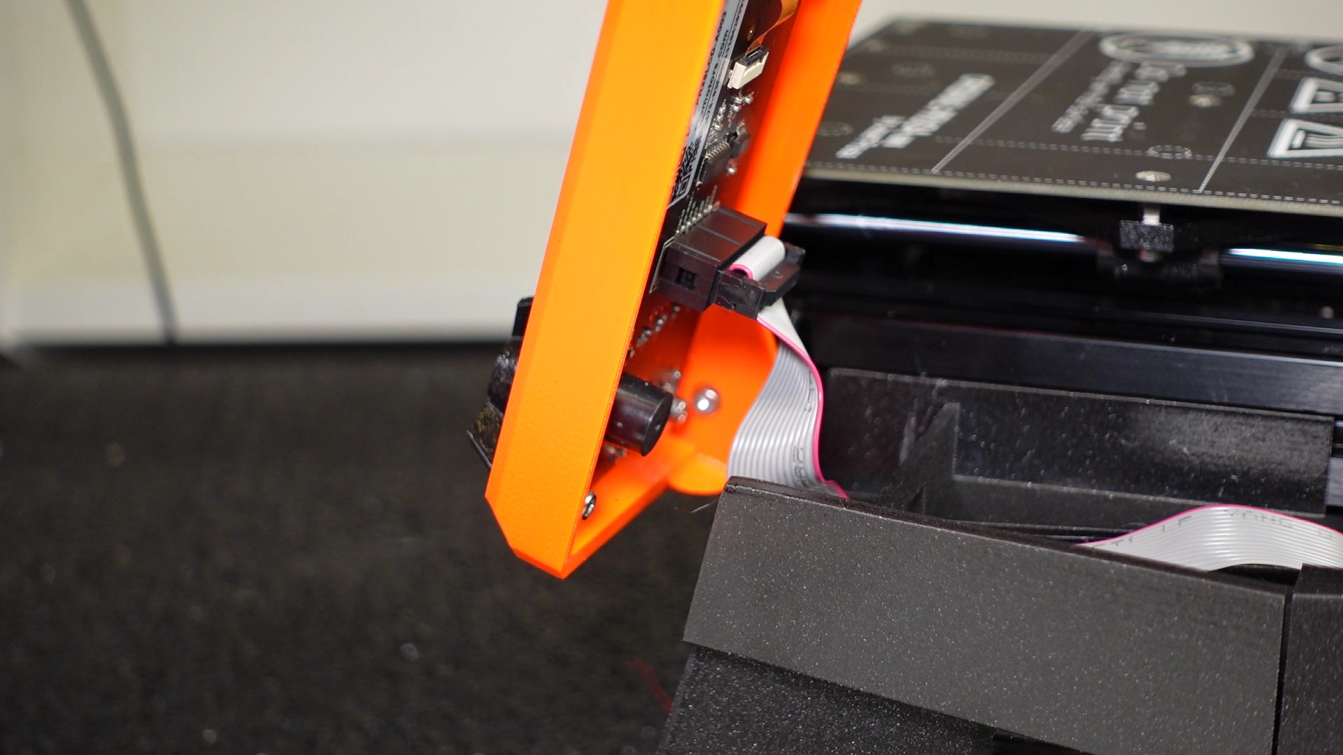
2. Carefully disconnect the power cable and LCD display cable.
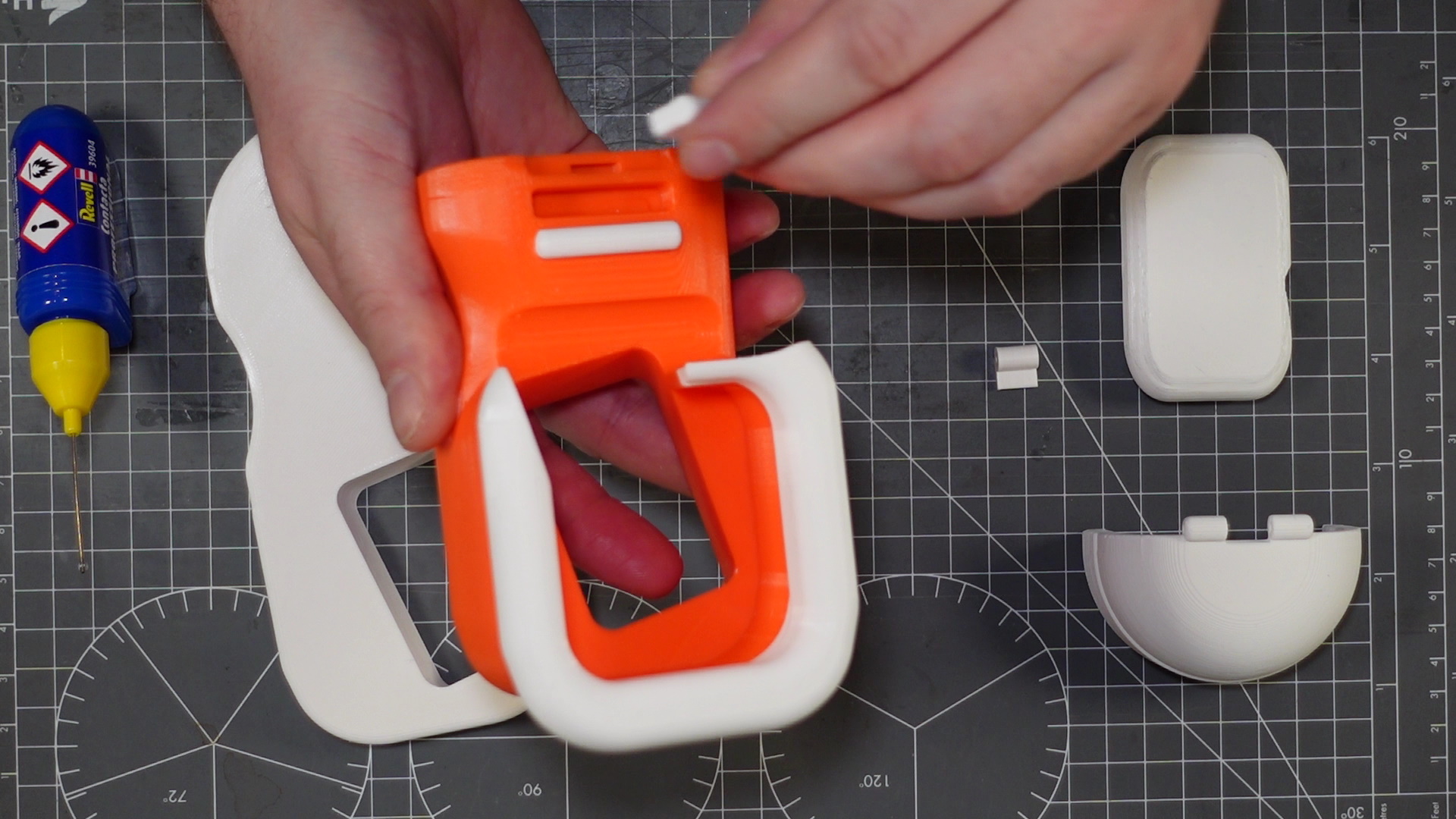
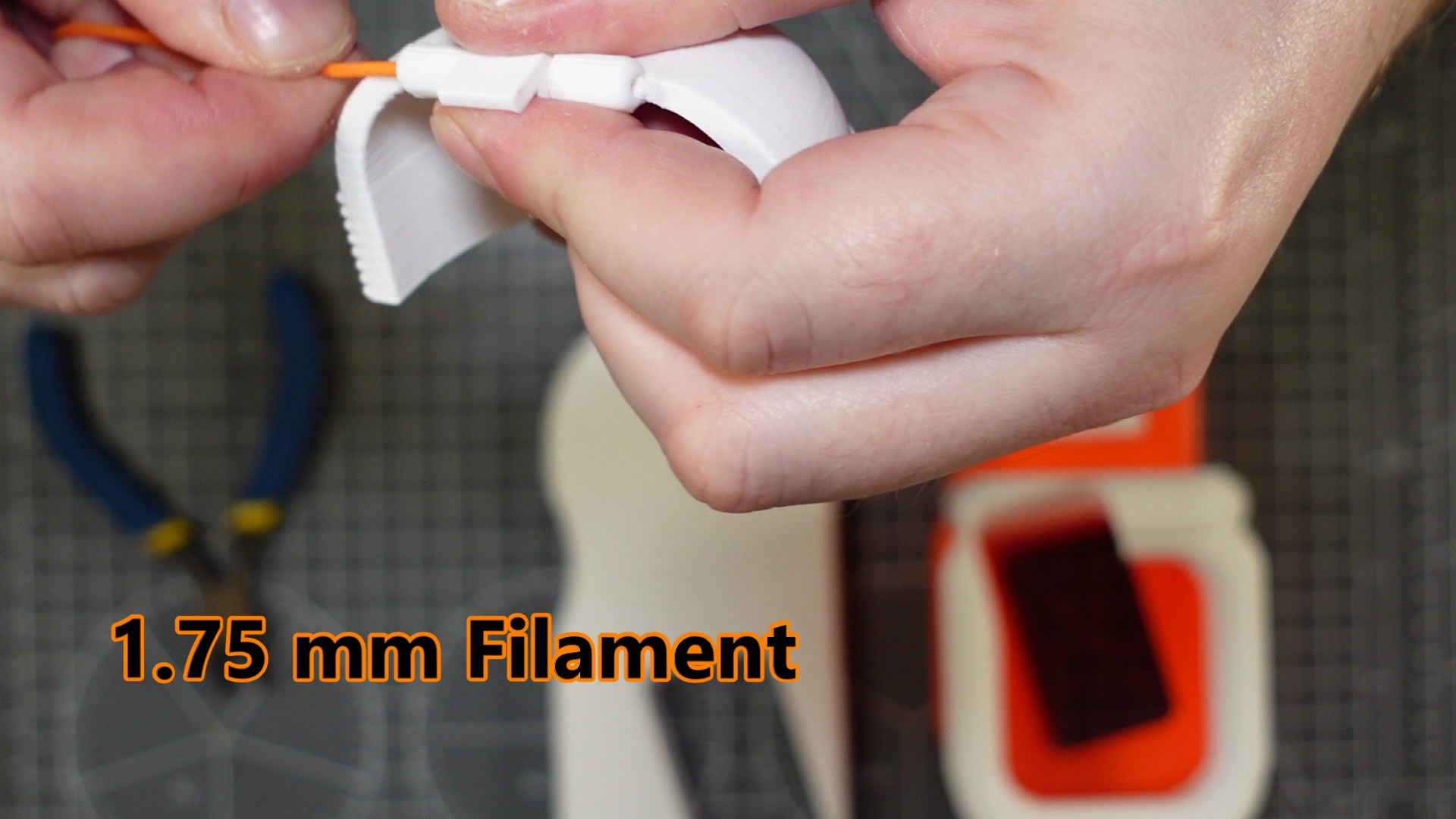
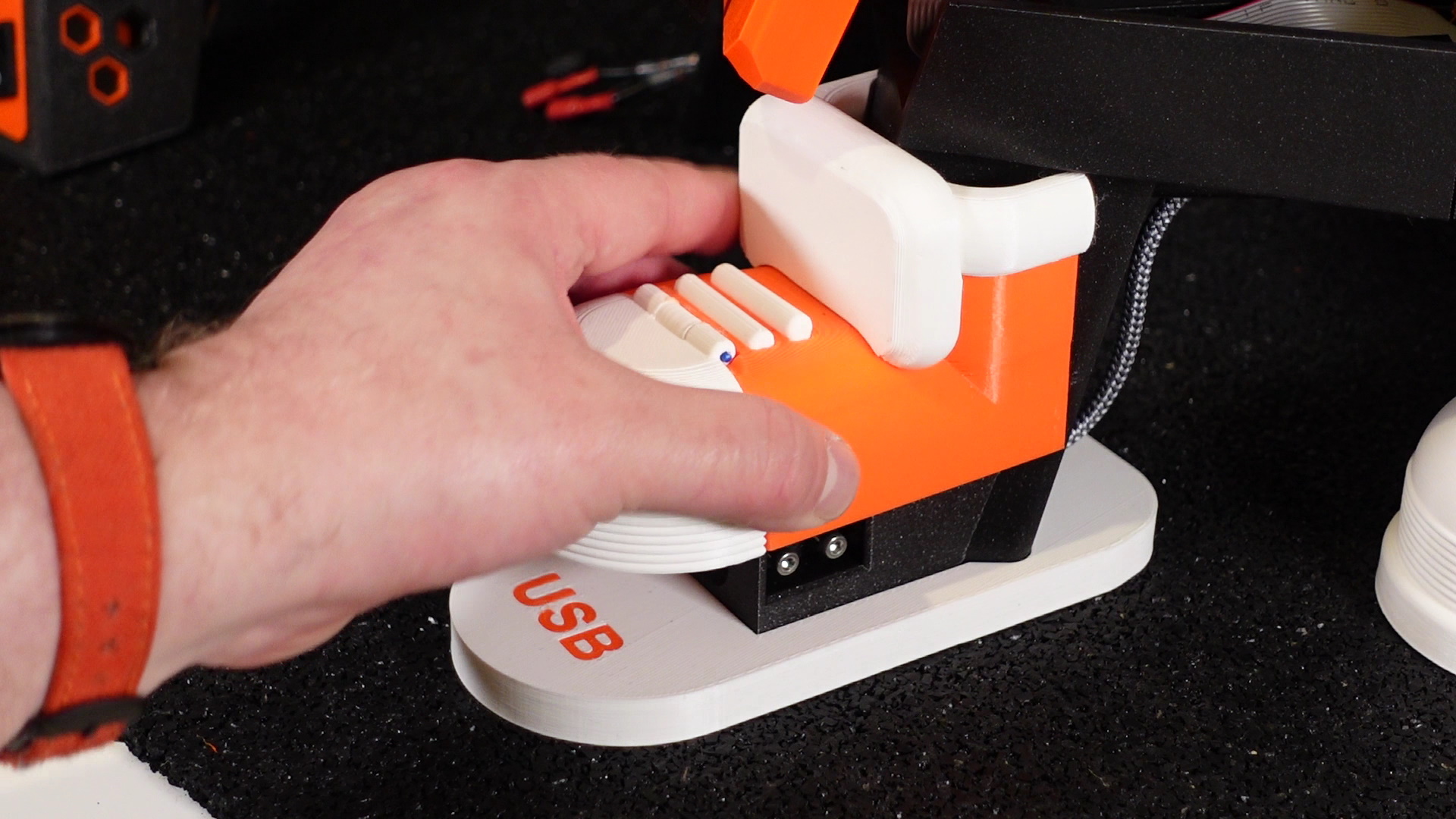
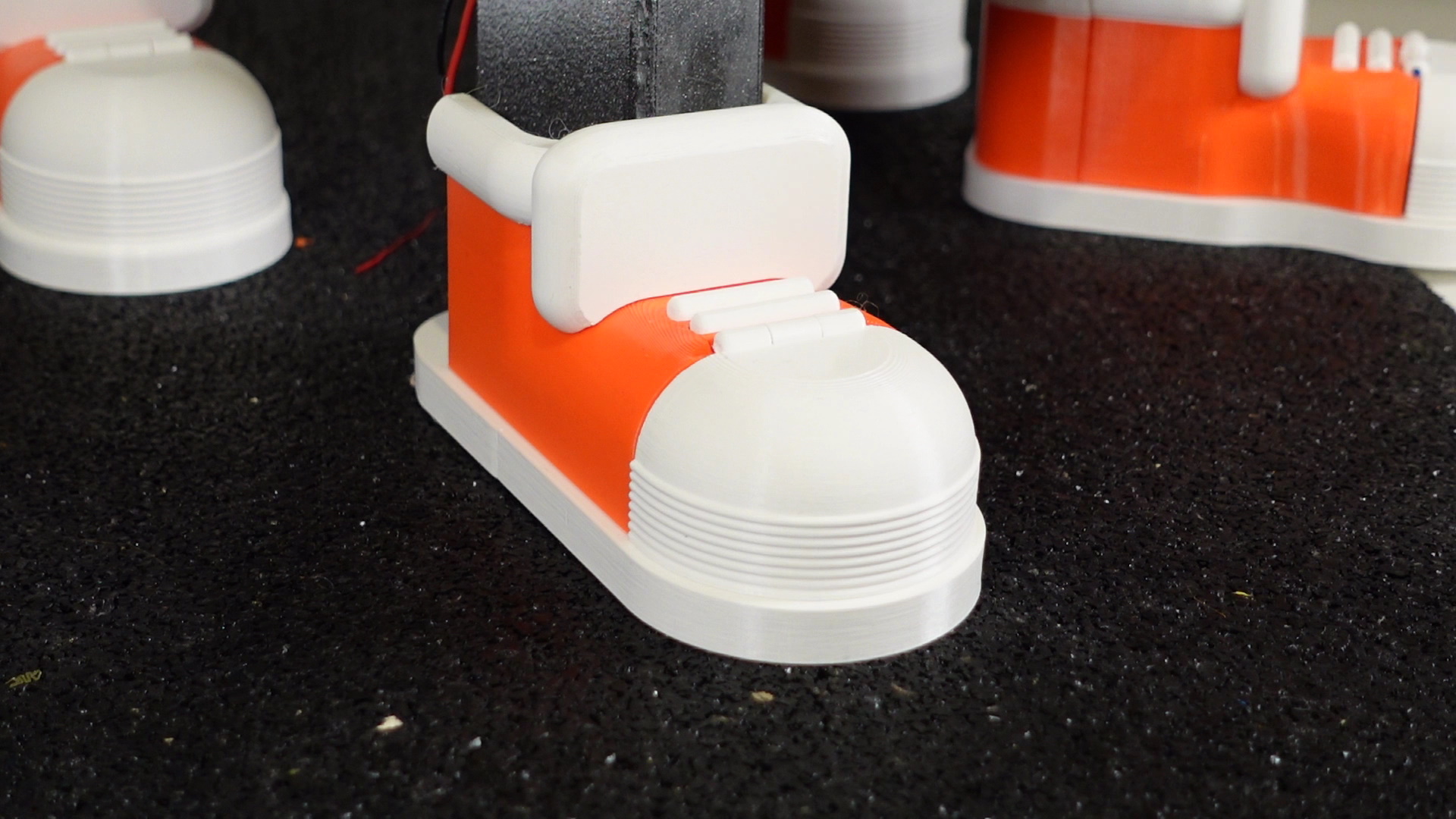
3. Glue the laces and tongue onto the shoe body. Use 1.75mm filament as a hinge pin to attach the front white section of the shoe to the connector. Then glue the connector into the slot in the front of the shoe body. Do this for all shoes.
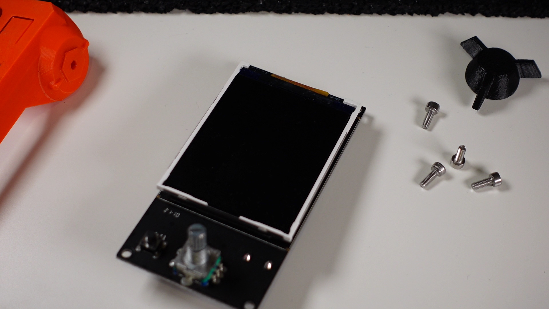
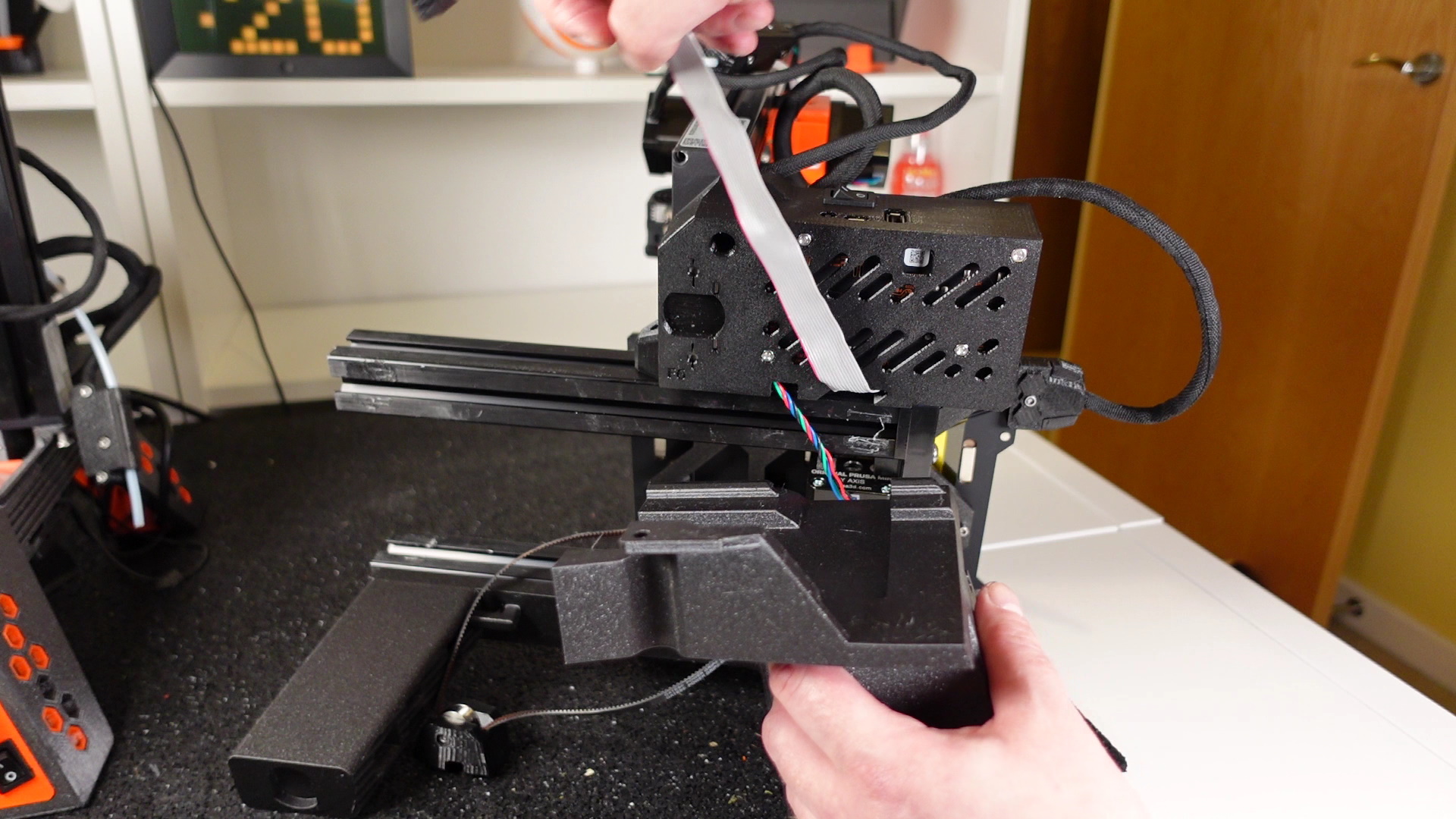
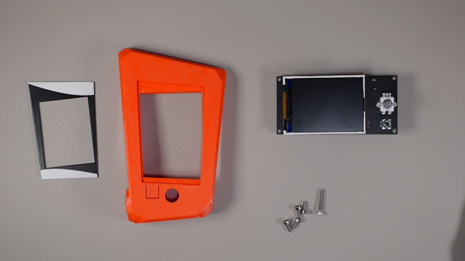
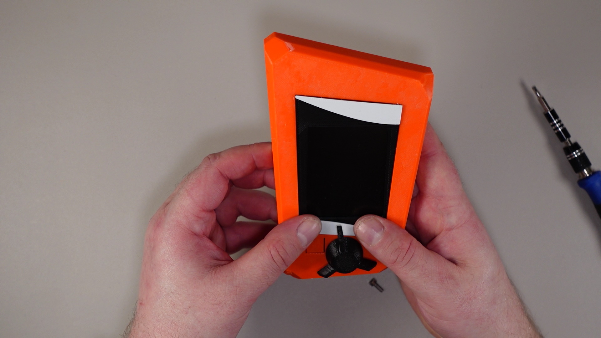
4. Remove the LCD knob and then using a 2.5mm Allen key unscrew the LCD holder from the Y-axis plate. Then remove the four corner screws to remove the LCD display from the holder. Keep the LCD display, screws, and LCD knob safe on the side we’ll be using them again later.
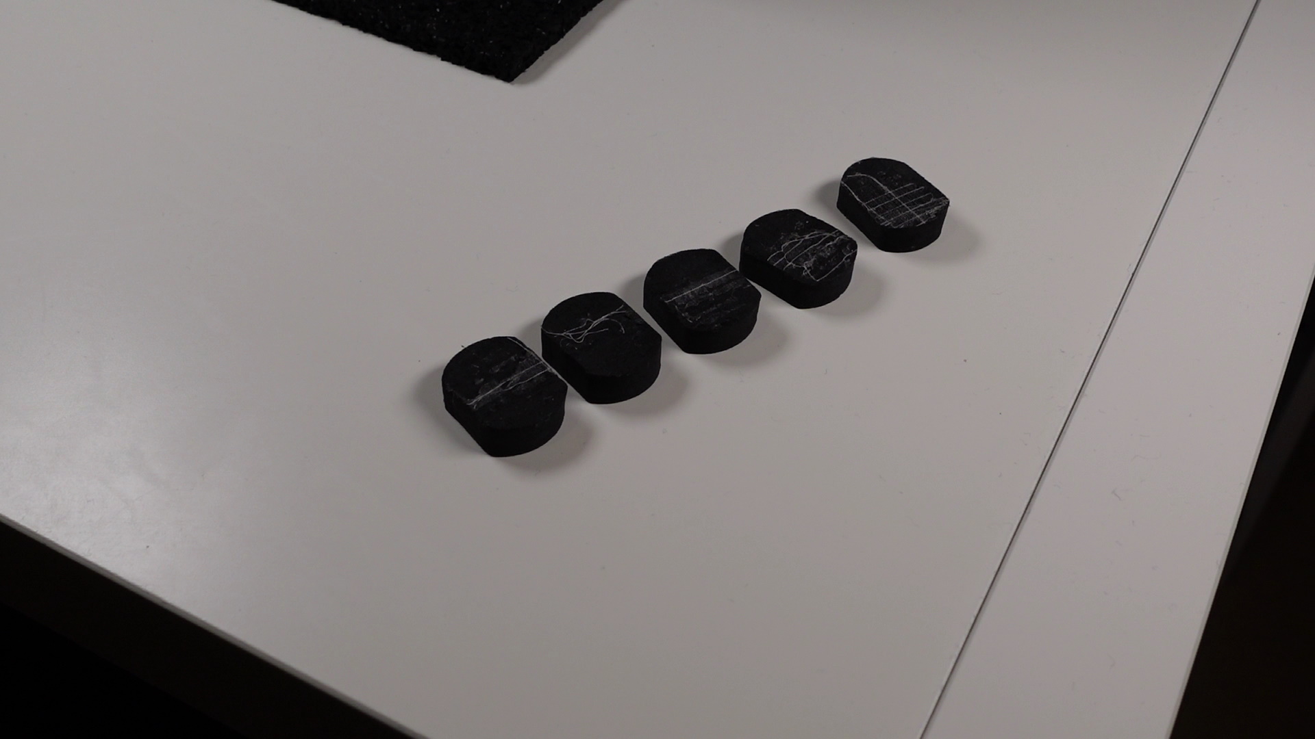
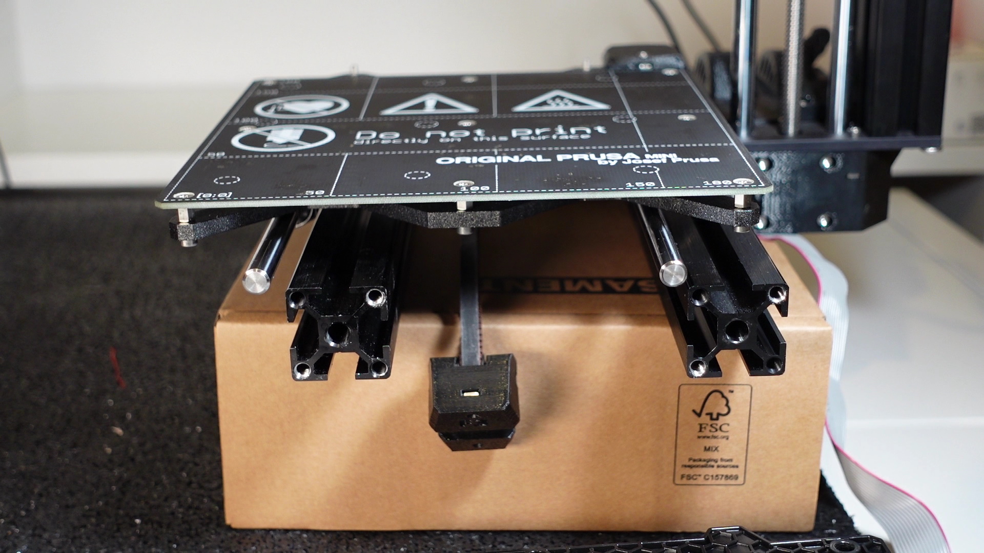
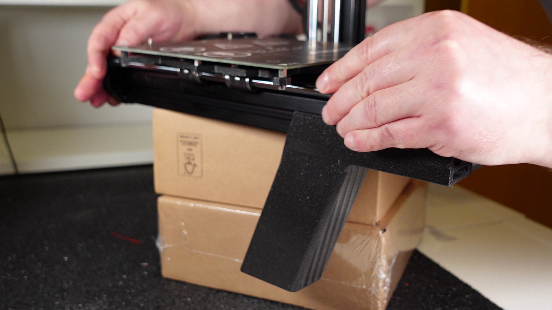
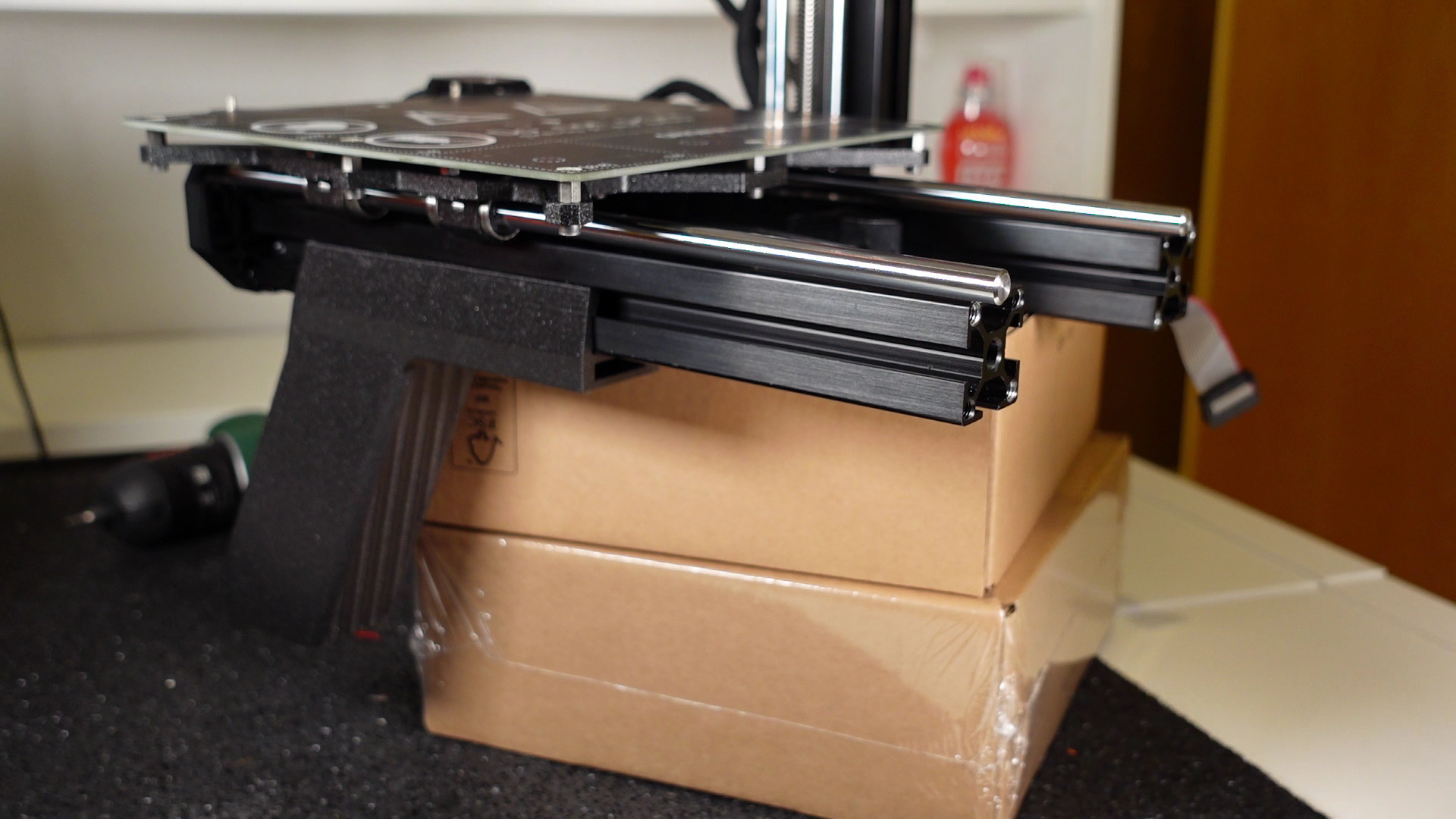
5. Place the printer sideways and remove the anti-vibration pads. Place these onto the cut outs in the bases of the legs.
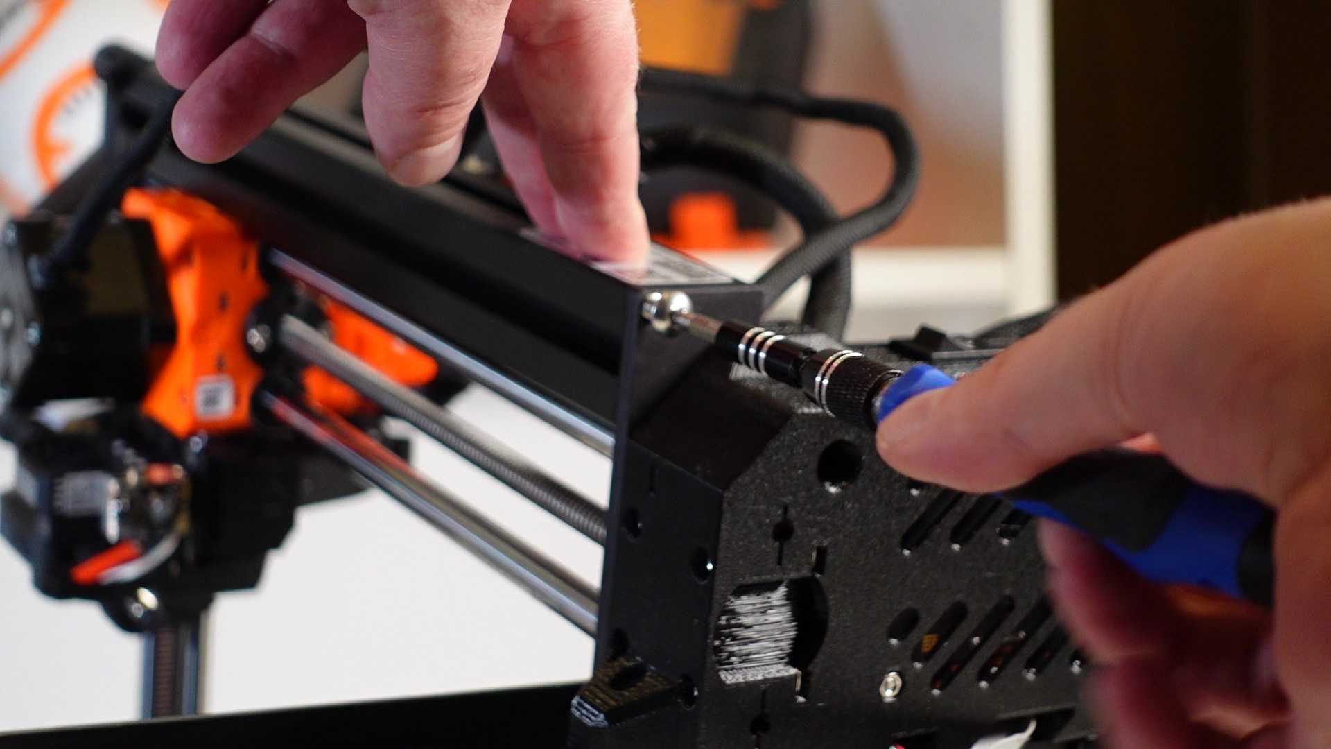
6. Remove the screw from the bottom of the Z-axis extrusion. Again, keep this to the side as you’ll be screwing this back in place later.
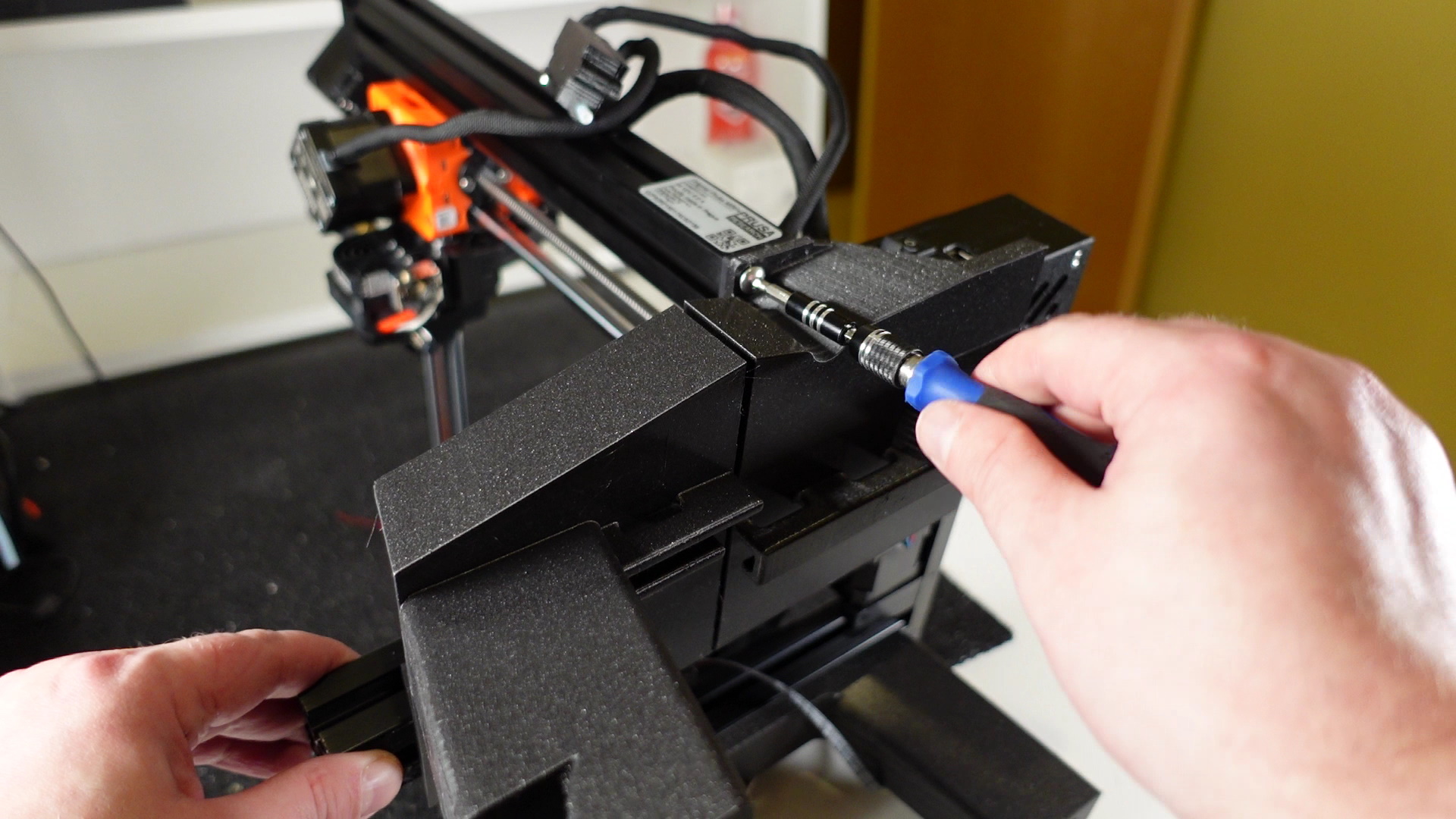
7. Unscrew the front part of the Y-axis. There are four large screws holding the part itself and two smaller screws holding the Y-belt idler. You will need 3mm and 2.5mm Allen keys for this. Keep the screws to the side to reattach the Y-plate later.

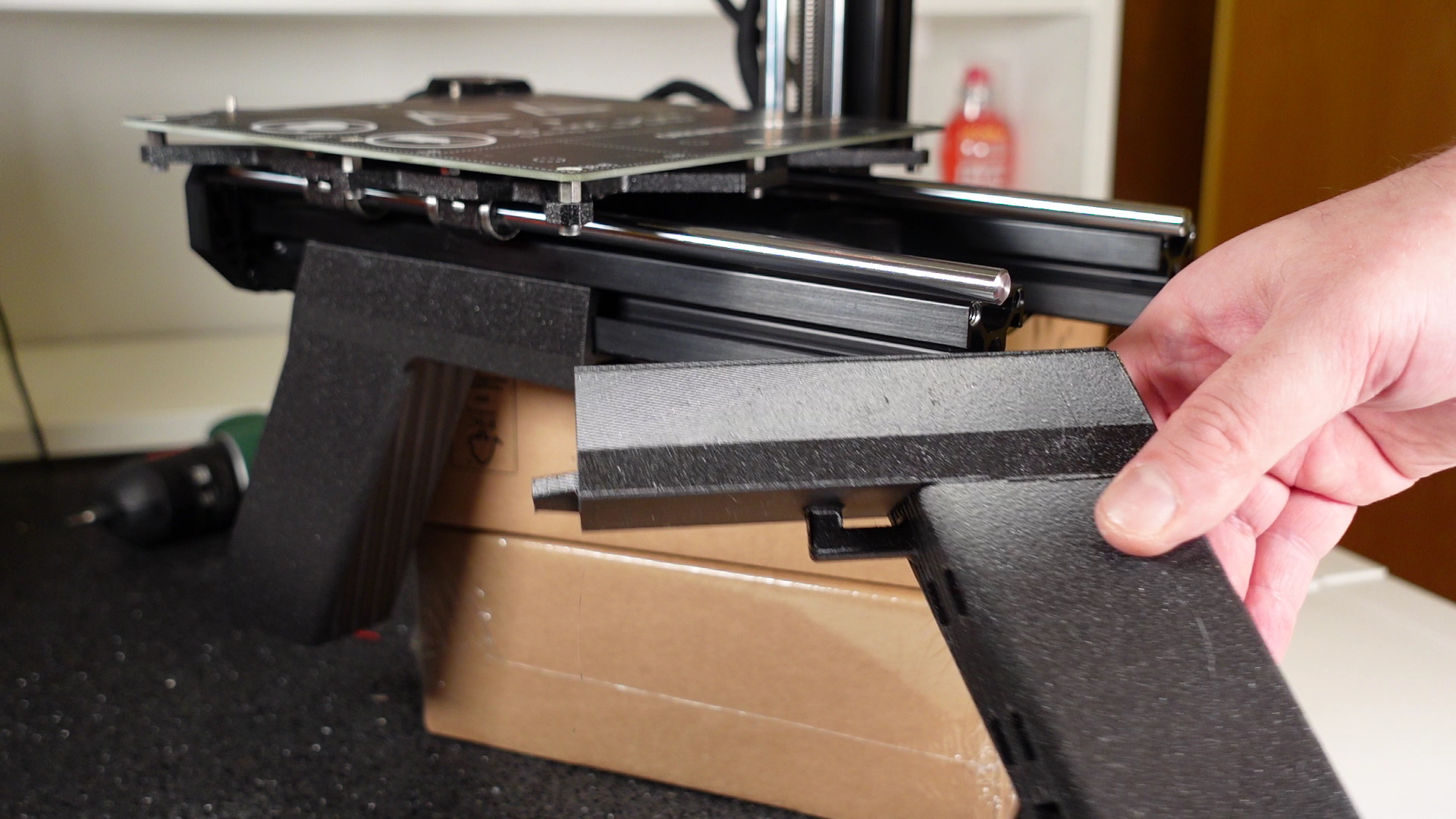
8. Add the right front and right rear leg. (Right and Left legs have been specified as though you were staring at the printer’s backside.)
These just slide back on the right Y-axis extrusion. Once again, a little elbow grease may be required for this part. I have the upper body strength of a ferret, so I did tap the parts in using a small rubber mallet at times, although I did do this very CAREFULLY!
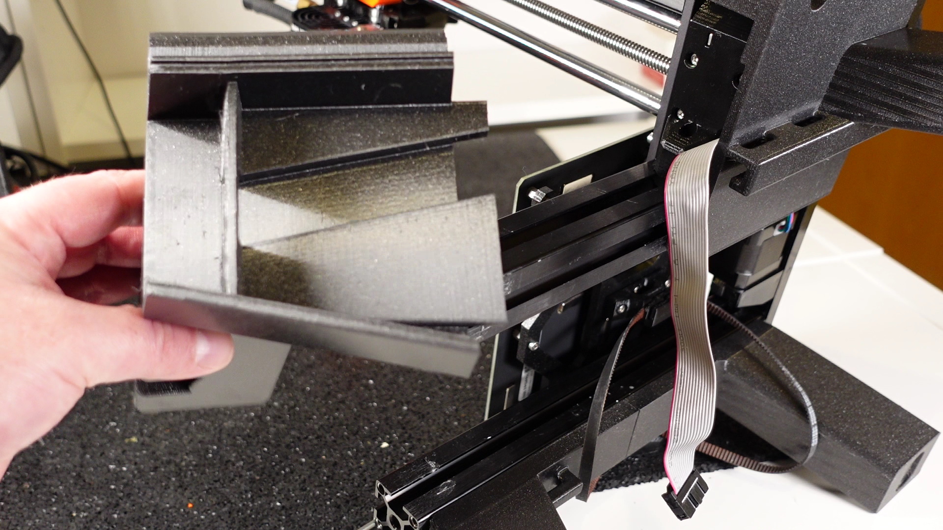
9. The rear left leg slot into the left Y-axis extrusion. Make sure you do not pinch the LCD cable and motor cable as you do. I found this step easier to slot in from an angle and slowly bring down while pushing the parts slits within the extrusion. It should be a firm grip when in place. Once in, slide the part carefully back or forth slightly till you match the hole with the extrusion hole.
10. The front left leg slides into the Y-axis extrusion from the front. (This may be a little tight but with a little effort will fit.) Just slide it back so it’s pressed against the rear left leg, without catching the LCD cable. The cable will fit into the groove on the front left leg passing through the little opening provided on the part. Add the screw back into Z-axis extrusion through the hole in the rear left leg.
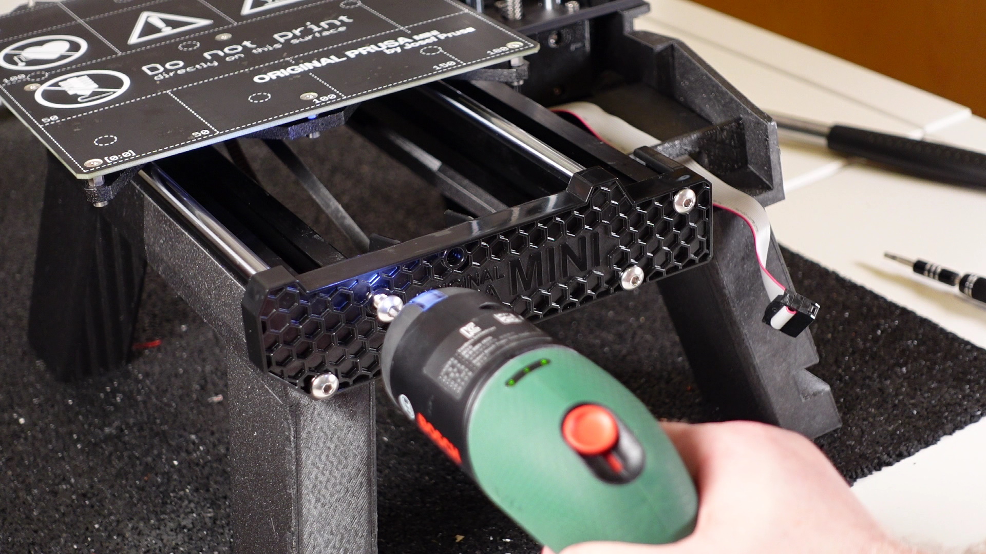
11. You can screw the front part of the Y-axis plate and the Y-axis idler back on.
The next steps (12 to 17) are for moving the on/ off switch and the USB extension. These steps are optional and can be skipped if you prefer. If you do not wish to move the on/ off switch and add a USB extension lead, then please skip to step 17.
12. I actually straight-up copied this step from the Mini Base build article.
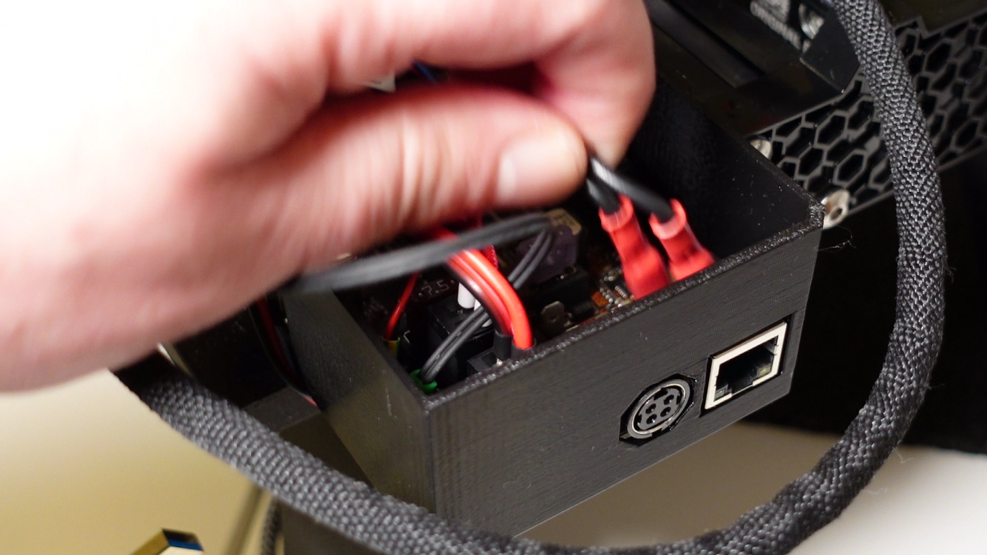
Open the printer electronics box, then disconnect and remove the power switch. You can use Chapter 5, Steps 8 and 9 of the MINI+ kit assembly guide for reference. There is a safety latch on the side of the switch – press it to remove the switch from the electronic box. Connect the new 85cm cable with Fastons.
Note that in the video, I extend the power cable by soldering/heat shrinking, however, this is only necessary if you can’t find a cable long enough or want to reuse old cables for some reason.


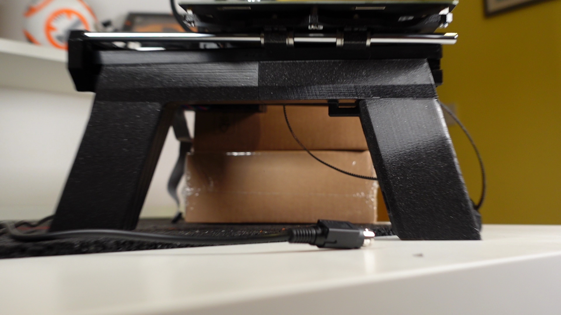
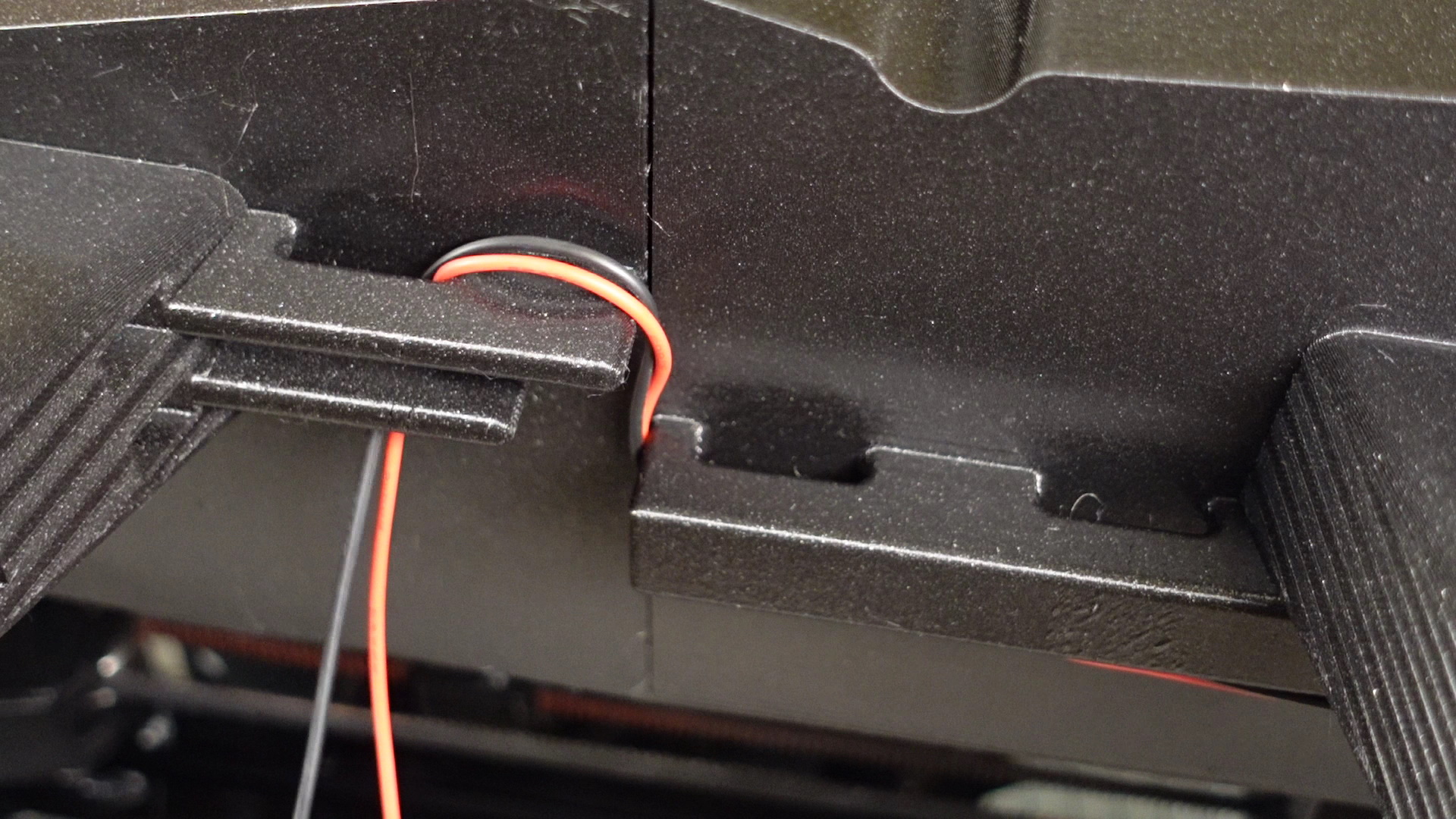
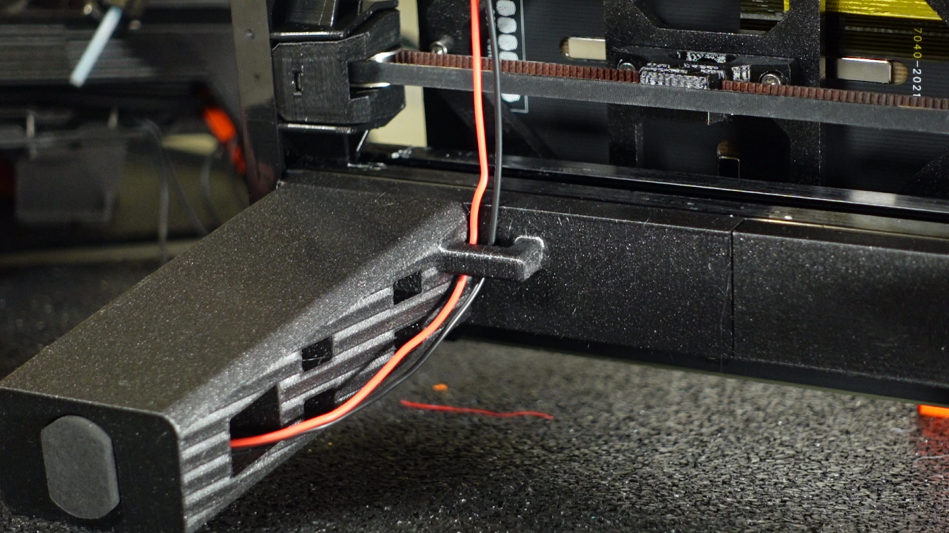
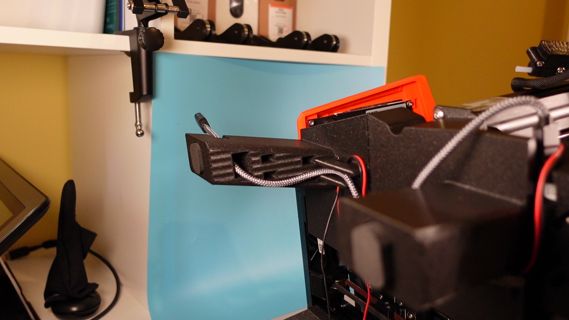
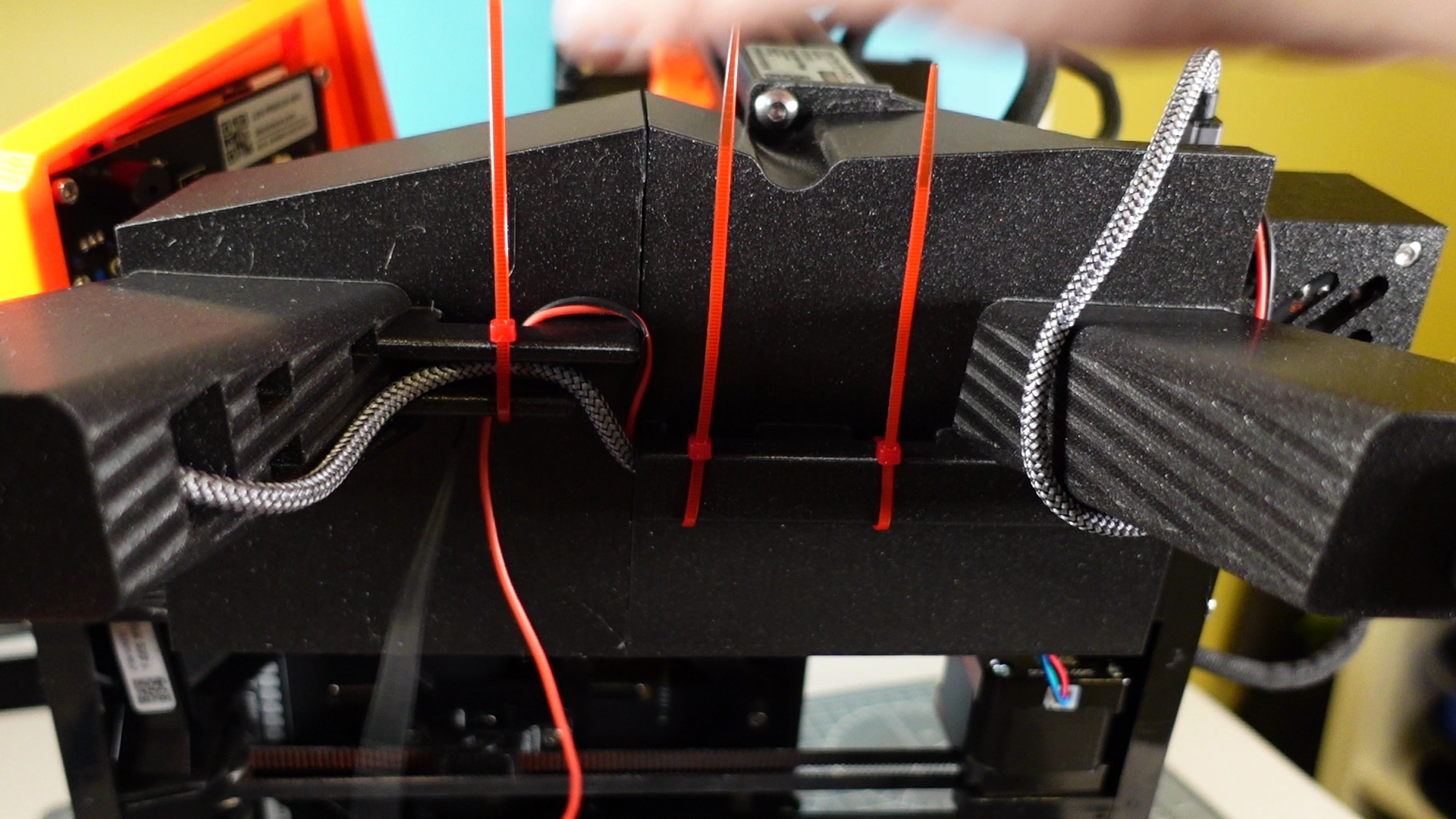
13. Plug the new power cables into the buddy board and pass through the hole where the on / off switch used to be. Wrap around the back of the back left leg and insert the cables into the groove in the underside of the rear left leg. Then pass through the groove hole of the left front leg and then the hole of the right front leg, as per the images provided. This part might be easier to see in the video.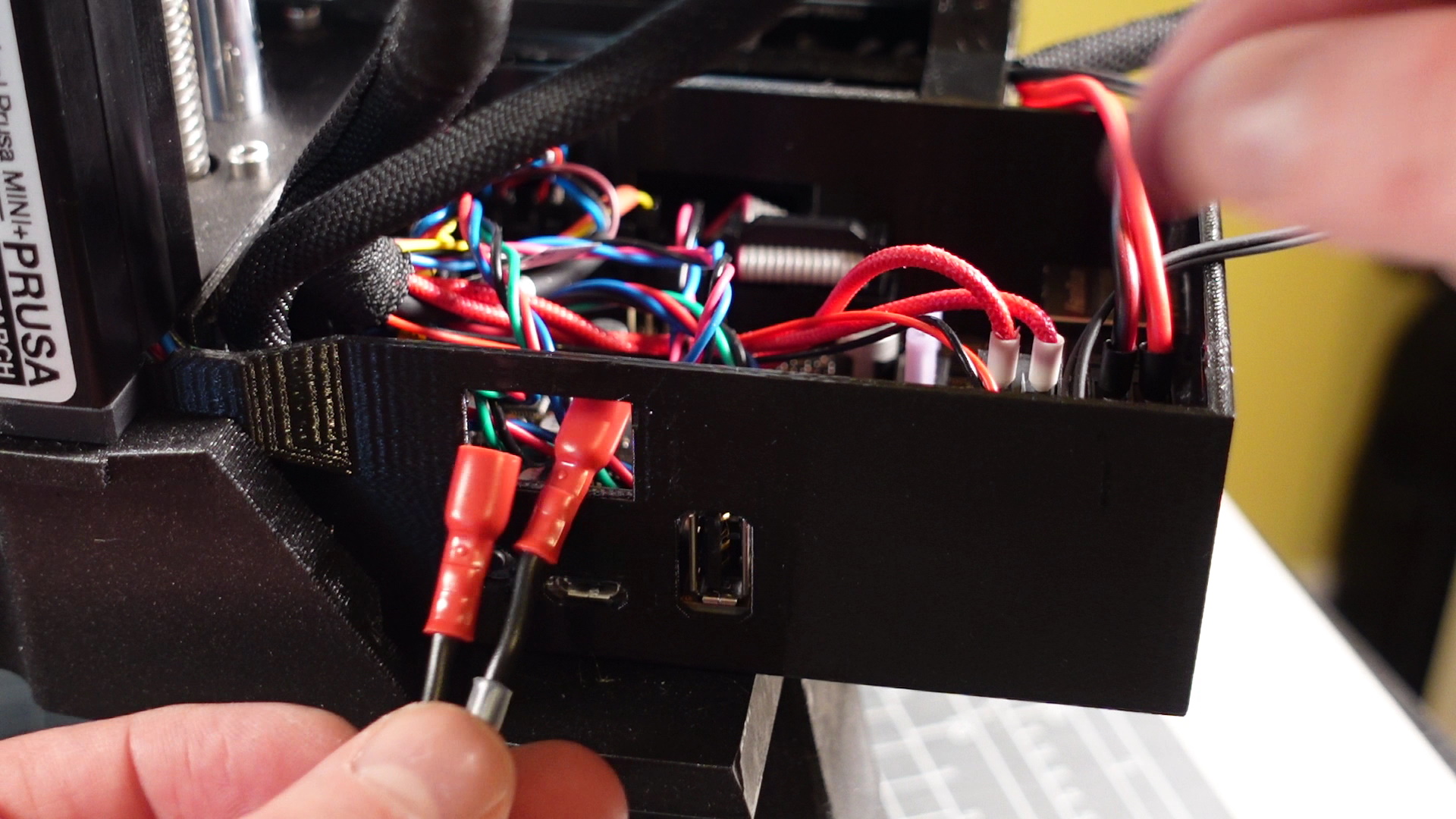
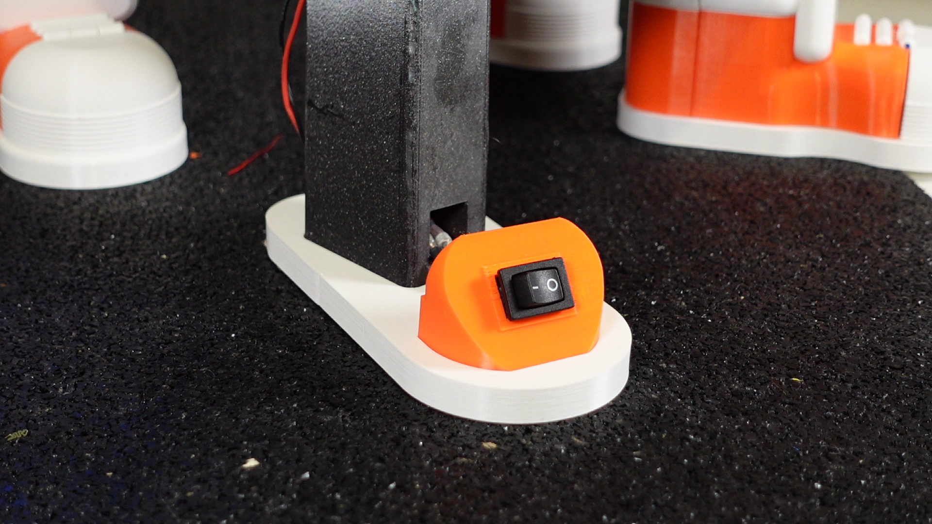
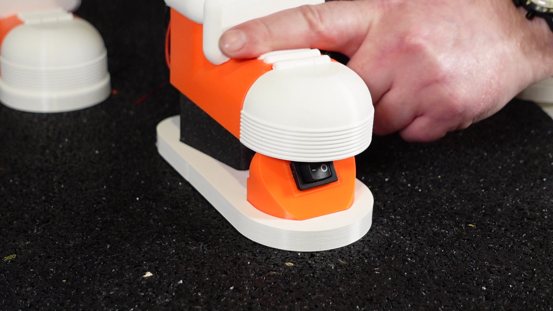
Bring them down and pass through the hole at the base of the right front leg and then through the new on / off switch holder. Connect these to the on / off switch and then press this into the new holder. It’s not too tight, so not much pressure is needed. If you like you can plug the power cord back in to test the on / off switch works and is wired the right way round. Just make sure to unplug the power cord again before continuing further.
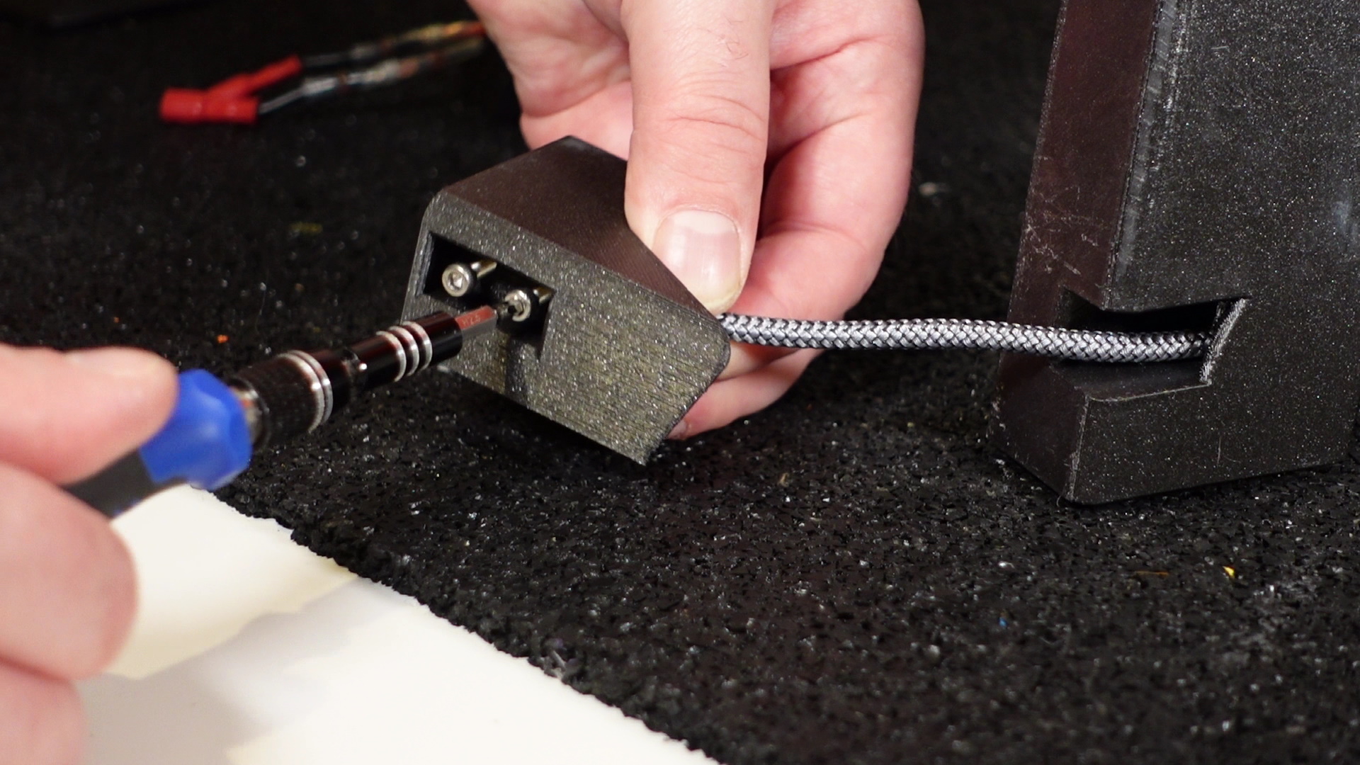
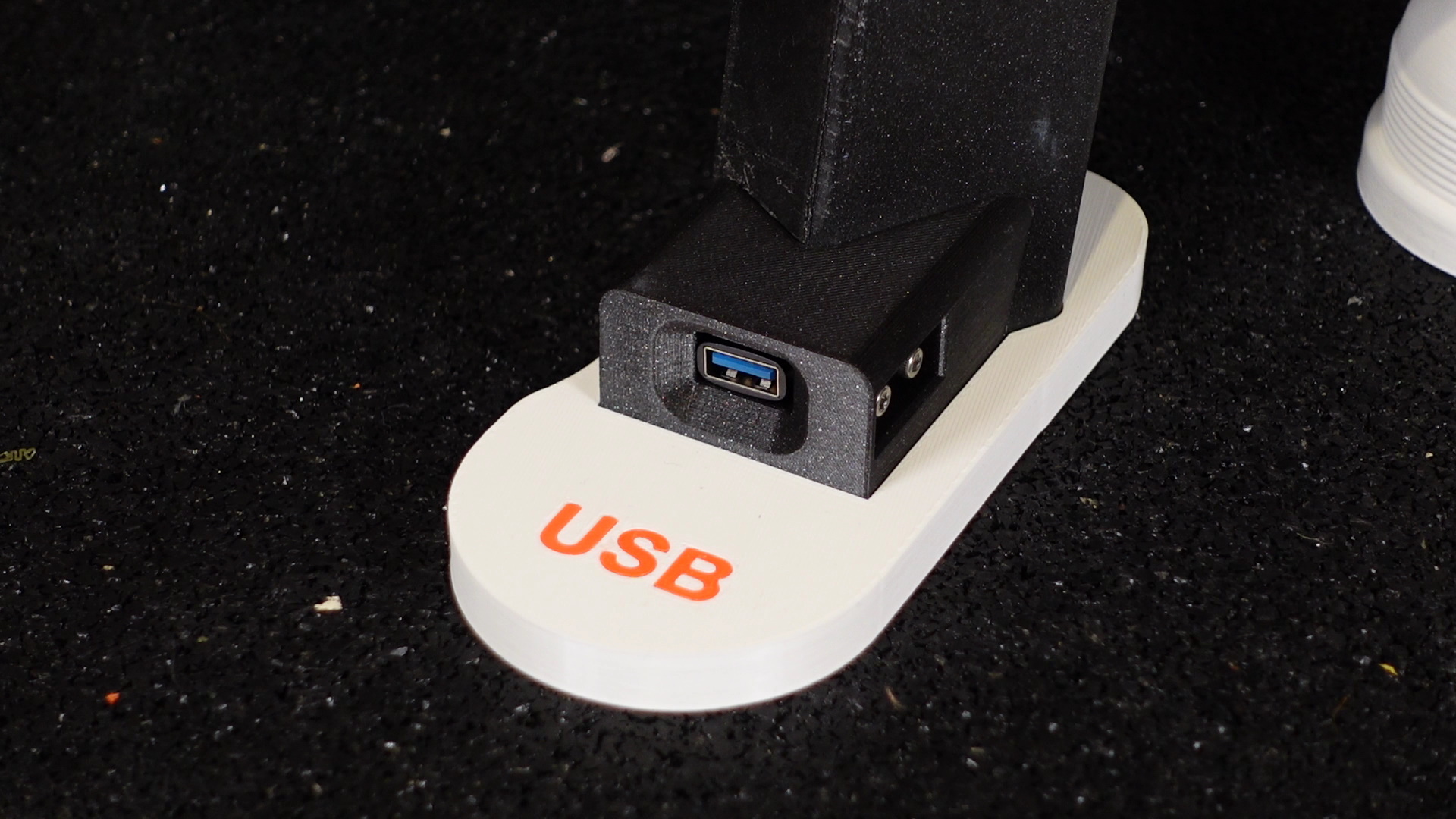
14. Plug the USB extension lead into the USB slot, but this time wrap clockwise around the back left leg, so it’s going in the opposite direction from the power switch wires. Feed the USB extension lead into the groove on the back left leg and then within the front left leg grooves. Bring down to feed through the hole toward the base of the left front leg. The female end of the lead feeds into the USB holder and secure this with Qty 2 – M3 x 12 screws. Pull back on the lead from the backside of the front left leg as you do not want any slack here. The USB holder should be pressing against the leg for the next step.
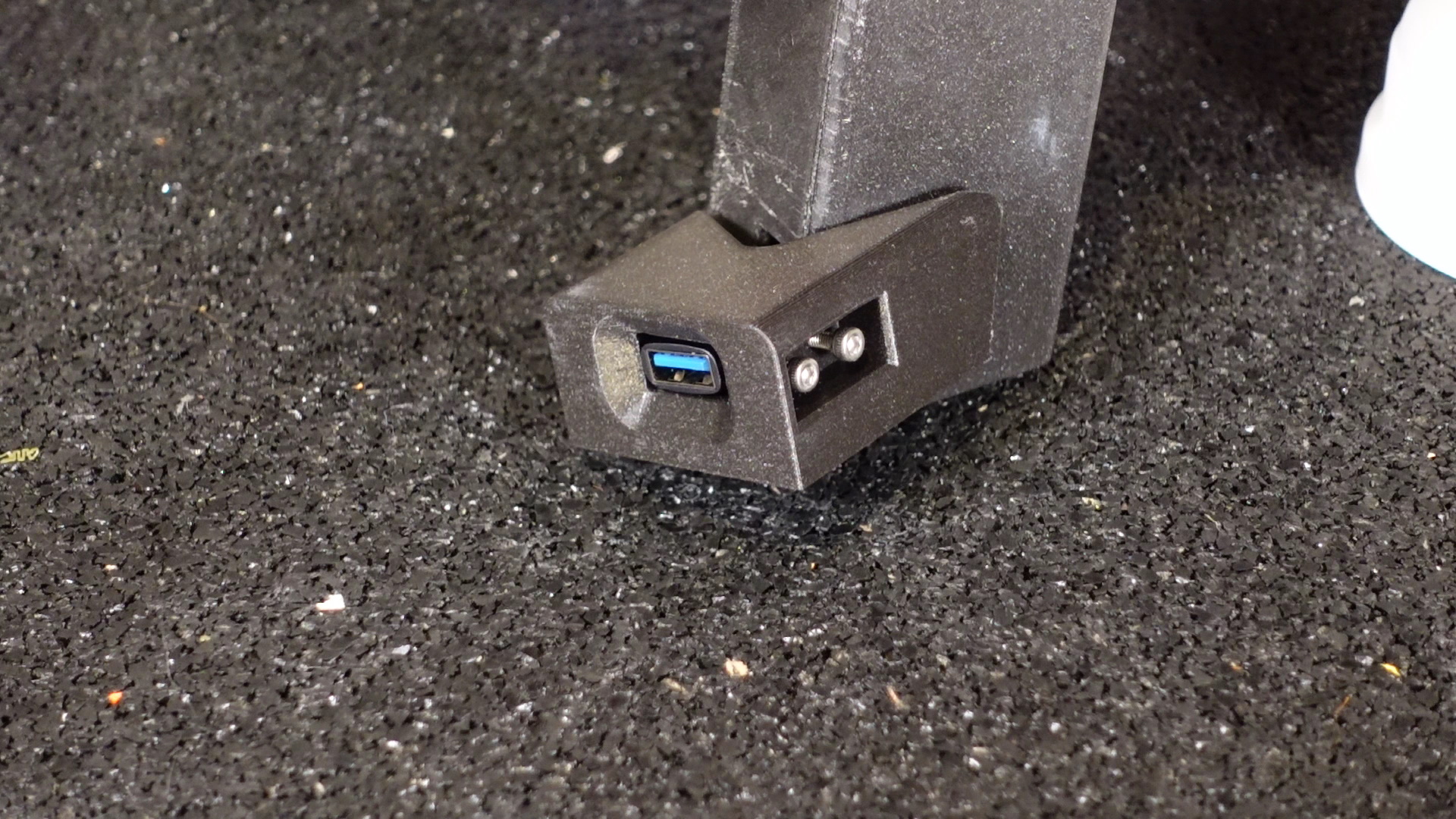
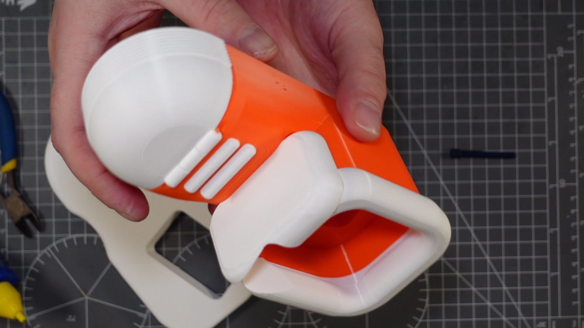
15. Add the soles of the shoes for the front legs and press the USB holder and on/off switch down into the grooves provided on the soles.
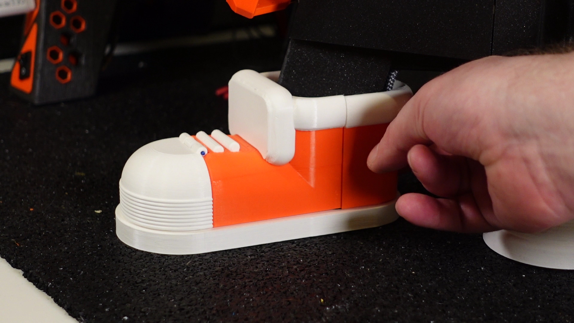
16. The front shoes use 5 x 3mm round magnets to keep the back of the shoes in place. These are easily removable in case you ever need to access the wiring or leads. Twelve small magnets will be needed in total. You just need a little glue to keep the magnets in place. When gluing the magnets in, beware of the magnets polarity and make sure they’re facing the right way, so the front and back parts of the shoes are magnetically attracted to each other.

17. The front shoes slot back against the legs just above the on/off switch and USB holder. Then drop down, holding the on/off switch and USB extension in place. Add the backs of these shoes. As they are magnetized these will be held in place.

18. Use cable ties to tidy the wiring on the underside grooves and down the front legs. Then trim the cable ties down.
19. If you carried out the on/off switch move and USB extension, then you only need to add the back shoes. If you skipped steps 12 to 17 then do this step for all shoes. The shoes slot in from beneath the legs, shoe body first and then soles. Once added and the printer is flat, push the shoes and soles down, so they’re flat against the surface.

20. Glue the black and white part into the front of the new LCD cover and wait for the glue to dry. Place the LCD display into the new cover and screw in the top two screws and bottom left (if you were staring at it from the back). Then screw this back onto the Y-Axis plate. Now add the fourth screw to the bottom right of the LCD screen cover. You can now connect the LCD cable into the back of the screen.
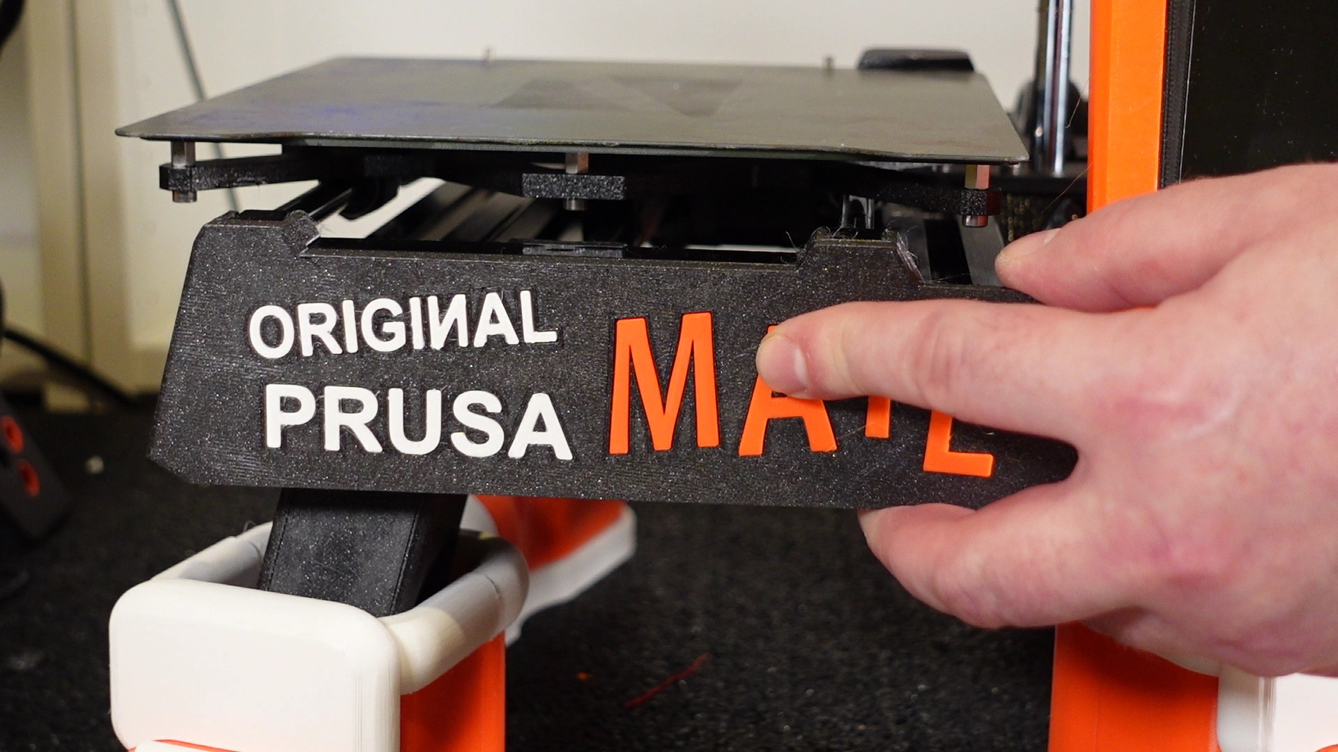
21. Carefully, using glue add the printed words ‘Original Prusa Mate’ into the new Y-plate cover. Then add the new Y-plate. This just slots over the top of the existing Y-plate.
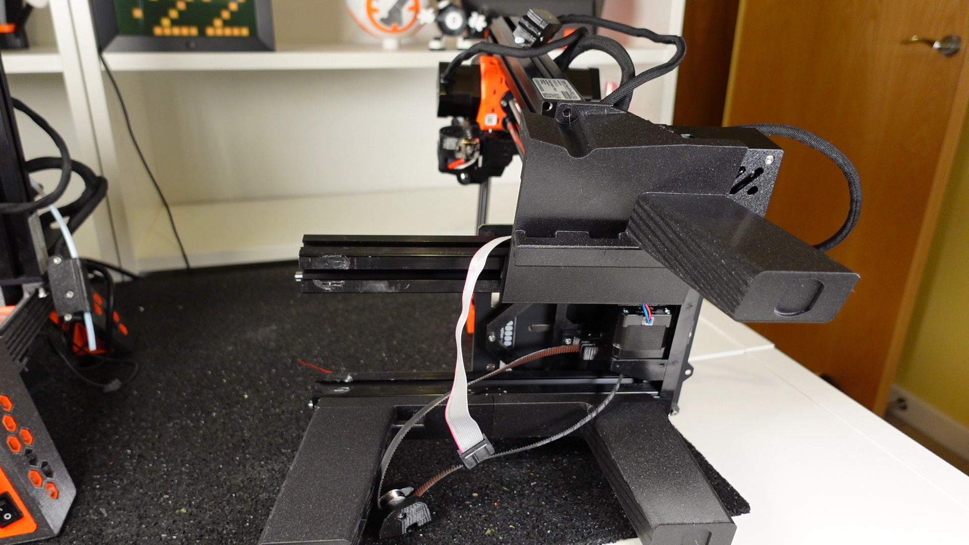
22. Glue the irises and eyebrows to the white eye sections and then connect the white sections together using the small black connector. Slot the motor holder into the side of the eyes as well, with the motor holder facing back. Then fit this over the Z-axis motor.
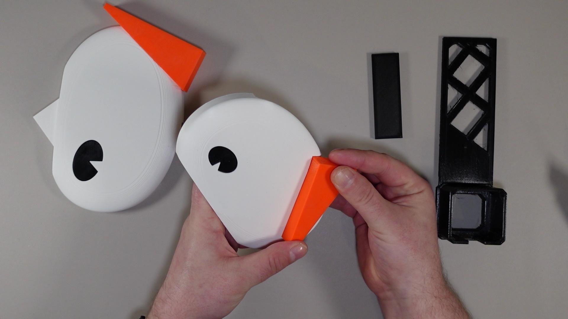

23. Slot the gantry cover and slot this into the eyes insert as well.
24. Add the small pot positioned just behind the LCD screen. This is perfect for storing Haribo or Smarties, just saying. 😊

25. Run the printer calibration again. As we partially disassembled the Y-axis, the printer geometry may have changed slightly. Better safe than sorry.
That’s it, it’s complete. Take pleasure knowing you have the coolest most fun printer around. Please be sure to tag me in any builds you all do or even any prints you make on a completed Prusa Mate MINI. 😊

If you like what I do and want to follow more of my projects give my Printables profile a follow and check out my social media and Patreon, links are below. Special thanks to Prusa Research for this project. Their patience and support with this has truly been remarkable and I am massively grateful.
Enjoy your Original Prusa Mate and as always, Happy printing.
Neil3dprints / Makers Desk
This is incredible! I’ve loved Neil3dprints’s style for a long time. Especially his Little City models and Print A Toons. I love fun prints, and what could be more fun than a real working Prusa Mate? Awesome collaboration!
that’s actually incredible
https://printerflax.com/best-sublimation-printer/
It’s beautiful!
Thanks for the sharing this amazing piece of content.
as a sublimation enthusiast, this is really helpful for me. Thumbs up!
Dragon Trainer
Amazing build! Just add hands!!!
Hi, I know you are busy with understanding the steps of writing, we can help you
write for us development you can earn new skills from there which will increase your carrier opportunity in future.
Hi guys, I am Prachi, thanks for sharing this article. Looking for right immigration consultants for Australia Smart Study will help you to provide Best Canada Study Visa consultants in Ludhiana
Thank you for such an amazing discussion. one piece treasure cruise unlimited gems