


Even though the Original Prusa MINI+ is a compact printer, sometimes you might feel it takes up a little more space than is necessary. There is the filament holder standing nearby, the unwieldy PSU “brick”, perhaps an extra print sheet, USB drives, assorted parts and tools…it all adds up quickly.
Enter the MINI Base!
We came up with a solution, a relatively simple printed add-on that gives your MINI+ a bit of a majestic presence, while actually saving space and neatly organizing the extras your MINI+ needs, all at the same time.
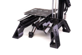
This four-legged beast is designed not only to look cool, but also to provide maximum functionality and storage space for all the goodies mentioned above.
“No legs bad, four legs good!”
– George Orwell, Animal Farm (kinda…)
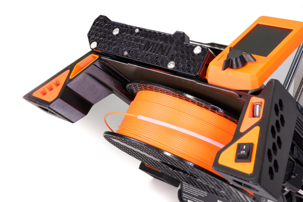
Probably the biggest improvement over the vanilla MINI+ is that with the MINI Base, you don’t need extra space for the filament holder and the PSU, as both the spool and the “brick” are now stored under the printer.
While it makes the MINI+ stand taller, trading width for height is usually a good tradeoff, unless you keep your printer in a short rack or shelf.
Best of all, the assembly is quite easy and only needs a few pieces of extra hardware. In total, it shouldn’t take more than 30-40 minutes even at a relaxed pace.
Some of the steps are optional, for example, the power switch relocation. If you feel uneasy about messing with the power cables (although this step is actually not hard at all), feel free to skip it.
Let’s start!
Please note that you are installing this add-on at your own risk. Any problems or damage caused by the installation are not covered by the warranty.
Also, please note, that before packing and shipping the printer for repair, this add-on has to be fully uninstalled.
Printing All the Parts: Summary
- Material: A combination of Prusament PETG Prusa Orange and Prusament PETG Jet Black
- Total weight: 708 g
- Total printing time: 4d 0h 16m (using a standard 0.4mm nozzle, default PrusaSlicer profile 0.15mm QUALITY, Prusament PETG)
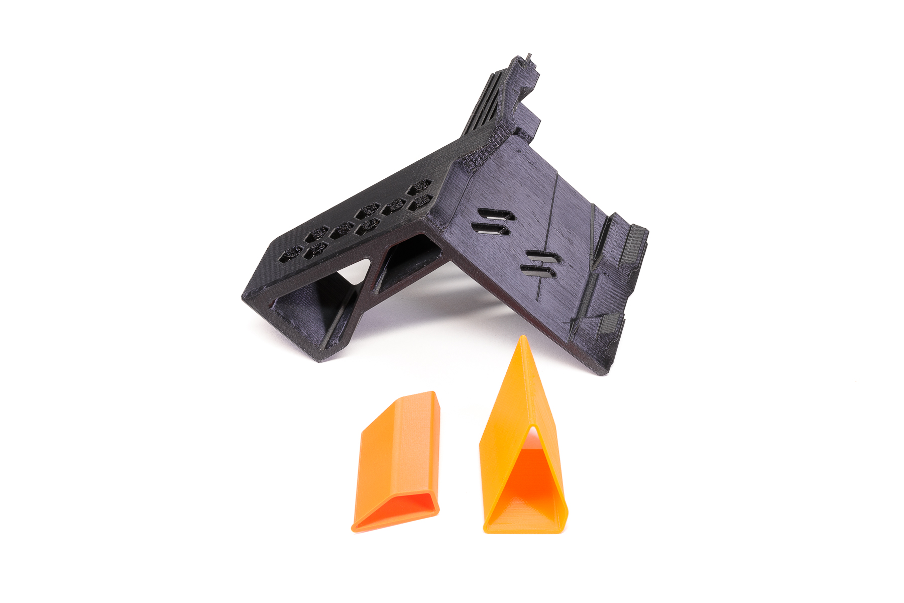
Of course, all parts are designed to be easily printable on the Original Prusa MINI+ itself. No supports are needed, with the exception of one component, the right front (RF) leg.
Note that you can significantly lower the printing time by increasing the layer height (you can easily get away with 0.30mm, we have chosen 0.15mm just so the parts look a bit fancier in the photos 🙂 )
Feel free to use any color combo you like! PETG is an ideal material for such a project, because of its durability. If you must, PLA would do (the parts are not mechanically stressed or subject to excessive heat), but we don’t recommend it.
All 3D models are available on PrusaPrinters as both 3MF and STL files.
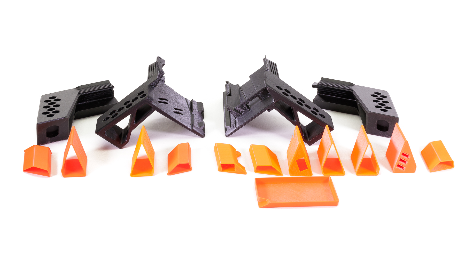
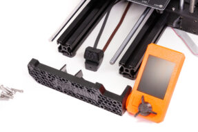
Main printed parts checklist
 |
 |
| All four legs with their various insert options. | |
 |
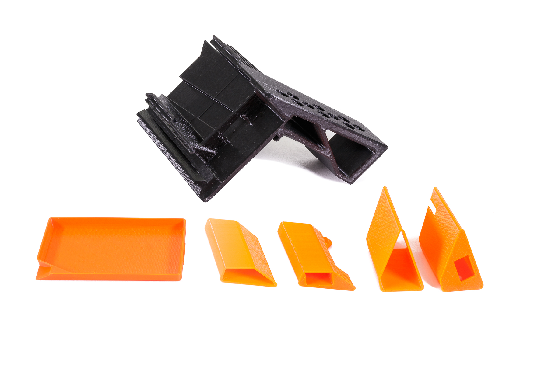 |
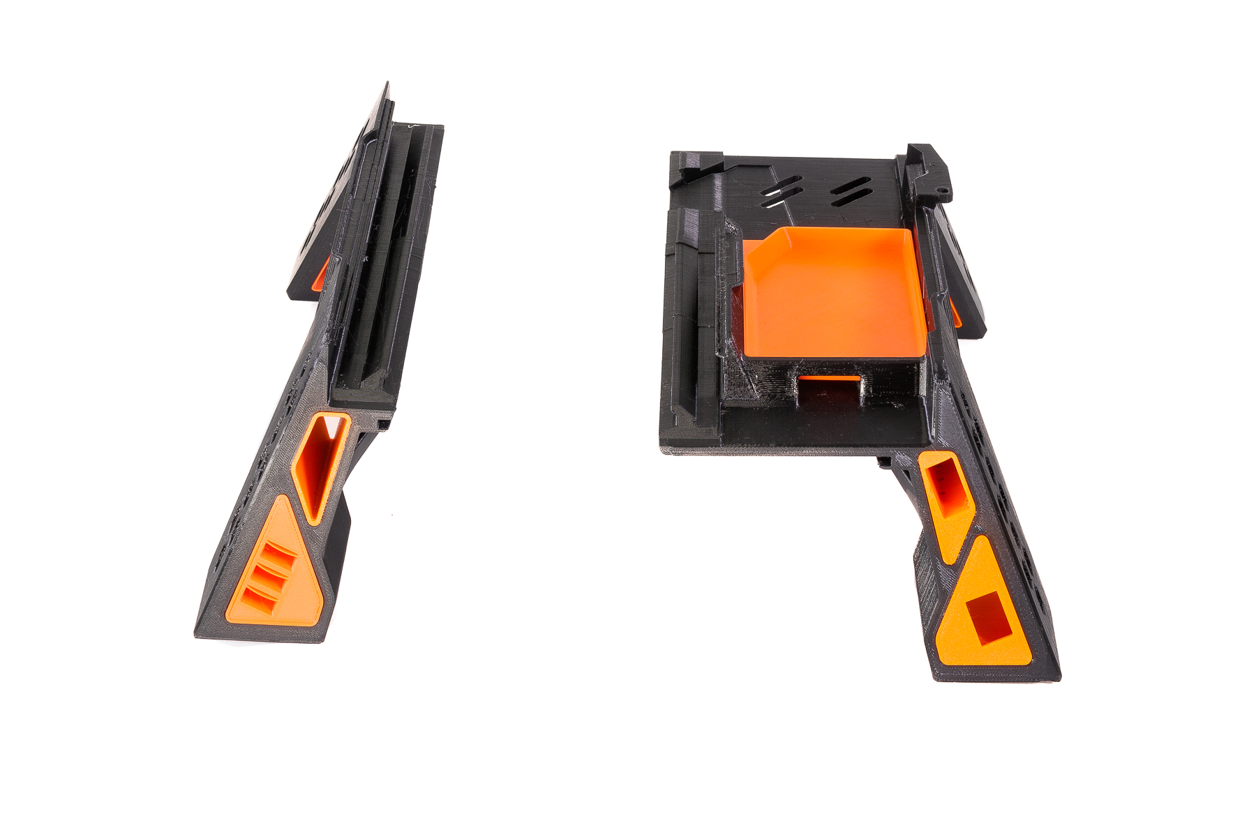
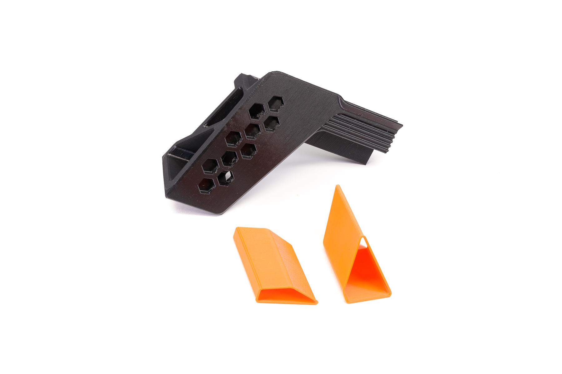
| Front left leg, you could use one of the inserts to hold three USB drives, the other two are just decorative. | The front right leg can hold a tool tray, the USB port and power switch relocated from the printer’s electronics box. |
 |
 |
| The rear left leg holds decorative inserts only. | The rear right leg, also just with decorative inserts (some cables will be threaded through the upper insert). |
 |
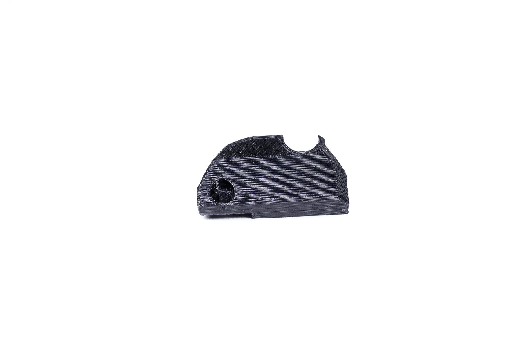 |
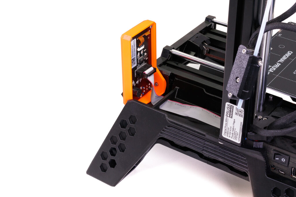
| Filament sensor holder. (optional for printers that have them) | New cable cover part (only for printers with the filament sensor). |
Optional printed parts checklist
(sorted approximately by their importance)
 |
 |
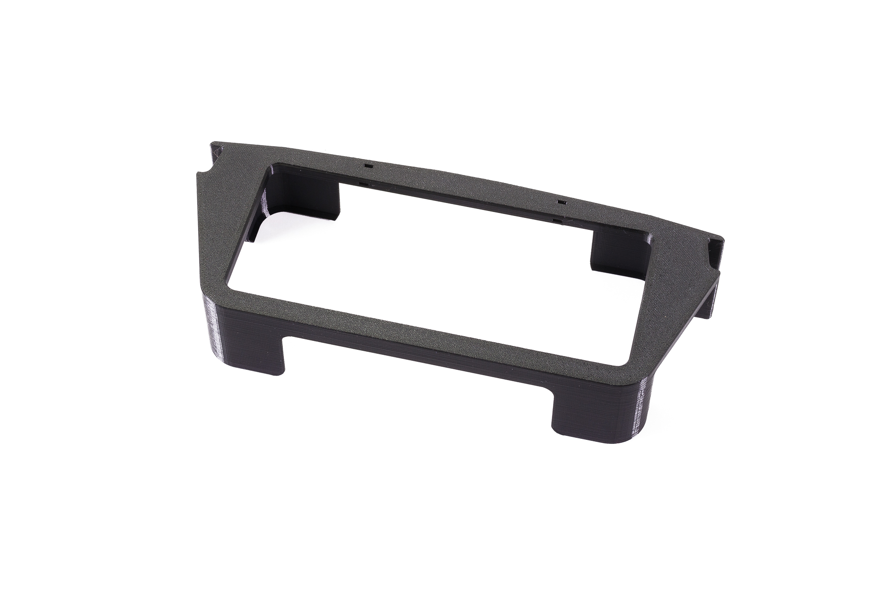
| PSU holder, for holding the PSU brick under the printer. There are two versions available (for the older version of the PSU as well). | Y-axis tool tray with a decorative strip. |
 |
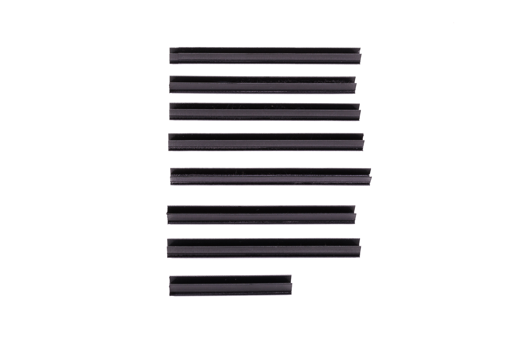 |
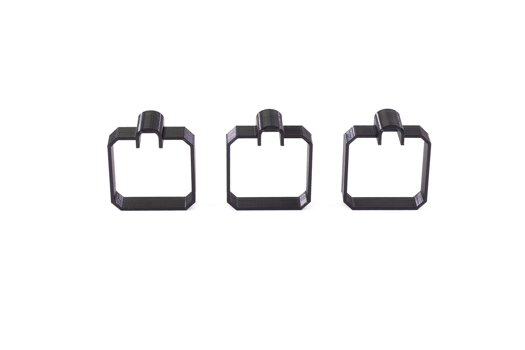
| Stepper motor cable covers, with little collars for a nicer attachment of the cables’ fabric sleeves. | Extrusions dust covers. You can press them into the cutouts in the axes extrusions. Not very important components, on the Z-axis they are just decorative, however, on the Y-axis, they might actually prevent debris from falling into the cutouts. |
 |
|
| Hexagonal inserts fit into holes in the legs. Their purpose is purely aesthetic, you can use as many as 40 of them or none at all. | |
Other Hardware & Fasteners
For placing the filament spool under the printer:
- 4x2x500mm PTFE tube – example at Amazon.com
For relocating the filament sensor:
- 2× M3x20 screws
- 3× zip ties
Optional (for relocating the power switch and USB port)
- 3× M3x30 screws
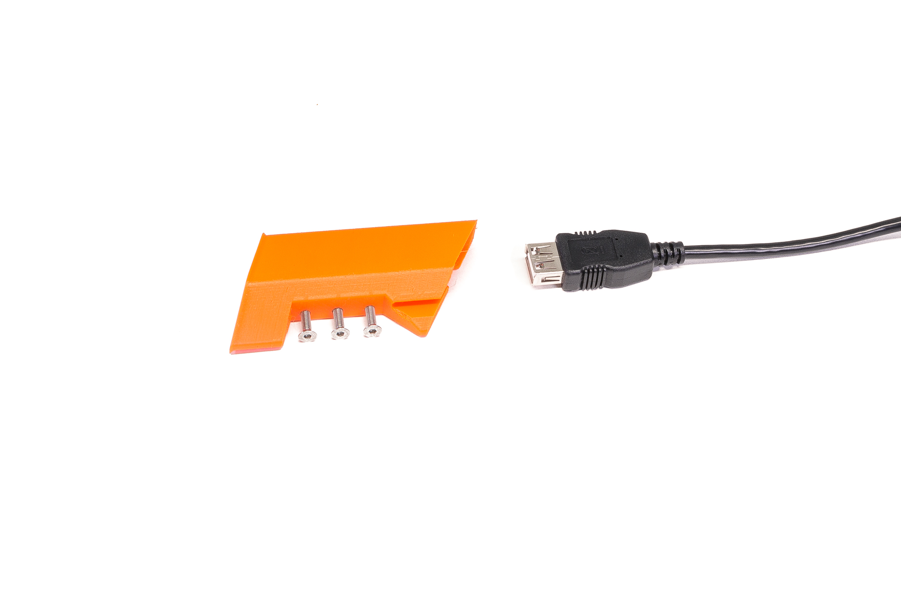
- 50cm USB extender, a 90° (right-angle) male and a female connector (note that there is some leeway, so a normal non-90°connector would work, too) – example at Amazon.com
- 50cm power cables (12-19 gauge) with Faston female connectors (blue or red size) – example 1 and example 2 at Amazon.com. Hopefully, you should find a lesser minimal quantity/length for sale, on the other hand, you will have plenty of surplus for other projects 🙂
Step by Step Assembly Instructions
We suggest combining reading the written instructions with watching the included video. If you mess up something and don’t know how to fix it (like, disconnecting a cable from the electronics by accident, etc.), you can check the MINI+ kit assembly guide.
Before you start, turn the printer off and disconnect the PSU cable!
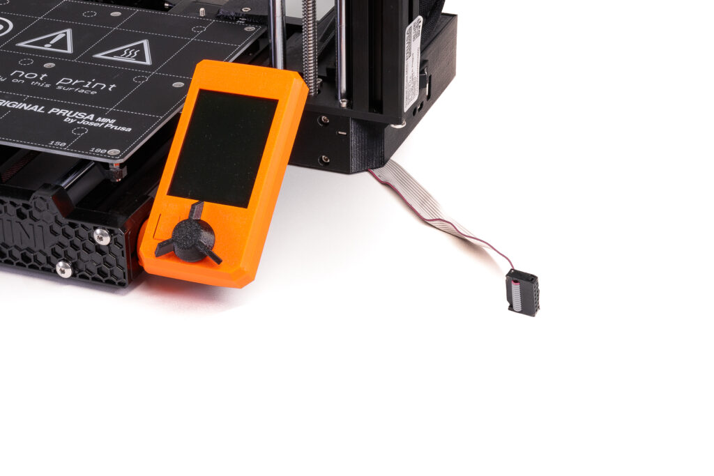
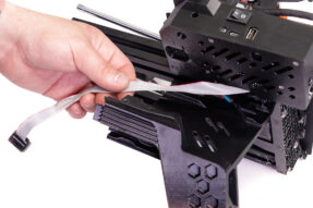
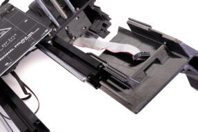
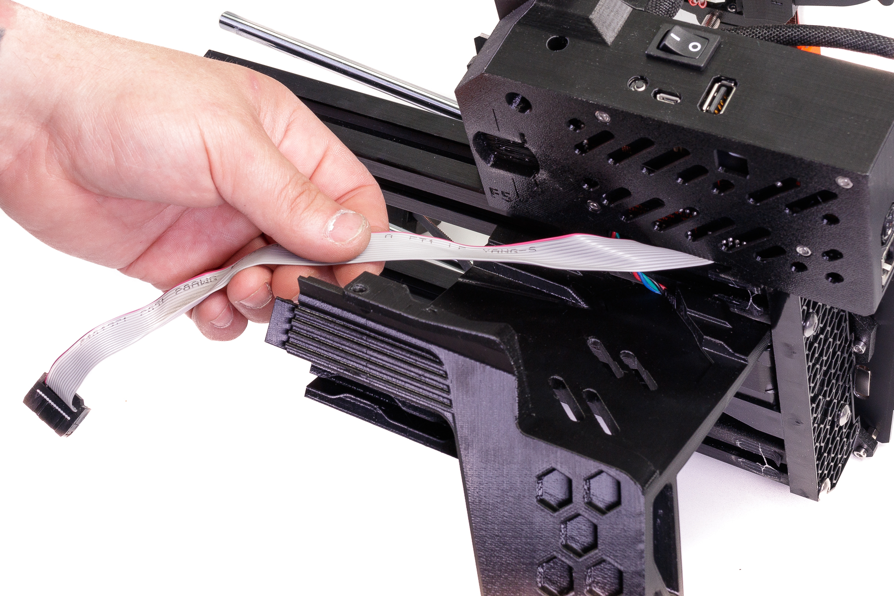
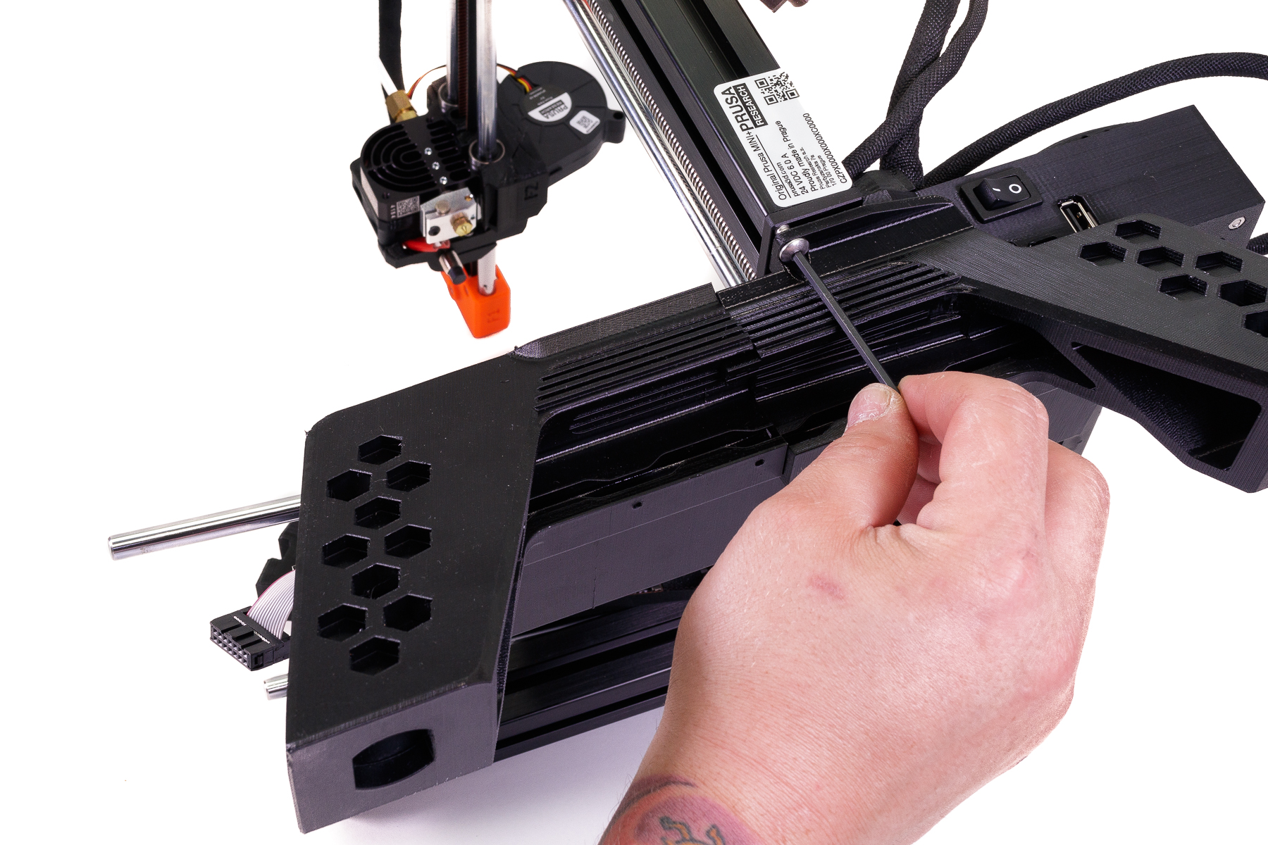
- First, carefully disconnect the display box cable.
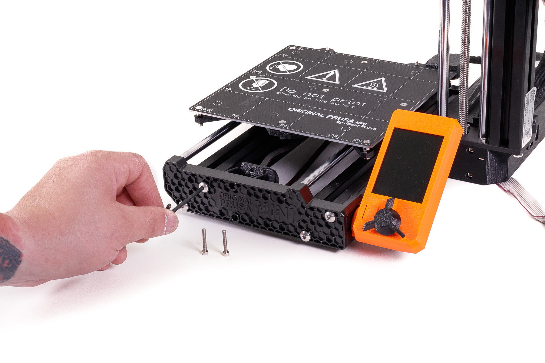
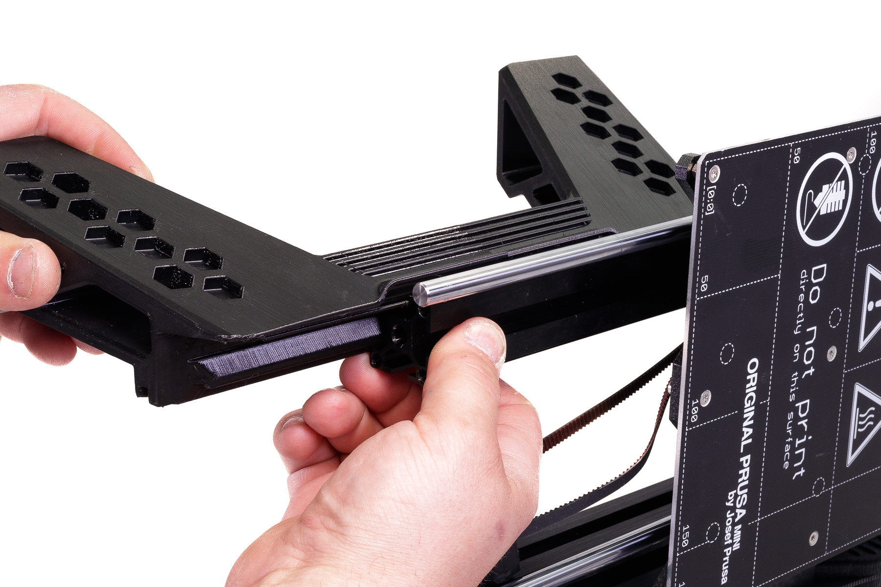
- Unscrew the front part of the Y-axis. There are four larger screws holding the part itself and two smaller screws holding the Y-belt idler. You will need 3mm and 2.5mm Allen keys.

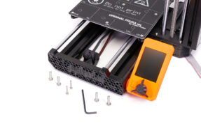
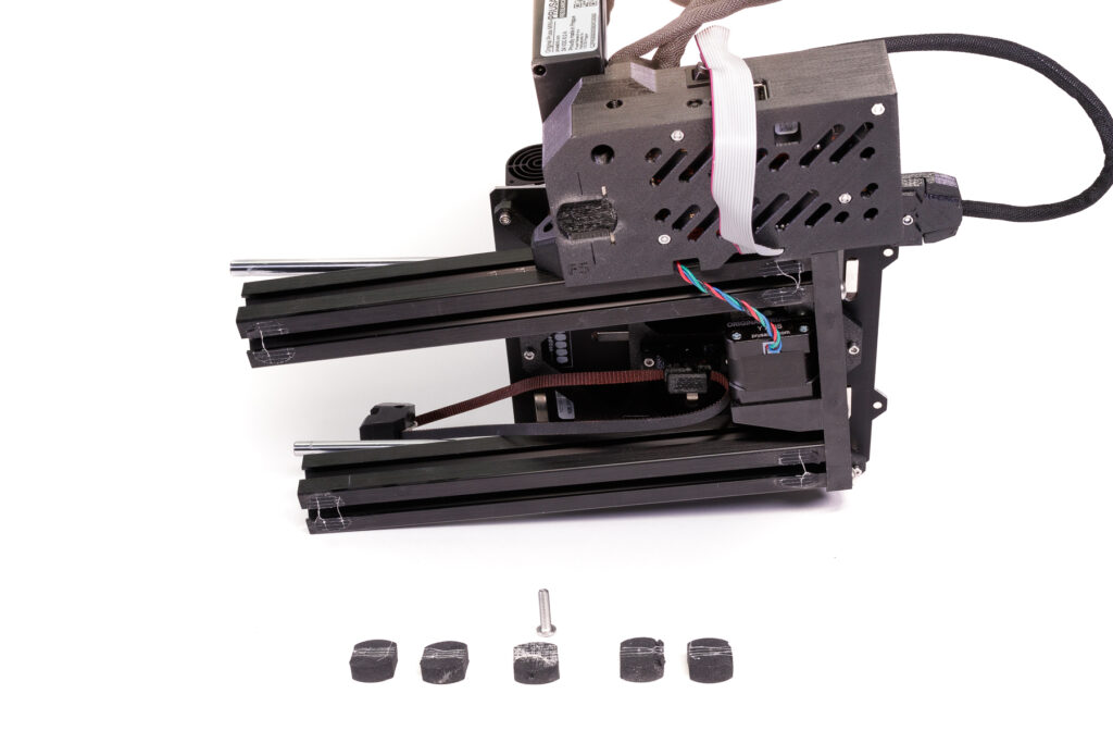
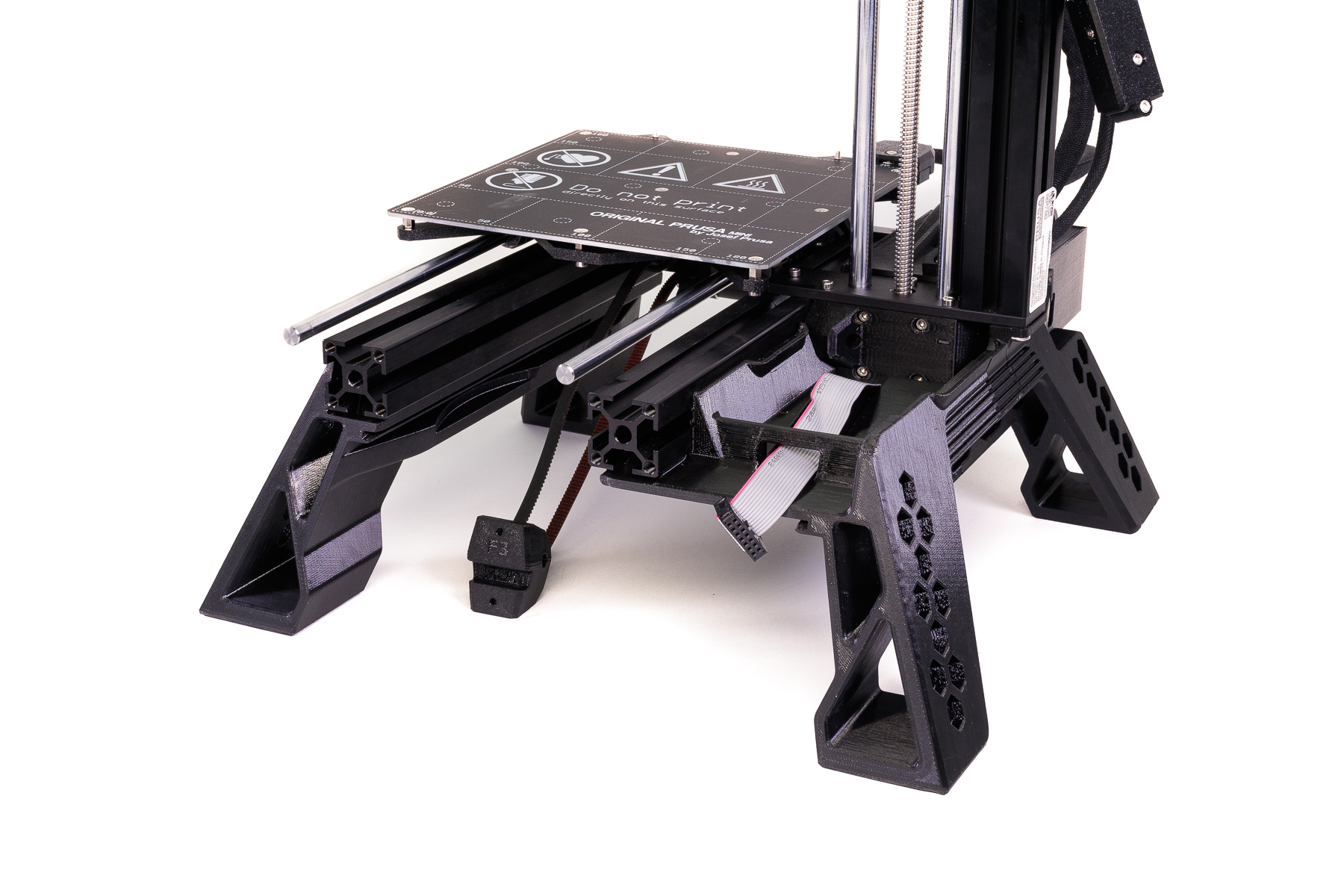
- Place the printer sideways and remove all the anti-vibration pads. Put them into cutouts in each MINI Base leg. Remove one screw from the bottom of the Z-axis extrusion.
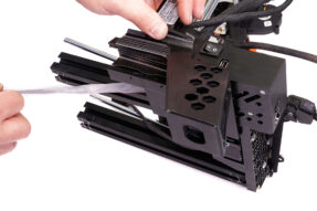
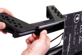
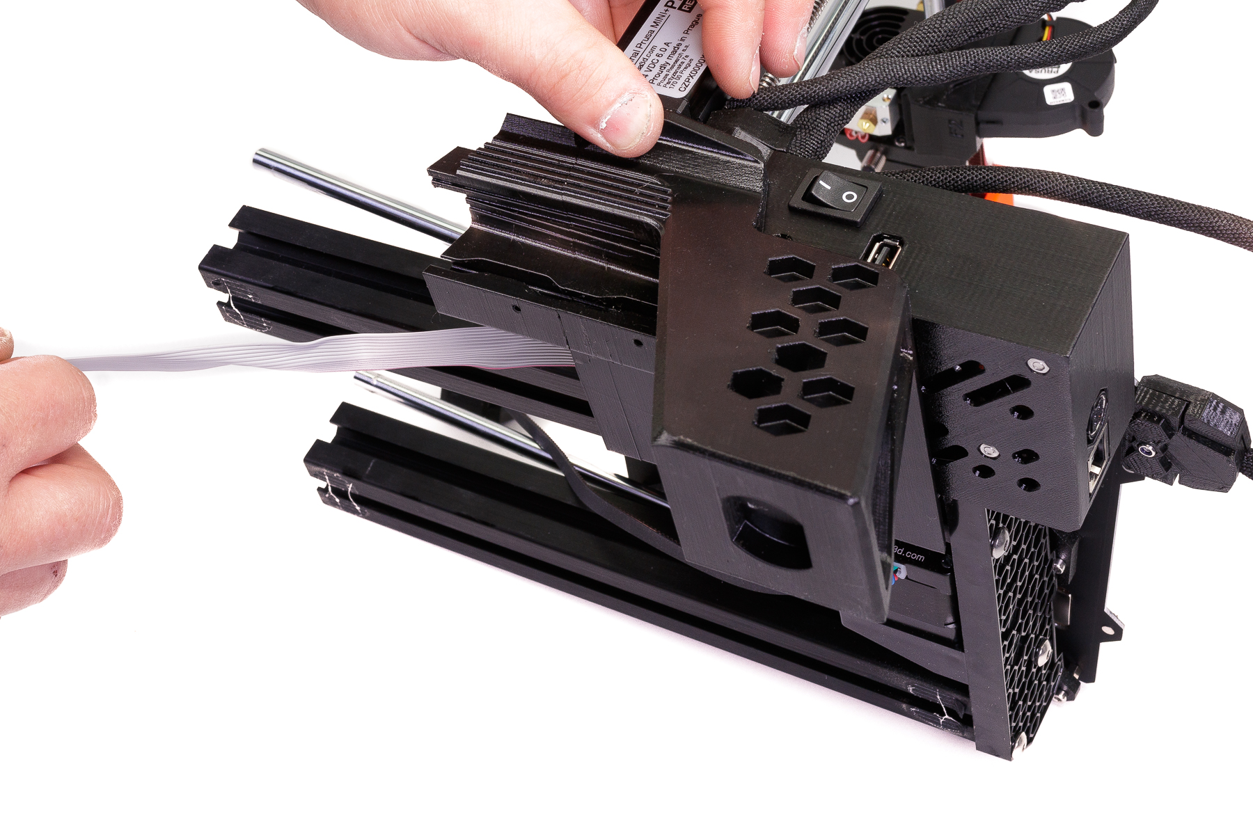
- Now, slide the rear right leg onto the right Y-axis extrusion. Before you do so, make sure you place the display box cable neatly into the corresponding groove on top of the RR leg, so it doesn’t get pinched.
Note: If you have any troubles sliding the leg onto the extrusion, you can use a slightly different approach, also shown in the video: remove the extrusion from the printer first, mount both legs separately and then return the whole assembly to the printer. - Continue with the front right leg. Secure both legs to the Z-axis extrusion (using the same screw you removed in step (3).

- Attach both front and rear left legs as well. No screw is needed to secure the parts on this side.
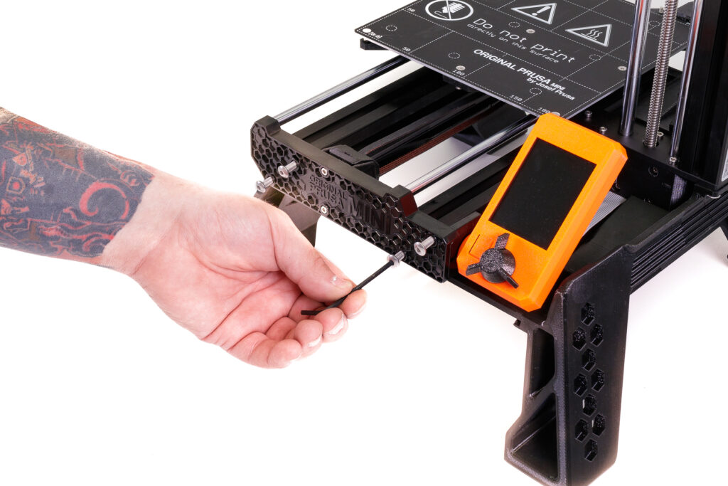
- Screw the front part of the Y-axis and the Y-axis idler back on.
- Reconnect the display box cable.
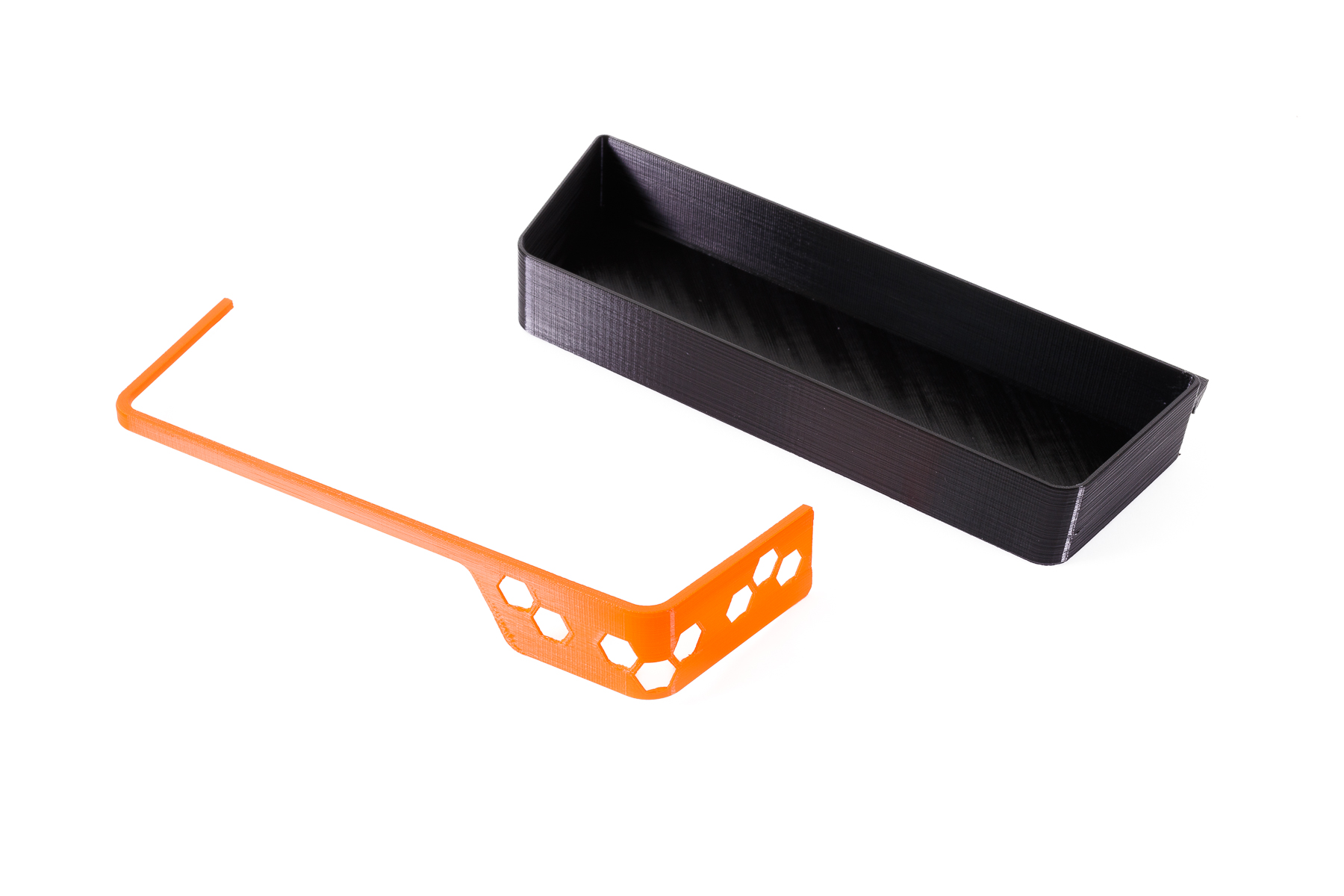
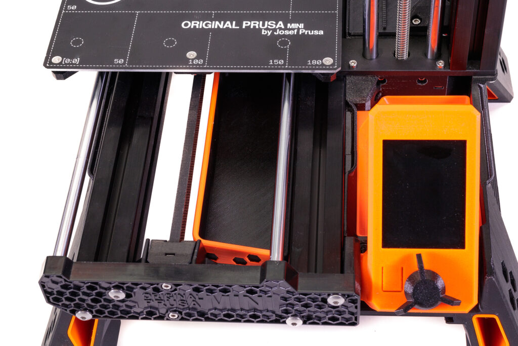
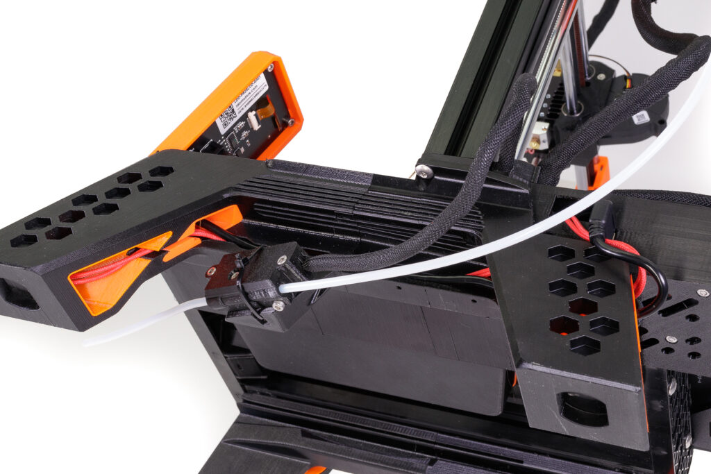
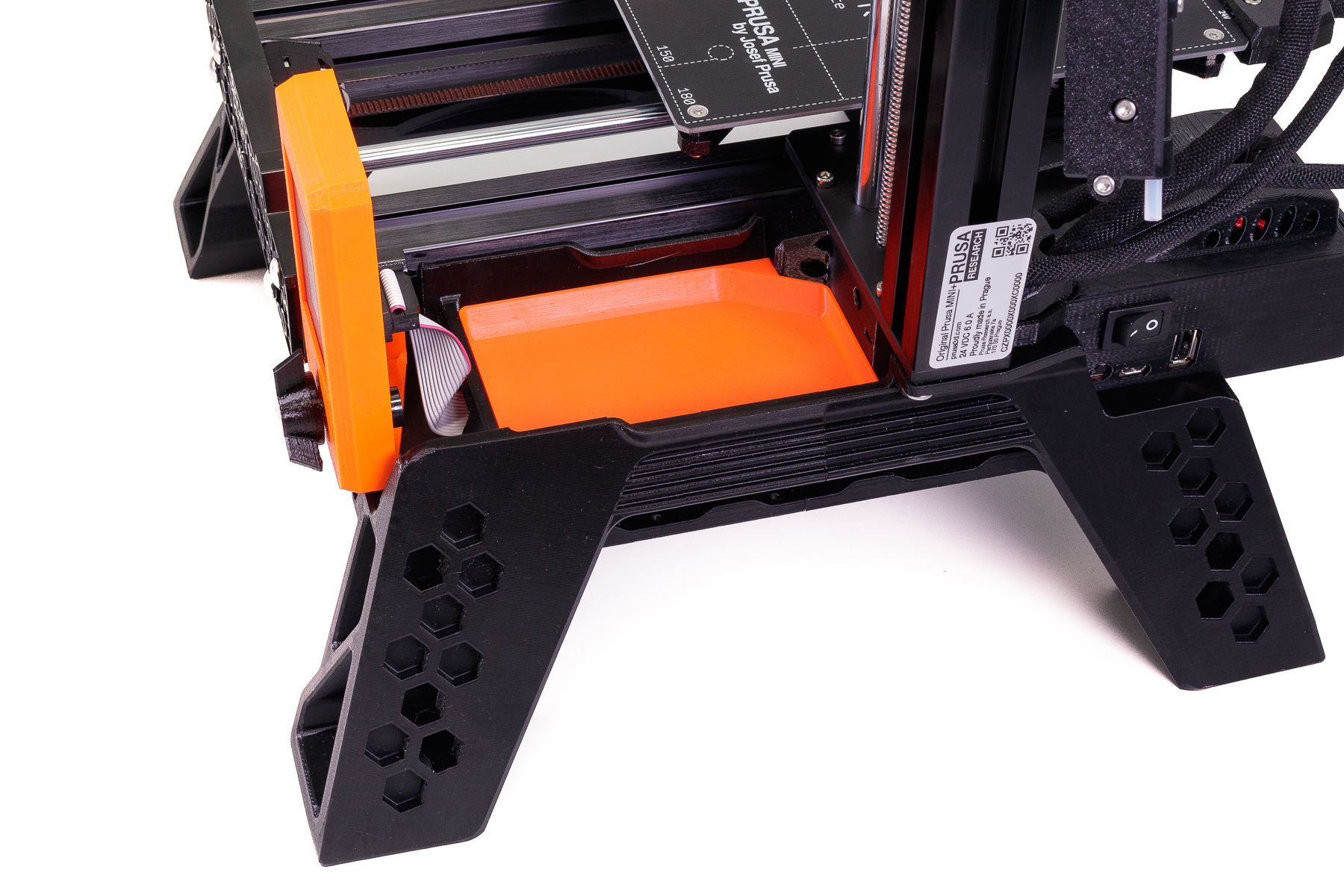
- There are two trays for storing tools. One is placed behind the display box and is accessible all the time, therefore it’s suitable for things you might need even during a print job.

- The other tray is placed under the heatbed and is more suitable for tools and parts you might not need that often (say, extra nozzles, lubricant, etc.).
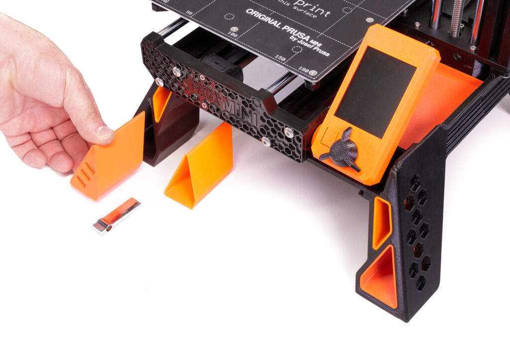
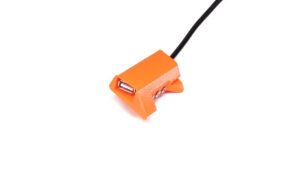
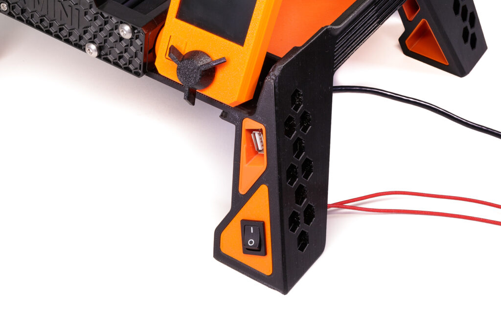
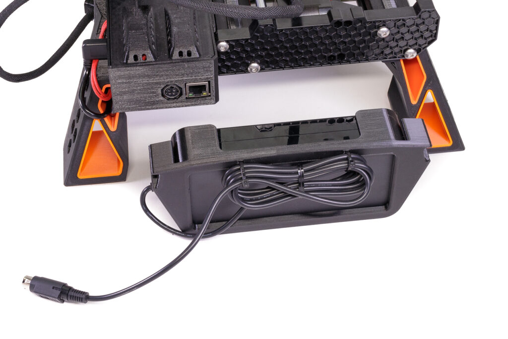
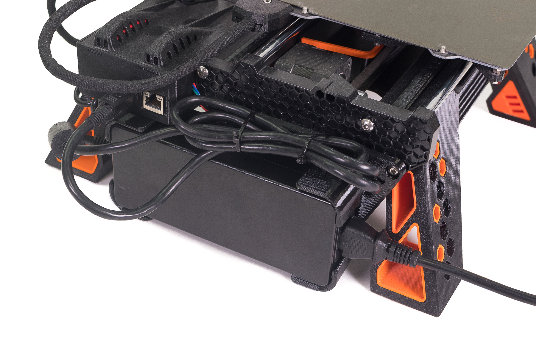
- The insert in the front left leg can be used to store extra USB drives. The insert in the front right leg can either be purely decorative (as on the photo), or it could house the power switch and the USB port:
Relocating the power switch and USB port
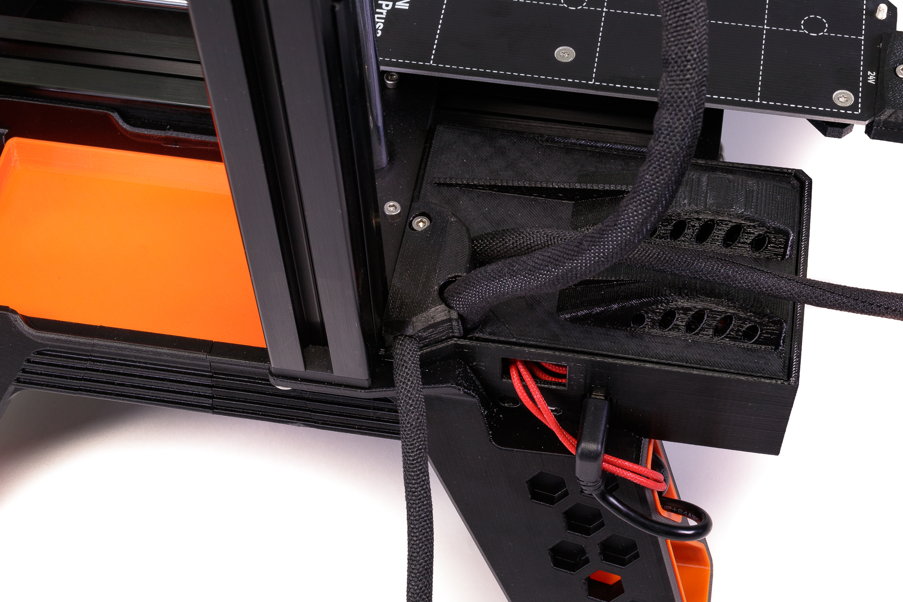
The following steps (12-15) are optional, you can leave the power switch and USB port where they are. However, it’s really convenient to relocate them to the front, so you don’t have to reach around to the back of the printer all the time. - Open the printer electronics box, disconnect and remove the power switch. You can use Chapter 5, Steps 8 and 9 of the MINI+ kit assembly guide for reference. There is a safety latch on the side of the switch – press it to remove the switch from the electronic box. Connect the new 50cm cable with Fastons into the Buddy board. Connect the USB extender to the USB port. Thread both cables through the upper insert in the rear right leg, like in the picture.
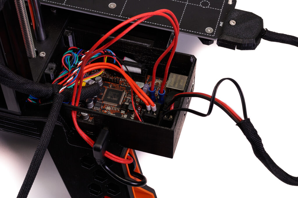
Note that in the video, we extend the power cable by soldering/heat shrinking, however, this is only necessary if you can’t find a cable long enough or want to reuse old cables for some reason. - Press both cables into the zig-zag groove and thread them all the way through the holes in the front right leg.

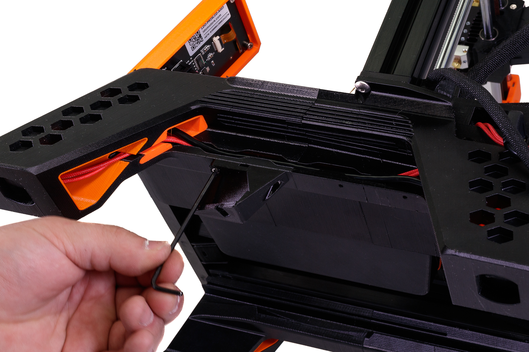
- Take the “female” end of the USB extender, put it into the upper front right leg insert (see the picture) and secure it with three M3x30 screws. Do not overtighten them, so you don’t pinch the cable too much or crack the printed part.

- Insert the power switch into the lower insert and connect to the Faston cable.
- Close the electronics box. If you use the filament sensor, use a new cable cover part, since the sensor cable will now lead under the printer, which leads us to the following step:
Relocating the filament sensor

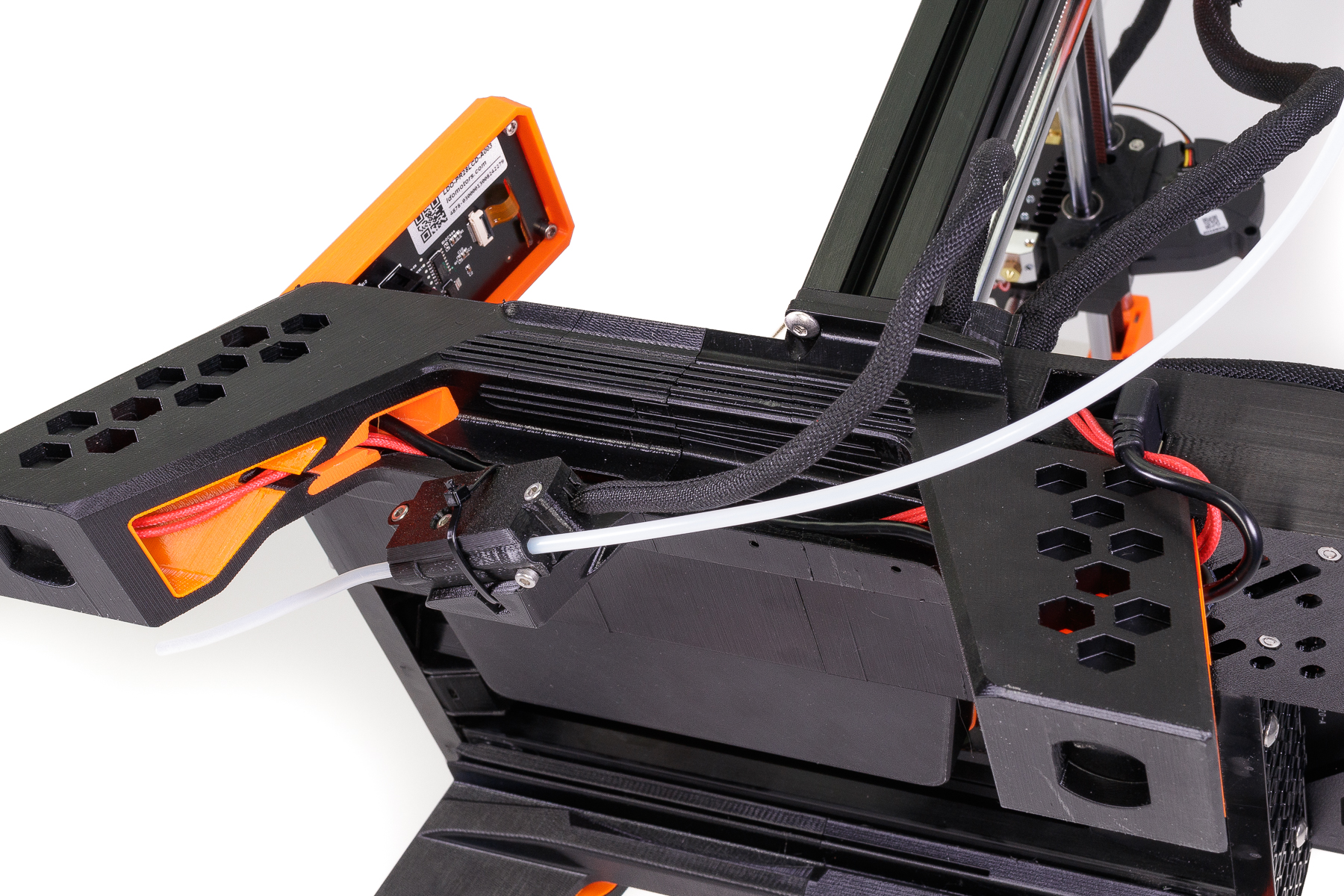
This step is rather mandatory because when you store the filament spool under the printer, the sensor in its original placement would hang there at a weird angle. If you don’t use the filament sensor, just replace the existing PTFE tube with the new long one and continue with step (19). - Attach the sensor holder to the bottom of the base using the two M3x20 screws. You can choose between a position near the front leg or the rear leg, it’s completely up to you.

- Insert the new long PTFE tube into the filament sensor. Place the sensor into the holder and secure it with a zip tie.
- Slide the filament spool onto grooves in the inside of the MINI Base legs. Make sure it turns freely.
- Insert the PSU brick into the holder and mount it onto the base from the rear side. If you have the older version of PSU, the holder is attached with screws to the rear side of the printer.


The alternative PSU
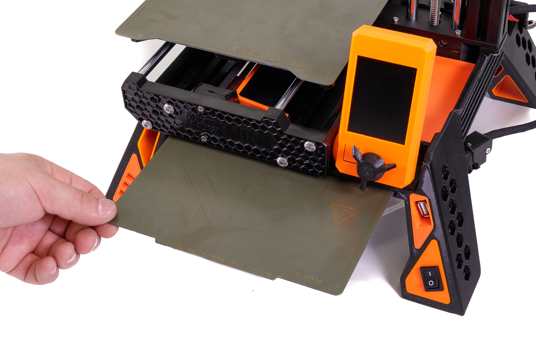
There is a slot for storing an extra print sheet.
It’s Operational!
Well, almost. Before printing again, make sure you run the printer calibration, just in case (when partially disassembling the Y-axis, the printer geometry might have changed slightly).
That is it! We are eagerly awaiting to see what you all come up with to make the MINI Base your own, different color combinations, new improvements, additional mods, all come with loads of potential.
Enjoy your MINI Base and as always,
Happy Printing!
– David Schwarz, Vlado Turek, Vladimir Kafka
This is really cool. Not sure how freely the spool will be able to spin to feed filament though. Especially heavier spools.
its designed for prusament and have no problem with that
I have 2 minis with this mod that have been running for 3 months or so. Everything works great, but the filament reels sometimes get tangled. This doesn’t happen when I put the filament on the rollers a foot away from the printer.
I suspect that having the reel so close to the extruder, and having the filament rotate into it, causes some slack.
I actually think it tangles because there is less slack than on the free-spinning roller. At least that’s what I’ve seen with a brand of high quality but not neatly rolled filament and this base. With more slack on a roller, the filament can hang a little and get loose from the other strands.
I observed the same problem with prusament. It seems the fillament get stuck because it gets too tightly rolled. One strand of filament gets caught under another and it gets stuck. Did you find any fix for this?
What about those of us who only have the Mini+ how do we get around printing the RF?
They all fit. It’s just badly worded. All parts except the RF don’t need supports
Sorry, I have changed the word order of that sentence now.
RR feed needs also supports…
Agreed.. Right Rear leg needs supports too
I had to add supports for the RR leg because the G-code file that loads from the site doesn’t work well with my setup. I’m not sure what my issue is, but the base of the supports were just not stable on my printer. So I loaded the STl file into PrusaSlicer and added extra supports down low. I found that it printed fine with supporting the part all the way up (as seemed to be the case with the saved G-code on the site). By providing more support down low the upper layers did just fine building on the natural angle of the part.
All stl´s have now optimalized orientation adn those right legs g-codes have supports on build plate. I apologize for that mistake.
> No supports are needed, with the exception of one component, the right front (RF) leg.
You might want to update the description if both right legs need support (from the buildplate only?)
Are all the parts also printable with the 0.6 mm nozzle? Or do you need the higher resolution of the 0.4 mm nozzle to make the parts fit well enough?
parts may not fit
“May not”, or “will not”? I’m half way through the job with the right legs to go, printed with the 0.6 nozzle, and I just got worried it won’t fit…
Amazon Basics spools are usually a bit wider, do they also fit and rotate free enough or do we need longer legs for this?
Holy cow! I do not have one of the new MINI+ printers; I have the “original” Prusa MINI. 🙂
This set of items should still work, though, yes?
And as above, my concern is the rotation of the spools. I have started using AMZ3D spools from Amazon; they measure about 19.8 cm across and about 6.8 cm wide. I’d be moving from your vertical “original” ball-bearing wheels to a horizontal alignment rubbing on plastic. Hmmmm ………
It works on any MINI or MINI+ just the same.
Id like to see a BoM for this, so i can be prepared before starting this print.
Why not add a “lazy susan” plate for the filament spool, using a bearing from spool rack? This (I think) will make the filament spool rotate easier with lesser friction.
did this just put the spool on a figit spinner..works with smaller spools too
Where do you get the little rubber feet?
from bottom of printer
I viewed the supplied G-codes in the G-code viewer for RR & RF. They both include support.
The article states “Of course, all parts are designed to be easily printable on the Original Prusa MINI+ itself. No supports are needed, with the exception of one component, the right front (RF) leg.
It should state “with the exception of two components, the right front (RF) leg and the right rear (RR) leg.
You are absolutely right!
The Y-axis bed also clearly needs supports. Looking at the uploaded gcode several parts have supports.
Y-axis tray, I meant.
All stl´s have now optimalized orientation adn those right legs g-codes have supports on build plate. I apologize for that mistake.
Please re-think the NO Supports needed statement. RR certainly won‘t work this way. Visible after 5 hours of printing….
https://media.prusaprinters.org/media/comment_images/2a/8e92f0-c27f-4c9d-8e32-93ddb2ad49d4/thumbs/cover/1280×960/jpeg/59edcf7b-a39e-4adb-ada2-8d9b6db64477.jpeg
All stl´s have now optimalized orientation adn those right legs g-codes have supports on build plate. I apologize for that mistake.
But you still state that the RF is the only thing that needs support in the description. I’m printing this stuff for a friend on my MK3S and can’t use your gcode. You really need to correct the description
The g-code is only made for the prusa mini (+) right?
Man, this guy is freely giving this to the community. Cut him some slack jack!
This is absolutely gorgeous! Looks slick and seems super functional.
What about wider spool?
Mod for Raspberry + octopi-camera would be perfect.
yes, definitely – that was also my first idea when I saw the video
There are already other mods for the display, RPi+OctoPi, etc. Just look around the website. I grabbed a back for the display.
All parts printed. Now for assembly and photos.
RAH
This looks so cool, but will it make the Mini too tall for a Lack enclosure?
I would like to know this as well. How much taller does this make the printer overall?
I measured one leg in my CAD-program and it seems to add almost 12cm to the printer’s height. It would be nice if someone who has already modded his printer could measure the total height after modding. I am also concerned about the printer no longer fitting into my cupboard.
My Mini+ in a lack v2 cabinet has about 5 inches of clearance, which google tells me is 12.7 cm
So it’s gonna be close
It seems to only add around 9cm to the hight, so it should be fine for my enclosure. I might give it a try 🙂
I went ahead and assembled it into my lack enclosure. Does NOT fit. I modeled up some temporary 1.5″ shims to raise the enclosure to allow it to fit. I will improve the design design of the shim this week and then upload it to thingi and Prusa.
Yes, it makes the Mini+ too tall for the Prusa version of the Lack enclosure. I just assembled the base the total height of the Mini+ is now 470mm. The total internal clearance in my Lack enclosure is 447mm . . . 23mm too short.
I am printing extended corner brackets to raise the enclosure by 35mm but of course now I’ll have to order taller plexi-glass panels . . .
How is the holder for the older-style PSU printable on the MINI+? I’ve been unable to fit it into the build-volume in an orientation that makes it printable.
Thanks!
second this – any ideas ?
I managed to print the part as is on the MINI+ without having to cut it into multiple pieces. https://ibb.co/FxbVksq shows how I was able to fit it. Not particularly practical, but it worked out alright for a one-off.
I could not get the part to slice in Cura, however it sliced just fine in Prusa’s slicer.
I have 2 questions.
1 how does this effect the background noise of the printer vs being placed on a concrete paver?
2 wouldnt the spool try to move around on you? Wouldnt having it sit on a lazy-susan be more “assistive” to the feeding of the printer?
Cable Management and Rear Right leg also need supports
I would really like if you could post CAD files. I imagine allot of enthusiasts would love to modify this awesome design.
Before I go ahead and spend the time printing this only to find out it no longer fits on the shelf the Prusa Mini+ currently sits on. Could anyone please be so kind as to post a set of dimensions (total width x depth x height) of the printer once the mini-base is attached?
Imported the STLs to Sketchup and ‘assembled’ them. The footprint is 325mm x 325mm. The height added is, I think, 90mm.
I´m trying to find any info of the footprint of this kit.
How is that even possible when the measurements on prusas website are 38×33×38 cm; 15×13×15 in (X×Y×Z)?
I´m just desperate to find that footprint haha.
Two questions;
How do I know what PDU I have. I’m the United States. Purchased in January 2021 and received in March.
How many spools does this take?
Same Question here. How to figure out which Power supply i own. I ordered the mini and get an update on the mini+ on delivery, located in Europe. Is it the new or the old Power supply?
I asked in the comments where the STLs are hosted as well, and got the following answer:
old is longer then new one. old have 6,7″ new have 6,5″
I’m curious as to why Prusa don’t recommend PLA. Is it a color matching thing? A finish thing? A hatred of PLA thing? 😉
Is it possible to print all the black parts with one spool or does it require more?
I’ve got black PLA and orange PETG available, but I’ve never had a successful print with PETG….guess it’s time to contact tech support to figure out why.
Prusa doesn’t recommend PLA because PLA in general is problematic for technical prints. It is not just its low temperature resistance, which might not be an acute problem for that specific print but its safer to have a bit more heat resistance close to a heating bed in any case. The other thing is that PLA gets more brittle with time due to moisture mediated hydrolysis. The reason why PLA filament tips can get easily breakable when lying around unprotected for a long time. Connected to that is PLAs very poor impact resistance, even if it is brand new and when it breaks it tends to snap apart suddenly or even violently. A printer base will be subject to a lot of vibrations, you’d rather want a material that is good at handling those for a long time. You are much better of with PETG for example for such prints.
That said, if you insist, PLA might just work too, the base seems to be designed fairly robustly but I would not recommend it either.
Any reason to avoid ASA or ABS?
It could be that PETG warps less than ASA/ABS. The parts may not fit if they are warped.
This looks like a good upgrade, however I’m really tight for space on my windowsill – can someone post the size of the new footprint for me to check it, before I start printing parts!
Don’t worry, I found it in a previous reply above.
Any recommendations for getting that PTFE tube in Europe (Switzerland)?
i’ve got mine from the 3dware online shop:
https://www.3dware.ch/PTFE-Tube-2mm-inner-and-4mm-outer-diameter-En.htm
what is the v7 for?
Hello,
I want to print less parts per batch. I got the 3d models and all specs but not the % infill.
Can you help out?
Anybody else get halfway through assembly and think: « if this was a good idea, they’d ship it from the factory this way. What a nightmare. Ill fitting parts and cross threaded screws. What did I do to deserve this fun?
The M3x20 screws to fit the sensor holder seem to be way too long. They screw through the cable guide and deep into the part (where I expected holes for these long screws, but there don’t seem to be any), breaking it along the way.
Since I didn’t start with a kit I also had to figure out how to replace the tube from the extruder part. It’d be nice if this could be explained.
M3x6 seem to work a lot better?
I came here to say almost exactly this. Only I didn’t end up breaking my parts. I used M3 x 8MM and they worked perfectly. I also have noticed that the left front leg will come off easily. I would like to suggest to the designer that they make a change that will allow using screws and t-nuts to hold both pieces together and firmly attached to the extrusion.
I agree. I have a printed handle on the Z-axis extruded part and if I pick up the printer that way both left legs fall off. It appears stable enough while sitting the bench printing, but moving the printer usually results in needing to reattach the left legs.
For those saying the left legs are falling off, you need to watch the video to see the proper assembly of the left legs. They slide into the metal frame extrusion precisely and once in, will NOT come off. Of course, I learned this the hard way to, but just trying to install the left legs AFTER everything was re-assembled and screwed back in. That won’t work. I now have this print, AND my PETG printing technique perfected to a T! It is amazing!
I slid my left legs in from the end of the aluminum extrusion, and it seemed to fit very intentionally and firmly into place. It did take a bit of careful examination to get it started though. Once is slid in all the way, it felt secure. HOWEVER, later on when handling the entire unit I applied too much torque and the front left leg popped back out (the back left leg did not). The only way I could get the front left leg back in was to again remove the front plate and idler and slide it in again. For this reason, I would argue that the engagement between the left side printed legs and the aluminum extrusion needs just a bit more refinement on the design.
I don’t know why they indicate to use M3x20, but if you look at the picture of the filament sensor you can see two bolts which are more like M3x6 or M3x8 in dimension.
I agree. Anything longer than 6 mm or maybe 8 mm will stab the cables in the zig-zag slot. The instructions need to be updated.
I ended up using M3X6 “PT screws” which are self-tapping into plastic. The machine screw threads have only minimum engagement into the plastic, so I chose the PT screws as they are of course more aggressive.
I have just assembled mine today and found all the parts fit really well, most of the filament spools seem to fit ok except the Geeetech which is too small in diameter so in future I will be ordering filament that fits better, I also found the prusament PETG is a wider spool, I Have a beer mat under each leg at the moment going forwards I will make a shim to go under the rubber feet to make them stick out a bit more.. All in all it is an excellent idea and well designed, it reduces the footprint on my desk quite considerably. I printed all the parts at 20% infill in PETG and the printer is quite sturdy.
Just reading some of the other comments, I used 3mm x 8mm screws in the sensor holder and after stripping down my extruder I found that the PTFE Tube to be just a push fit, I did find the extruder dirty on the inside though and took the opportunity to give it a good clean.
https://google.com/
K
Prusa staff, another one to delete.
The tray that fits behind the screen looks like a perfect space for a raspberry pi…Anyone able to make that a reality? 😛
Has anyone had any issues with bed level since doing/adding this mod? I’m getting crazy Z variation on my 1st layer calibration- especially at the end rectangle- 1st 1/4 is perfect (as are my lines getting to this point) but then 2/4 light z, 3rd heavy, 4th quarter light. I’m at a loss on this. About ready to go back to stock! I’ve checked all nuts and bolts, cleaned the head, the plate, re-run the wizard, and same results. Anybody have any suggestions?
Curious if you ever managed to fix it or had to revert back to stock. I’m having the same problem after just assembling mine.
Prusa provides a great article for “squaring” the Mini/Mini+ at the following link: https://help.prusa3d.com/article/squaring-your-mini_158518
After the Mini Base upgrade, I next performed the steps to check/correct the printers squaring and found it needed to adjust the XZ axis (it was much lower on the left compared to the right side of the print sheet).
After verifying the mechanical alignment, I performed a Factory Reset of the firmware followed by performing First Layer Calibration for each of my three print sheets from scratch.
For me, this was a winning combination.
Attempting the Original Mini+ Base: I have had 3 unsuccessful attempts to print the leg components, but the print job fails in mid-print, When I return to printer, the nozzle is stuck to the incomplete part and control screen is filled with random numbers with no option but to shut down and restart from scratch. I am using brand new, freshly opened Prusament PETG at the heart of recommended nozzle (250) and bed (85) temp settings. Is the sticking nozzle because of wrong nozzle temps causing the fault? Or is there a program error making it stop (and the sticking/temp is not the cause?) I am wasteing a lot of PETG. Please help.
Got it installed today, 15% infill and 0.3mm on Jet Black PETG! Really cool space management, love it. I also put supports for RF Leg,it felt a bit risky to print it with any support at all… I have one complain only, the screw for fixing RR leg to the vertical aluminium profile… so much suffering to get it through smoothly :E. Cheers!
Yeah man, me too 😅
Does it fit inside an IKEA LACK table enclosure ? Anyone tried ?
Thanks
I don’t have the Lack Table yet (is on order with Ikea and waiting for it). I was planning to put it in it but alas after measuring and according to the Ikea spec, it’s too high for the Lack Table. It is almost 47cm high. The Lack is 45cm top to bottom. Very disappointing. It’s such great design.
People that have installed the Mini/Mini+ in a Lack enclosure used the LACK V2. It is taller. Just follow those instructions. It is CLEARLY too short for the LACK V1 enclosure and the Plexi panels are too short.
If you must use the Lack V1 and don’t want the “enclosure” part you can just extend the legs by a few cm. There are many options for extending the legs on Prusa/Thingiverse
My 2 cents.
I had some issues with installing the right rear leg, because of the y-axes cable.
Yes, same here. But I eventually got the rear leg attached. But then the right rear and right front leg simply do not fit flush together. I am deeply disappointed and wondering where I can find more sticky pads for the feet to put my printer back to normal.
Great design. Thank you. Makes the Prusa Mini+ MAGESTIC.
Quick note: Having a problem with the length of the PTFE tube. It seems that it is dragging the filament especially when using the sensor. As a result, the extruder starts slipping? Anyone having this problem? When I do not use the long PTFE tube ( with the Reel under the Mini+)and put the filament reel back in it’s original base, everything works.
The design makes the overall height of the Mini approximately 47cm high, which is higher that the Lack table (45cm) which makes it that you cannot enclose it in the great Lack table enclosure design. Any ideas anyone?
Just a thought that I had, if I am thinking of the right Lack Table Design then you are going to include glass/acrylic panels around it with a door? If so then you’ll need to 3D print some hinges for those doors. Surely those will raise the height enough for you for those extra centimeters.
If not, then you could 3D print some standoffs that would raise it up higher. If you went with a black table you could use some orange as accent pieces so that it matches your 3D printer.
I don’t have the tables yet but this will most likely be my game plan when I get around to it.
Thanks Jonathan, sounds great. Will stay in touch and update once I get things going in the very near future.
Hi what is the minimum length the USB extension can be?
The one linked in the parts list is out of stock and i can’t find any others that are 50 cm long only 30 cm.
Hi, what is the new height of the mini+ prusa with the base? im printing the enclosure v2 (mmu version). There is a space for 510 mm and will go next for the base. The prusa is about 400 mm and the base about 100 mm is that correct? I think that should fit right or do need to extend the enclosure a bit. Would like to buy the plexiglass/ acryl sheet next… Thanks for answer in advance
Loving the stand, looks amazing.
I have knocked up a quick power switch blanking panel that i thought would be good for filling the hole left behind after relocating the switch if anyone is looking for one.
https://www.prusaprinters.org/prints/70625-prusa-mini-switch-blanking-panel
https://www.prusaprinters.org/prints/70627-prusa-mini-switch-blanking-panel
Having a lot of problems screwing the Z axis screw back. There is no room for the screw to go in straight and gets stuck half way. Anyone with the same issue?
I could eventually. In case anyone faces the same issue, I first got the screw through the base leg hole, 1 cm out or so, then you can aim straight to the Z-axis by pushing the leg and start screwing slowly with the short end of the allen key as the longer one collides with the leg and doesnt let you do it properly. With some patience you will push the leg into its spot.
Also, while assembling the base be careful not to let the print bed slide out, some bearings could get out of its housing.
Had this exact issue and stripped two bolts out.
Just looked at this platform. I have the “old” powersupply.
It seems thhe holder for the old PSU can´t be printed on the Prusa Mini, which would be a shame for all not having a larger printer available. But perhaps I´m wrong?
It can be printed, I did it. Just need to print it at an angle with lots of supports.
It can be done. Like someone else posted, angle one side up and put supports under it. I have an Ender 3 also, so I just printed it on that. Mini printed everything except the power supply holder, Y-Axis tray and RF leg. It would have printed everything though, I just wanted to crank it out quicker.
I know that this comment is old, but in case someone else needs it, I was able to print the new PSU holder without supports.
Here is what I did:
1. Disabled the skirt. Print Settings -> Skirt and brim -> Loops (minimum) -> Set this to 0.
2. Make sure your brim is enabled. (So the printer can still prime itself)
3. Reduce brim width. Print Settings -> Skirt and brim -> Brim Width -> Adjust this number in increments of 0.5 until you find something that works. (I was able to get away with 1.5 mm with a 0.4 mm nozzle and 0.15 mm layer height)
You should now be able to print this out in the orientation that the STL file has by default.
Hopefully this helps anyone trying to print the new PSU holder.
Huge mistake printing this and trying to put it together. The legs fit poorly into the extresuions. The bolt that goes into the x axis was nearly impossible to get in and I stripped out two. Trying to get the front back on result in me breaking off the display.
I am not saying it’s a bad project, I just would avoid it unless you are willing to get really angry and just break your mini in the end.
If the legs “fit poorly” then there is a good chance they are not inserted correctly. I printed mine in Paramount 3D PETG on the Mini using Prusament PETG profiles. When I was putting it together, I had that issue with the legs falling off mine until someone pointed out they weren’t inserted correctly. Once I slid them in the extrusion properly, they are super tight and take maximum effort to to take off
Bringing in some of the parts (Insert Leg Hexagon for example) into the prusaslicer covers almost the whole print surface of the mini. Other parts come in just fine. Does anyone know what is causing this large size increase in the model files?
Just finished mine up and assembled. Printed everything on Mini except power supply case, RF leg and Y-Axis tray. The tray does require supports. Assembly of the right side was a little tough, but not too bad. I use a top mount spool holder also, so have some space underneath now. Thanks for the design!
The Amazon link provided for PTFE tubing appears that it may actually be PFA tubing and that the supplier is pulling a switcheroo. May want to recommend someone more reputable (which might mean avoiding Amazon entirely)
Ok, so now that i have tried building this, gotta echo the concerns of others in this thread. This is not a good design, and a complete waste of almost a full spool of filament.
So what happens with the Y Axis motor cables? In the first picture they are where they are on my printer, but in the way of the leg, In the second picture they are out od the way, but I have no idea how they get back into the electronics box.
Did anyone else have issues returning the screw to the Z-axis??
That was the ONE hiccup for me for the entire process.
So much so, however, that I almost tossed the base prints in the garbage. I had to use the calming exercises my therapist just gave me. Lol. Dang!
Interested to know at post processing work was done on the parts in photos above?
PETG and me are not good friends.
I used supports (of my own configuration in Prusa Slicer with the STL files) when printing both the RF & RR legs. Basically, supports are only needed in one obvious area of the RR leg and then on the center part of the RF leg, just FYI. Next, who spec’d the M3x30 screws for the USB port? How are you supposed to fit a 30mm screw to secure the USB extender. Not possible. Downsized to M3x10 for that section and worked great. Could possilby even use M3x16 there as well. I’ve been at the printing for nearly a week now. It’s been a lesson in PETG printing mostly. Ugh! However… learning! Hopefully the build goes well!
I have mastered & perfected the printing of this base! I’ve printed it about 3 times now. Yes, I get obsessed with things like this until I get it perfect. I am a perfectionist. The best print for me was with the Prusament Jet Black PETG material printed at 60mm/s, 230c Nozzle temp, 70c heatbed temp with 0 print fan running on the Mini+. I live in Colorado (near Denver) in the US, so, a pretty dry climate here. This base rocks! That is all… Hit me up with any questions you may have and Happy Printing!
Did you do it with 0.15 mm layer height? Have you tried 0.2?
Anybody have slightly poorer print quality after installing the Mini Base? I really love the look and function of this base, but I did notice that the right side sags ever so slightly and introduces some pressure on the Z axis in the opposite direction due to the sag. I’m not sure if that’s what causing it. I just notice that the prints are ever so slightly less clean, like the artifacts in the print have been amplified just a tiny bit. Anybody have this issue and find a solution?
Prusa provides a great article for “squaring” the Mini/Mini+ at the following link: https://help.prusa3d.com/article/squaring-your-mini_158518
After the Mini Base upgrade, I next performed the steps to check/correct the printers squaring and found it needed to adjust the XZ axis (it was much lower on the left compared to the right side of the print sheet).
After verifying the mechanical alignment, I performed a Factory Reset of the firmware followed by performing First Layer Calibration for each of my three print sheets from scratch.
For me, this was a winning combination.
Just started printing. There is no way RR-Leg doesn’t need support, I mean, my printer is tuned fairly well for supports but printing in mid-air would be impossible, right?
You absolutely 100% need supports for both right legs… no two ways about it. I’ve got this print dialed in to a “T” and print it just for fun now and to share. I print it with 3 wall perimeters @ .15mm layers and have customized a gcode file for all of the supports needed on the right legs.
I just started the RF leg last night before I went to bed. One of the very skinny support towers (front right corner) tipped over sometime in the night.
Of course, this means there’s some spaghetti forming when the Mini keeps trying to add to that support tower, and this ends up getting attached messily to the part, but I suppose I can clean that up after the print is done.
My bigger question is, how essential is that tower support? If it’s missing, is this part going to fail or not fit properly in the y-axis extrusion?
I just downloaded the gcode files and started printing them. If I have to start over, can I use the STL’s and modify to make the supports a little more robust?
Mir gefällt die Lösung, aber das umsetzen ist sehr schwer. Heute Nacht habe ich alle Orangenen Teile gedruckt und die sehen schrecklich aus. Wo kann ich ein Foto zeigen?
Deepl says:
I like the solution, but implementing it is very hard. Tonight I printed all the orange parts and they look terrible. Where can I show a photo?
I need help
In the process of printing out the parts. I might have missed it, but I did not see anything in the instructions about installing the Stepper motor cable covers. Does anyone have any guidance for these optional parts?
you can delete this question..I figured out where the stepper motor covers go. 😉
I have downloaded the pre-sliced g-code from this site. I believe I read some reports that one of the legs needs supports….does the posted g-code include the needed supports for the leg piece?
I printed the gcode as-is and on a few parts there were supports included.
Hey 3d Printer Community.
I tried to assemble the legs yesterday but I figured out that the X Axis was no longer straight (in water). It was sagging pretty much on the leftmost side of the print bed – in such a heavy way that the nozzle would scratch the print sheet at this position while being almost 2mm too high on the right side of the print sheet.
And so: First I had “problems” to figure out how to assemble the right legs in a stable way but still the Z Axis Extrusion was still “bended” a little bit to the left.
Does someone had the same issue?
Prusa provides a great article for “squaring” the Mini/Mini+ at the following link: https://help.prusa3d.com/article/squaring-your-mini_158518
After the Mini Base upgrade, I next performed the steps to check/correct the printers squaring and found it needed to adjust the XZ axis (it was much lower on the left compared to the right side of the print sheet).
After verifying the mechanical alignment, I performed a Factory Reset of the firmware followed by performing First Layer Calibration for each of my three print sheets from scratch.
For me, this was a winning combination.
Everyone’s mental health has been damaged by the pandemic and extended periods of self-isolation, and I am no exception. My parents recommended that I see a psychologist for Pinterest Calmerry , and I want to do so soon. By the way, data show that twice as many people sought help from psychologists last year than the year before, which I believe is correct.
How much taller does this make the Mini+ stand?
I would say approximately 4″ – 5″ taller.
I’m printing the first part of this base it looks like there’s some supports that are not connected to the rest of the print I’m at about 30% of the 21hr estimate. I just used the gcode from the links here.
Hello, thanks for the extension, great design.
But after 4 days of printing and final assembly I realize that the filament spool (Prosa Filament, Amazon Basic) does not fit properly, the legs are too short. Could you create some kind of extension e.g. a cube that can be sticked under the legs with a cutout for the rubber feet? Unfortunately I have no experience in designing 3D models. As I have read others also have this problem.
Maybe it works. currently I help myself with beer mats, but that does not look very nice 😉
Thanks
Hi,
Are the STEP-files available?
I have issues with printing the radius of the legs.
Plus, I want to modify a few things.
Hope to hear from you soon!
Thanks!
Hello,
Is it going to be compatible with fiberlogy spools?
Thanks!
Maybe I missed it, but how did the dimensions change?
What are the x and y measurements with legs and how does the total high change?
Hi Folks,
I managed to get all legs onto the metal rails without them falling off. But now I cannot attach the Y-axis front anymore, because the side on the display is much ticker than what is left open by the leg. I also noticed that I have a different and likely older Model of the Mini. Where the Y-axis fronts on the instructions show a hex pattern, mine is plain black with the name „Original Prusa Mini“ on it. How can I best work around this problem?
I would post pictures, but I can’t do that here apparently.
—SOLVED—
I just realised that I can order the Hex front a d back plates as replacements for less than a latte macchiato each and was able to add them to my BF order. No deed to fiddle with the parts and ruin a great model. Will post the finished setup once it arrives and is installed.