
In our previous article, we’ve shown you how to make a special remote trigger cable for a digital camera. It’s a solution we’re using to record our time lapses and it worked pretty well for us. However, if you are not into tinkering and soldering, we’re presenting something much simpler: a Bluetooth remote trigger for your smartphone, which is controlled through G-Code commands. You can use any modern smartphone with Bluetooth LE functionality to record time-lapse videos of your prints.
How does it work?
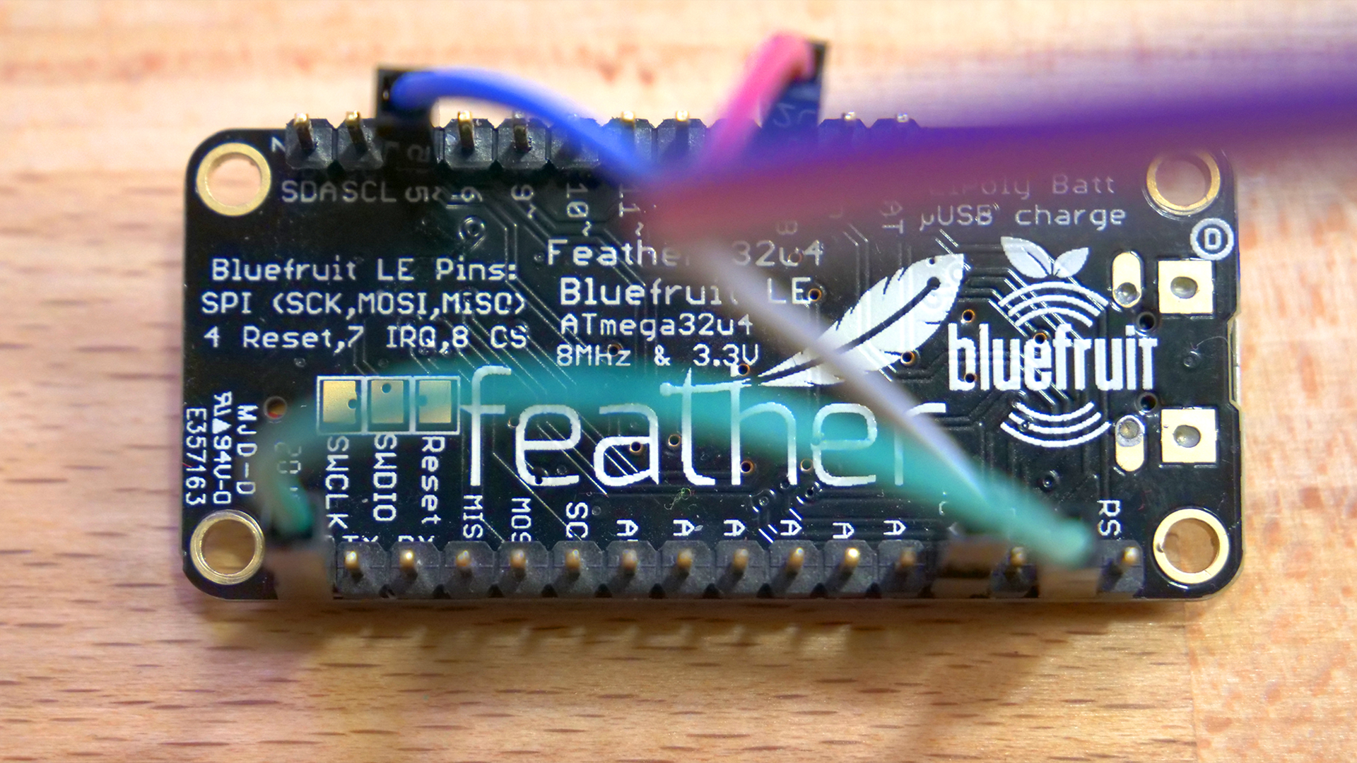
The main part of our solution is a small development board called Adafruit Feather 32u4 BlueFruit LE. Essentially, it’s an Arduino-compatible board with Bluetooth LE module, and we’ll use it to read input on one of the pins. The input will be created by activating a pin on the Einsy RAMBo / Mini RAMBo motherboard – we can do that by including a short piece of custom G-Code. The Adafruit board will emulate a Bluetooth keyboard and a keyboard button press, which is recognized as a remote trigger signal by your smartphone. Selfie sticks work the same way. The advantage of this solution is the simplicity and price. There’s nothing to solder, no resistors required… it’s almost plug-and-play. And even though you need to upload the code into the board, you don’t need to know anything about programming. The usual price for the Adafruit board is around 24 USD, but keep your eye out for various sales, you can often save a few dollars.
Pros of this solution:
- + Wireless
- + No soldering needed
- + Doesn’t need an external power supply
- + Compatible with all modern smartphones (with Bluetooth LE)
- + Easy to configure, no programming skills needed
- + Bluetooth remote trigger, does not need Wi-fi
- + The board can be used for tons of other projects when you’re not printing anything
Here’s what you need for MK3/S:
- 1x Adafruit Feather 32u4 Bluetooth LE
- 3x Jumper cable M-F, about 20 cm (10 inches)
- 1x Jumper cable F-F, about 5 cm (2 inches)
- (optional – for the case) 2x M2.5×12 screw, 2x M2.5 bolt
- (optional – for the case) 2x 2.2×9.5 self-tapping screw
Here’s what you need for MK2S/2.5/2.5S:
- 1x Adafruit Feather 32u4 Bluetooth LE
- 3x Jumper cable F-F, about 20 cm (10 inches)
- 1x Jumper cable F-F, about 5 cm (2 inches)
- (optional – for the case) 2x M2.5×12 screw, 2x M2.5 bolt
- (optional – for the case) 2x 2.2×9.5 self-tapping screw
…and of course a smartphone with Bluetooth LE support.
Preparing the board
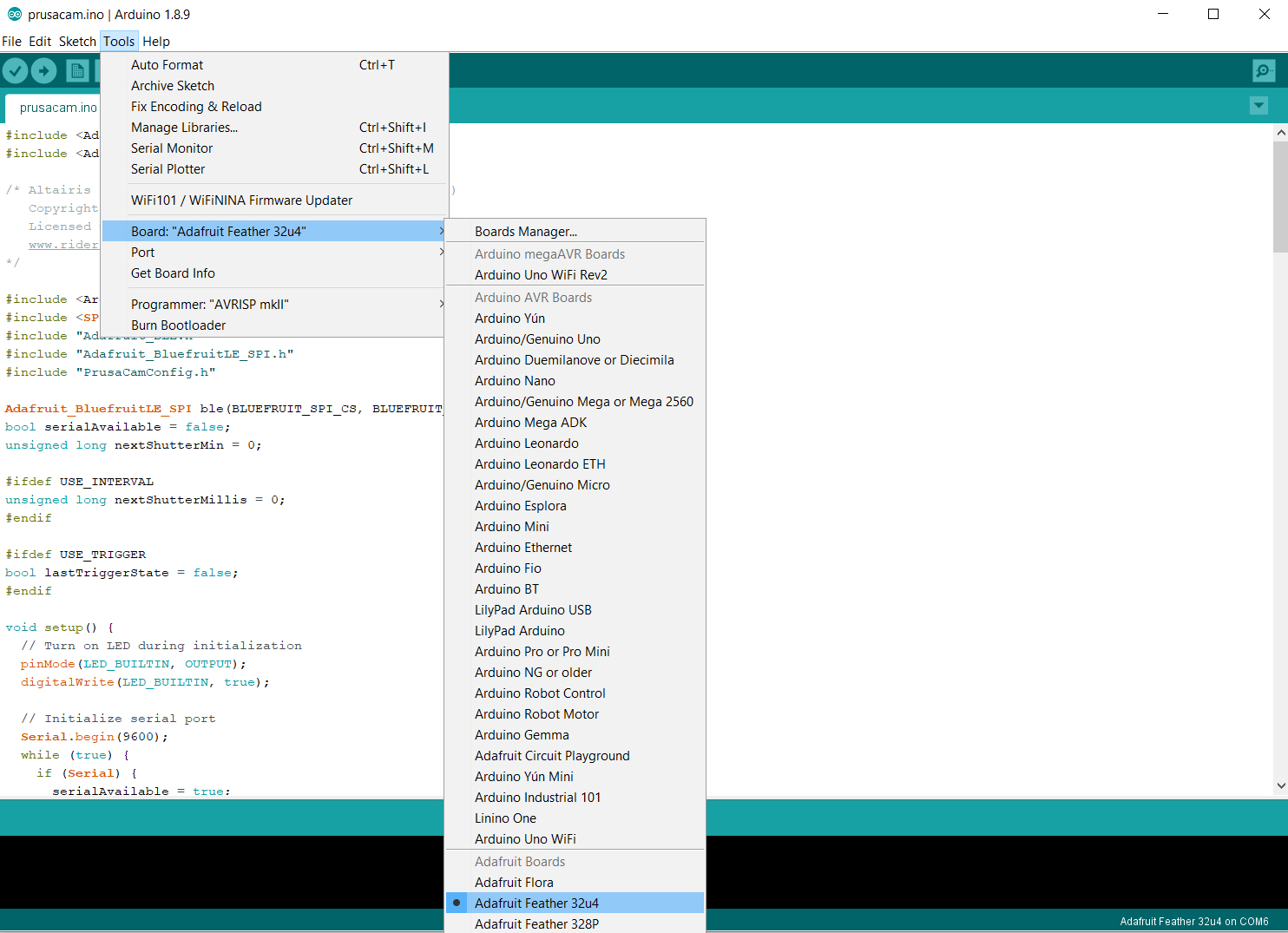
- First of all, start by downloading and installing the latest version of Arduino IDE – we need it to upload our ready-made code to the board.
- Next, start Arduino IDE and add support for Adafruit boards. Open the Preferences menu (File->Preferences on Windows, Arduino -> Preferences on OS X).
- Look for an input field labeled “Additional Boards Manager URLs” and paste the following URL in it: https://adafruit.github.io/arduino-board-index/package_adafruit_index.json – if there are already URLs in this field, just add a comma behind the last one and paste the new one. Click OK
- Go to Tools -> Board menu, click Boards Manager and in the Type drop-down menu select “Contributed”. Select Adafruit AVR boards and click Install. Once it’s done, restart Arduino IDE.
- Go to Tools -> Library -> Library manager and find “Adafruit BLEFirmata” and install it
- Go to Tools -> Board again and find Adafruit Feather 32u4. That’s all regarding the configuration.
Just in case the board is not correctly recognized by Windows, you might need to download the drivers. Now, the only remaining things to do is to connect the board to your PC with a microUSB cable and upload the files.
- Download PrusaCamConfig.h and PrusaCamFeatherBT.ino from Github.
- Open the .ino file in Arduino IDE, select Adafruit Feather 32u4 in Tools -> Board menu and select the correct COM port in Tools -> Port. Press the Upload button to upload your project to the board. Programming is done!
Optional case
If you would like to go for a slightly tidier solution, you can print a little case for the board, which can be attached to the side of the printer. You can grab the .STL files on GitHub. The board doesn’t produce any heat, so you can safely use PLA to print it. Use two M2.5×12 screws and M2.5 bolts to attach the case to the frame.
Connecting the board and smartphone
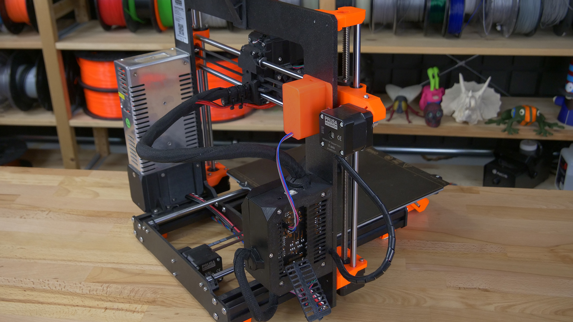
The easiest way how to connect the board to the Original Prusa i3 MK3/S is to use the J19 socket on the Einsy RAMBo motherboard – that’s the socket used to connect Raspberry Pi Zero W. In case you already have a RasPi there, it’s expected you will use OctoLapse to record your time-lapses.
There are two ways how to connect Adafruit board to the Einsy RAMBo – either from the backside, where new printers have a small door or from inside of the electronics case. Connecting it from inside is a bit more complicated due to the number of cables already there, but you can actually manage it easily with a bit of patience.
The Original Prusa i3 MK2S / 2.5 / 2.5S doesn’t have this socket, which means that you need to disconnect the filament sensor and connect the remote trigger instead of it.
Refer to the illustration below to learn how to connect the board correctly. The Back side of the Einsy RAMBo can be accessed through the back door, the Front side is accessed by opening the main front door on the electronics case (secured by a screw).
WARNING: YOU ARE ABOUT TO CONNECT AN ELECTRONIC DEVICE TO YOUR 3D PRINTER. WRONG WIRING CAN LEAD TO POTENTIAL DAMAGE – ALWAYS DO THIS WITH THE PRINTER TURNED OFF! DOUBLE-CHECK YOUR CONNECTIONS BEFORE STARTING THE PRINTER!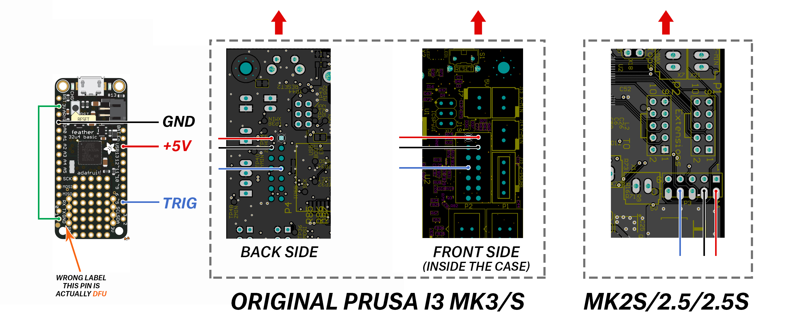
Start the printer and wait for a few seconds until the Adafruit board fully boots up. Then, on your smartphone, open the Bluetooth menu and look for new devices. You should see Altairis PrusaCam Feather BT, which is identified as a keyboard – connect to it.
Preparing the G-code
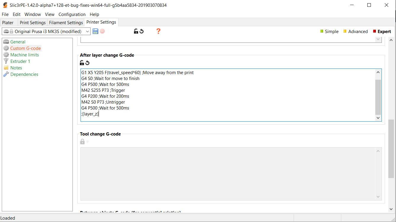
The best way how to create fluid timelapse is to take a picture after each layer. This is done by adding a piece of custom code to every layer change. Slic3r PE can do this for you.
The code we’re talking about is this (for MK3/S):
;AFTER_LAYER_CHANGE
G1 X5 Y205 F{travel_speed*60} ;Move away from the print
G4 S0 ;Wait for move to finish
G4 P500 ;Wait for 500ms
M42 S255 P73 ;Trigger
G4 P200 ;Wait for 200ms
M42 S0 P73 ;Untrigger
G4 P500 ;Wait for 500ms
;[layer_z]
In case you have an MK2.5/S, you need to change the pin number to P20:
;AFTER_LAYER_CHANGE
G1 X5 Y205 F{travel_speed*60} ;Move away from the print
G4 S0 ;Wait for move to finish
G4 P500 ;Wait for 500ms
M42 S255 P20 ;Trigger
G4 P200 ;Wait for 200ms
M42 S0 P20 ;Untrigger
G4 P500 ;Wait for 500ms
;[layer_z]
Let’s take a look at each step:
G1 X5 Y205 F{travel_speed*60} – this code tells the extruder to move all the way to the side and the print bed to move all the way forward
G4 S0 – waits until these moves are finished
G4 P500 – wait 500 milliseconds
M42 S255 P73 – M42 G-code activates pin 73 (P73) with 5V. S0 = 0V, S255 = 5V. Since we’re using fixed (manual) focus, we don’t need to worry about focusing the camera first
G4 P200 – wait 200 milliseconds
M42 S0 P73 – disabling (S0) pin 73, aka “untrigger”
G4 P500 – wait 500 milliseconds
After these actions are performed, the printer returns the extruder and print bed back to the original position and continues the print. This procedure won’t affect the look of the model in any way.
Adding custom G-code is easy. Open Slic3r PE, go to the “Printer Settings” tab and look for “Custom G-Code” section. Add the code above into the “After layer change G-code” textbox and save the profile as something easy to remember – e.g. Original Prusa i3 MK3S Timelapse. It’s advised to save this as a new printer profile, because when you slice an object with these settings, it will always perform the “move to the side” action after each layer, no matter whether a camera is connected or not. This, of course, makes the printing times noticeably longer.
Once you have the custom G-code implemented, you can slice the object as usual – you can choose any layer height or material.
Keep in mind that printing objects with the timelapse mode on will extend the print time noticeably.
Recording time lapses
Everything is ready to go. Find a good place for your phone near the printer and don’t forget to plug in a charger in case you’re going for a longer printer. Disable screensavers, sleep modes or other features that would turn the screen off after a certain amount of time. Open the camera app and start the print job, the rest is automated. At the end of each layer, the extruder will move to the side and the Adafruit board will send a remote trigger event to your smartphone, which will take a photo.
Several things to keep in mind:
- You will get better results if your smartphone supports “Pro” mode – it can have different names, but it basically gives you greater control over the phone’s camera: set the focus to manual override and also consider setting the exposure to a fixed number. Smartphone camera apps are often trying to over-analyze the scene, so you might end up with a bunch of photos that have different colors and exposure, just because your phone thought that the scene is suddenly too dark.
- Use a phone charger to keep your phone running during long prints. It’s recommended not to keep your phone on a charger for days or weeks – see your phone’s manual for more info regarding your phone model
- Consider changing the photo size in the camera app’s settings – usually, you don’t need a 24MPix photos when you want to publish the timelapse as a regular FullHD video. Changing the size of photos also helps to conserve space in your phone’s memory, because there can be hundreds of photos captured during one print.
- If you have an automatic upload to cloud set up, consider turning it off for the print job in case you have limited space and/or data plan
There’s a number of ways how to create a time-lapse video. Both iOS and Android devices have various apps available in their respective app stores, or you can download the photos to your PC and use the guide we published at the end of our previous article.
We could do a similar solution to this even with the Raspberry Pi Zero W, right? It has bluetooth functionality. Would we need another GPIO header just to be the “activate shutter” pin?
Any chance to get a version of this that uses more standard bluetooth modules like an esp32 or a simple arduino with a bluetooth module attached?
the feather used here is out of stock at adafruit and it costs 30 bucks + the huge shipping fee to get this thing to europe.
These cheaper boards cannot emulate Bluetooth keyboard. At least we couldn’t get it working.
I don’t know if this will help your shipping, but you should be able to find this feather at DigiKey. (DigiKey carries a large portion of AdaFruit’s catalog, in fact here are the 3 versions (difference is type or lack of headers) at DigiKey https://www.digikey.com/products/en/rf-if-and-rfid/rf-evaluation-and-development-kits-boards/859?k=Adafruit%20Feather%2032u4%20BlueFruit%20LE .) My thought is maybe DigiKey as a major parts supplier has better contracts with shippers for international shipping than AdaFruit does. As always, YMMV.
We have stock in the UK and Germany, if that helps with the shipping at least 🙂
https://shop.pimoroni.com/products/adafruit-feather-32u4-bluefruit-le
https://shop.pimoroni.de/products/adafruit-feather-32u4-bluefruit-le
Hi! When i try to verify, or upload the .ino file in Arduino IDE i get an errormessage.
I have installed the board and the library, the adafruit is connectet and answered on com-port, but i can not upload the .ino -file.
Arduino IDE will always have an error while verify or upload it.
Are there any steps i have to check also?
Thanks
Michael
Is there a chance to get these 2 files, the .ini and the .h file, which you have used, without using github? 🙂
Please clarify what error message you got.
Micheal, I have followed the steps in the final part, Uploading the code the the device in Arduino, The string within “PrusaCanFeatherBT.ino” fails verification (Multiple libraries were found for “SPI.h”
PrusaCamFeatherBT:9:10: error: Adafruit_BLE.h: No such file or directory) Can you please help me get this to work?
How about using the X,Y or Z max endstop pins on the mini rambo (MK2S)? They’re free and not used? Can they be activated via GCODE? Or we will need to redefine them as outputs in the arduino code?
ESP32 implementation for HID over GATT Keyboard and Mouse (Bluetooth Low Energy). Including serial API for external modules (similar to Adafruit EZKey HID)
https://github.com/asterics/esp32_mouse_keyboard
I am aware of this project, but it’s built for Espressif IoT Development Framework (ESP-IDT). I’m trying to stay with Arduino IDE, as it’s more approachable and common and I wasn’t able to find a way how to use BT HID from Arduino IDE on ESP32.
Hello, i have a
BN: Adafruit Feather M0
VID: 239A
PID: 800B
How to get it working ?
Hope you can help me
Thanks
Roberto
I tried to combine Arduino Uno (or Nano) with HM-10 CC2541 BLE module. The overall costs for the clones from China are roughly 4$. Sure HM-10 does not support HID by default (emulation of keyboard), but some clever people made a firmware that will handle simple commands like sending a keycode.
You can find a tutorial here: https://imgur.com/a/KWmz6
There is also sample Arduino code, sure you need to adapt a bit for this purpose but in fact it just reads one binary input and sends a keycode. So changing a key code to “Enter” (did not found volume up) will make it.
Here there is a guide how to flash proper firmware using just an Arduino board, no programmers: http://forum.arduino.cc/index.php?topic=393655.msg2709528#msg2709528
I spent three hours to make it working, but now I have a chip for hours of playing 🙂
I’m aware of these cheap BT chips, but had not enough time to play with them and their firmware yet. If you have working solution, maybe you can send pull request to https://github.com/ridercz/PrusaCam/ or publish some article with howto. If you need help with publishing etc., contact me, I’ll help you.
i cant get this uploaded to the board just like Leakim1409. the board’s connected properly, but i keep getting error for #include “Adafruit_BLE.h”
and #include “Adafruit_BluefruitLE_SPI.h”. there is no file in the gethub for this and it wont upload.
You most likely don’t have the Adafruit BLEFirmata library installed, see “Preparing the board” step 5.
Is it possible to install the Adafruit Feather 32u4 BlueFruit LE on the front side of the Einsy board while the Raspberry Pi is mounted on the back side???
Or can we use the Raspberry Pi for this Bluetooth-Remote-Shutter function too???
It’s most likely not possible and definitely not a supported scenario. If you are using Raspberry Pi with OctoPrint or similar solution, then you can use it to do timelapse as well.
This solution is for those who do not want to use RasPi, but want to have timelapse.
Hi Dragon 2781,
I would like to answer a question from your post of April 2019. It a bit late, I know, but I was developing the code you needed when I saw your post and I thought you were thinking the same as me. I developed Python code that runs on a Raspberry Pi 1 to 4 that uses Bluetooth to trigger pictures or screenshots that will do what you are looking for. I use it to 3D print timelapse videos at 4k reolution using smartphones. The software can trigger up to 4 smartphones simultaneously. As we see in the UK bettr late than never – here is a YouTube link that may be of use to you –> https://www.youtube.com/@MattJemRise
Hope this is may be of use for you. Thanks Matt P
Burned twice now on Prusa blog tutorials. I don’t want to learn another programming environment, and going by the steps above, I shouldn’t have to. But no, the library is missing, the code won’t verify and I’ll have to spend a few hours learning how to fix something I didn’t care a damn about to start with, just so I don’t feel like I wasted my money buying the parts for this “simple” solution.
Never mind. Sorry for the rant. I figured it out, and it wasn’t hard. Keep up the good work guys!
eXcelonPrime, what did you do to get the code to verify?
I had to download and install the BLE library, which is what it sounds like you need as well. Here’s the link to the Adafruit tutorial and download:
https://learn.adafruit.com/adafruit-feather-m0-bluefruit-le/installing-ble-library
After that everything worked perfectly.
Hope it helps!
Hi All,
Which parts need to order in link below
https://www.adafruit.com/product/2829
Thanks
Hello I do have some problems with the compilation.
See error message below.
…
Arduino: 1.8.9 (Windows Store 1.8.21.0) (Windows 10), Board: “Adafruit Feather 32u4”
PrusaCamFeatherBT:15:26: error: Adafruit_BLE.h: No such file or directory
compilation terminated.
exit status 1
Adafruit_BLE.h: No such file or directory
…
I have done step 5 and installed Adafruit BLEFirmata.
It is also shown under libraries as installed.
What do I do wrong?
Maybe it is because I cannot select a port under TOOLS.
But here also I installed all the drivers.
The board itself is blinking RED.
Fast blinking at the usb connector and a 3 times fast – pause – 3 times fast and so on on the opposide side.
Thanks for helping a absolute beginner with such stuff,
Roland
Problem solved see post below
Okay, after finding the post from eXcelonPrime I installed also the Adafruit_BluefruitLE_nRF51 library.
Now the compilation runs.
But I cannot upload it to the board because I cannot choose a port.
Maybe I’ll drink a coffee first …
Yeah, the coffee helped!
I changed the usb cable and now it works!
What a f… that shitty cable now it landed in the rubbish bin!
Hello there,
I installed the system without any problem, but when the layer is longer in any layer, the phone comes out in the camera application and the waiting time cannot be extended while the camera is on. does anyone have a solution to this?
we need more information Pursa i3
I connected everything to the instructions and it worked great. Then I changed the EINSY enclosure, so I had to reconnect all the cables. Now the phone connects properly, but it looks like the trigger did not work. So I replaced all the cables what did not help. Next I reconnected them from the front to the back of EINSY – still the trigger does not activate. I wonder if I could damage the pin on EINSY so I would like to plug this trigger into another pin. Is it possible to change P73 to some other one in G-code?
Any thoughts on the Adafruit Feather nRF52 Bluefruit LE – nRF52832 board instead? It uses the nRF52 chip instead of the 32u4.
Has anyone found a need to use a pulldown resistor? My board is detecting false positives and I found on an adafruit forum a complaint about the board being too sensitive. Does the MK3S Einsy Rambo have a pulldown built into the pi socket pins?
Hi Michal Altair Valasek,
thank you for this great tutorial! I created a video tutorial showing the steps to my first 3D print timelapse. Hope it helps others to do the same!
https://youtu.be/Yh5I7jCLY5o
Best regards!
MikrocontrollerProjekte
How do you know that selected pin is #73? What about other pins? Can any of these be used as well?
im having an issue where when i have the feather plugged in, its triggering the smartphone all the time, every 5-10 seconds with no gcode loaded and printer not running. is the firmware to the feather at fault? i have re-uploaded the firmware successfully, and it does the same thing.
Micheal, I have followed the steps in the final part, Uploading the code the the device in Arduino, The string within “PrusaCanFeatherBT.ino” fails verification (Multiple libraries were found for “SPI.h”
PrusaCamFeatherBT:9:10: error: Adafruit_BLE.h: No such file or directory) Can you please help me get this to work?
Getting a lot of these same errors. I have all the correct libraries as in the above directions and no luck. Looks like this tutorial is out of date now.
Hi,
I got this prusacam successfully tested just a while ago…
but I realised that the photos only being taken for every 2 layers… instead of every layers…
I wonder is that normal for this?
Thanks….
Great series of lessons, saw something similar in this article https://celltrackingapps.com/snapchat-cheating/ . There’s also a lot of information about cheating on snapchat.
Does not work anymore. If anyone in 2022 gets this let me know what you did.
Followed the steps to a tee and no luck.
To those trying in 2022 and beyond, here’s what I did to make it work ON TOP of the tutorial. Follow the tutorial first, then:
– Go back to Tools -> Manage Libraries
– Add Adafruit BluefruitLE nRF51 (version 1.10.0 worked for me)
– Replace the includes at the top of the file with the following instead:
#include
#include
#include
#include
#include
#include
#include
#include
#include
#include
#include
#include
#include “PrusaCamConfig.h”
The code itself still works great, just the libraries it depends on have been updated. Hopefully this tip gets it working for those of you that have been having trouble.
Prusa comments messed up my formatting. This is the includes you need. Make sure you surround the include in “” except the final one, e.g.
#include Adafruit_ATParser.h
#include Adafruit_BLE.h
#include Adafruit_BLEBattery.h
#include Adafruit_BLEEddystone.h
#include Adafruit_BLEGatt.h
#include Adafruit_BLEMIDI.h
#include Adafruit_BluefruitLE_SPI.h
#include Adafruit_BluefruitLE_UART.h
#include Adafruit_BLE_Firmata.h
#include Adafruit_BLE_Firmata_Boards.h
#include Arduino.h
#include SPI.h
#include “PrusaCamConfig.h”
Well, I give up Prusa. I tried.
Less than sign at the start, greater than sign at the end around each of those includes above (except “PrusaCamConfig.h”)
For anyone who wants this to work – Use this library instead of the above.
Adafruit BluefruitLE nRF51 (version 1.10.0 worked for me)
They must’ve changed it over the years. Got the code to compile and upload with this.
Many thanks for this project! It worked fine for me except for to very small things :
1) I had to modify the line in the PrusaCamFeatherBT.ino:
– ” #include “Adafruit_BLE.h” => should be replaced by “#include “Adafruit_BLE_Firmata.h””
2) I had also to install the “BluefruitLE_SPI” library which is called in the ino file (
#include “Adafruit_BluefruitLE_SPI.h”). This library is not installed by default.
Thanks again!
Making 3D print time lapses with your smartphone camera can be a great way to showcase your printing skills and share them with others. The article provides a simple and affordable solution using a Bluetooth remote trigger and Adafruit Feather 32u4 BlueFruit LE board. This solution is wireless, requires no soldering, and is compatible with all modern smartphones with Bluetooth LE functionality.
The article provides a detailed guide on how to prepare the board and upload the code. It also lists the required components for MK3/S and MK2S/2.5/2.5S printers.
Overall, this is a great solution for those who want to make 3D print time lapses without spending too much money or time on setting up complicated systems. The Adafruit board can also be used for other projects when not in use for printing.
One thing to keep in mind is that Bluetooth connectivity can sometimes be unreliable, so it’s essential to test the remote trigger before starting a time-lapse recording to ensure that it’s working correctly.
The provided link to https://electronicshacks.com/ provides additional details and instructions that can be helpful for anyone interested in this solution.
Is there a way to use this project with the Prusa XL?
Is it possible to use this with MK4 ? Where are the pins needed on that printer?