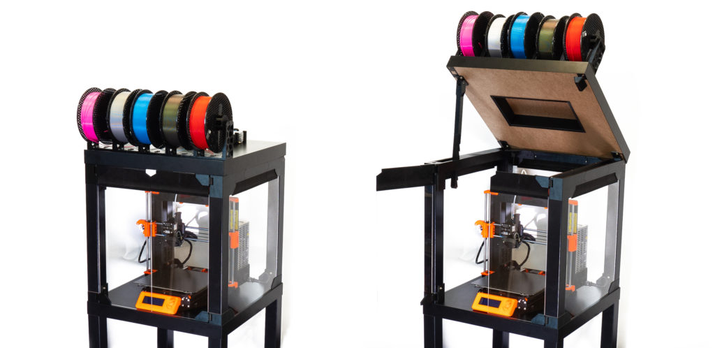
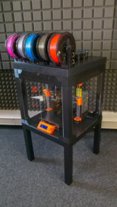
Our first 3D printer enclosure became incredibly popular – and naturally, once we released our new Multi Material Upgrade 2.0 and 2S, people started asking us for an updated enclosure that would accomodate the Original Prusa i3 MK3S (and 2.5S) 3D printer along with the MMU2S unit. So, here it is – and it’s better than ever!
If you have no experience with 3D printer enclosures, let us give you a quick tour of their benefits:
- Stable printing conditions – sudden bursts of cold air and draft in general can negatively impact the printing process. The enclosure will ensure a higher, stable temperature around the 3D printer. Significant differences between the temperatures in the room and on the heatbed can have undesired effects – objects detaching from the print bed, layer warping and poor layer adhesion especially when printing with ABS and ASA
- Less noticeable odors – certain materials can produce somewhat unpleasant smells. The enclosure will contain these vapors during the print. Once the job is finished, you can open the enclosure e.g. next to an open window to quickly vent the unwanted odors
- Noise reduction – if you, for some reason, still think the MK3S is noisy, you can isolate the printer in the box to further reduce the noise. This can be useful e.g. if you want to place the machine directly next to your desk.
- Dust reduction – the enclosure will help to decrease the amount of dust on the bearings and rods of the machine
- Compact setup – The MK2.5S/3S 3D printer, MMU2 unit, filament buffer, five spools and spoolholders, PTFE tubes… there’s a lot of things around the printer. Everything will be neatly organized.
- It’s a cool DIY project 🙂
However, before we begin, we would like to mention that the enclosure doesn’t actually benefit print quality when printing with PLA – actually, if you decide to print with PLA (e.g. Prusament), we highly recommend keeping the front door partially open to give the nozzle (or more specifically – the heatbreak) enough airflow for sufficient cooling. High temperatures combined with PLA materials can lead to partially clogged nozzle. You will see the real benefit of the enclosure when printing with ABS and ASA. Increasing the temperature around the printer and creating a stable environment inside the box will improve the bed adhesion and prevent layer warping. Either way, you will certainly appreciate the compact configuration of all the components.
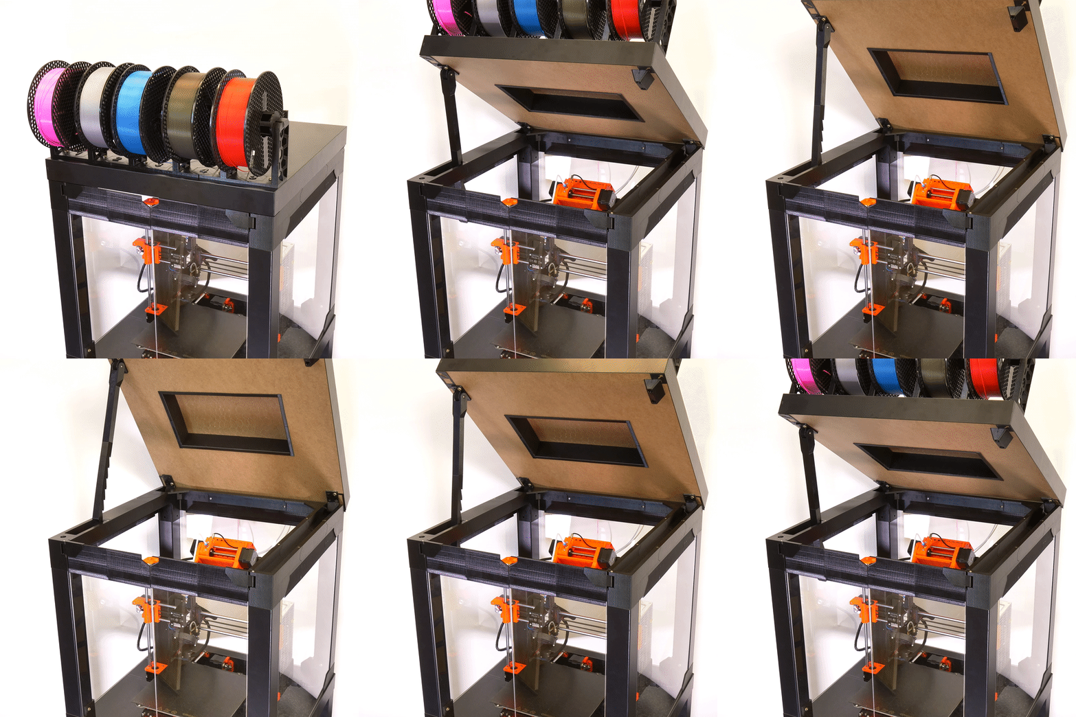
Our IKEA Lack enclosure became incredibly popular (nearly 150,000 downloads of printed parts!), mainly because it’s an elegant and cost-effective solution. Plus, the size of the Lack table is pretty much ideal for our 3D printers. While we’re really proud that we made something so popular, it also made the starting point for the new version more difficult. What if you already made an enclosure? What if you already paid for the acrylic panels? We don’t want you to start from scratch. Instead, we decided to modify the original concept and improve it. We’re keeping the acrylic panel dimensions, and if you didn’t damage the Lack tables too much, you should be able to re-use them. All printed parts are different, though. On the other hand, the enclosure comes with a number of useful new features, such as a semi-automatic locking mechanism of the lid, magnetic hinges and a small compartment for various tools.
The primary goal was to design the enclosure in such a way that anyone will be able to build it at home, using printed parts, regular fasteners and easily accessible materials in general. Non-standard elements are kept to a bare minimum.
So, those were the challenges we had to overcome. Now for the benefits of our solution:
- We kept the original dimensions for acrylic panels (440×440 mm). If you have already built the previous version of the enclosure, you can re-use your current acrylic panels
- We have integrated the filament buffer (part of the MMU2S upgrade) to prevent filament strands from tangling during retractions
- The enclosure can be placed in the corner or between two pieces of furniture – only access to the front and the top is required
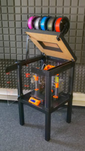
- The MMU2S unit is easily accessible by opening the top cover
- There are 5 spoolholders on the top of the enclosure, which can accomodate 5 filament spools – each up to 89 mm wide
- Re-used parts from the MMU2S package, such as spoolholder shafts
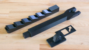
- The top cover can be opened easily – there’s a semi-automatic locking mechanism that holds the cover open. To close it, just lift the cover slightly and pull the locking arm towards you, then close the cover
- Enough room for the orange PTFE tube leading from the MMU2S unit to the extruder
- Robust hinges with integrated magnets that hold the front door closed
- The supporting locking mechanism arm is hidden in the frame when the cover is closed
- A small storage compartment in the frame – useful for storing small tools
What will you need?
Printed parts:
- 1× Printed parts set or in case of 1/8 inches (3.175 mm) thickness acrylic sheets replace some of them by this prints
- 1× 60-degree mounting cover for heatbed cables
Basic parts
- 2× IKEA Lack table
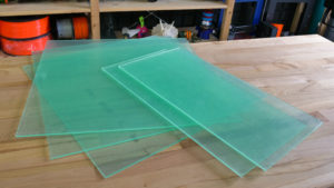
- 3× Clear acrylic sheet 440×440 mm, 3 mm thickness – reused from enclosure V1. If you don’t have these sheets yet, you can order a larger size that doesn’t need 3D-printed extensions, the dimensions are 440×473 mm, 3 mm thickness.
- 2× Clear acrylic sheet 220×440 mm, 3 mm thickness – reused from enclosure V1. If you’re ordering new sheets, you can go for a larger size that doesn’t need 3D-printed extensions. The dimensions are 220×505 mm, 3 mm thickness
Side note: throughout this guide, we will keep using the term “clear acrylic sheet”, but Plexiglass/Plexi glass/Plexiglas can be used without a problem, depending on your preferences.
Fasteners
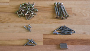
- 35× pan head screw, 5×20 mm
- 4× screw 6×50 mm
- 4× screw 6×30 mm
- 12× screw M3×30
- 4× screw M3×10
- 4× screw M3×18
- 8× neodymium magnet, 20×6×2 mm
In addition, if you want to place PSU outside the enclosure:
- Silver PSU: 3× pan head screw 5×20, 1× screw 3×10 mm, 2× M4 nut
- Black PSU: 3× pan head screw 5×20, 1× screw 3×10 mm, 2× screw M3×12, 2x M3 nut
Tools
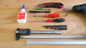
- Philips screwdriver
- Allen key – 2,5mm
- Superglue / Locktite
- Drill + wood drill bits ø 2 mm, 5 mm, 8 mm and 10 mm
- Tape measure
- Snap-off knife
- Ruler
- Pencil or marker
In addition, if you want to place the PSU outside the enclosure:
- wood drill bit ø 12 mm
Printing the plastic parts
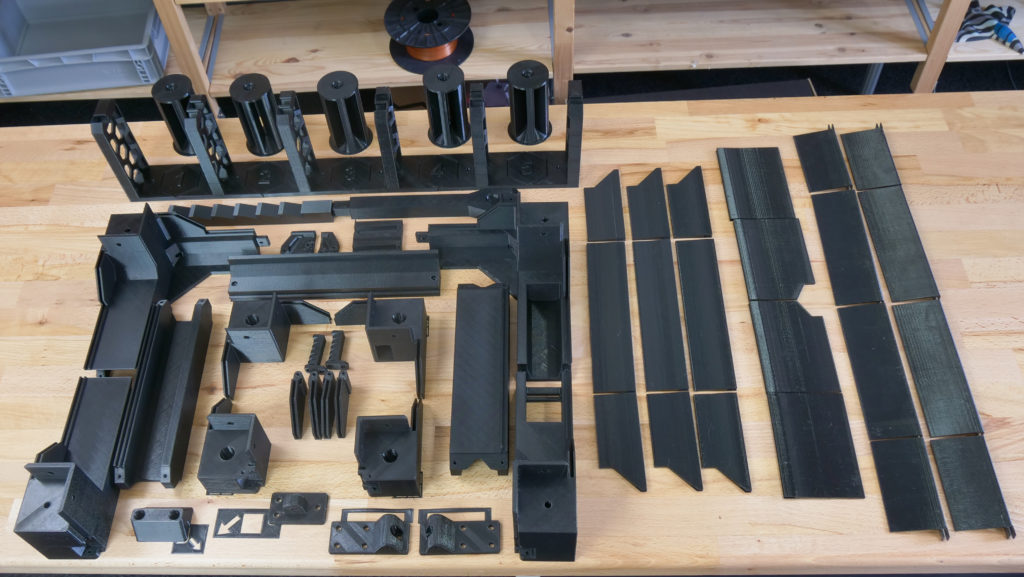
We recommend printing the plastic parts with PETG filament – e.g. Prusament PETG Jet Black. You can use our pre-made G-codes, which are already tested and, of course, sliced with the optimal settings. Or download the .3MF files from the same link and slice them yourselves. Several parts come with a mounting bracket, that will help you position these components and secure them in place. Please, do not remove the mounting brackets before you secure the parts in place. However, do not forget to remove the support material, so the parts can be put together.
Building the box – lower table
The box usually consists of two IKEA Lack tables. Even though it’s possible to place the whole setup onto another Lack table, it will make access to the MMU2S unit and the buffer more difficult.
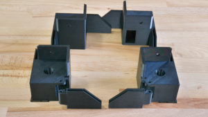
List of plastic parts required for this step:
Placing the Power supply – UPDATE
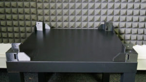
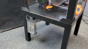
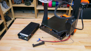
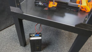
You need to decide whether to remove the power supply from the printer (outside the enclosure) or leave it on the printer (inside the enclosure), depending on the intended use of the machine. If you do not plan to run long prints from materials that require higher temperatures (ASA, ABS, PETG), you can leave the PSU on the printer and leave the front door ajar when printing. However, if you print at higher temperatures, the heated bed warms the air inside the enclosure to about 40°C (when the ambient temperature is 27 °C). In this case, it is advisable to place the PSU outside the enclosure. Long-term use of the PSU at high temperatures (above 45°C) may shorten its life. On the other hand, leaving the PSU on the printer will make it easier to remove the printer from the enclosure. Have you decided to keep the PSU inside the enclosure? Skip the next assembly step. Otherwise, follow the instructions below.
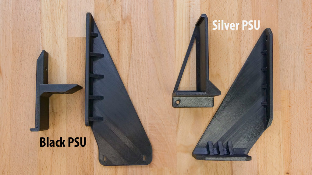
The assembly procedure and printed parts vary depending on the PSU type on your printer.
List of plastic parts for this step:
Silver PSU
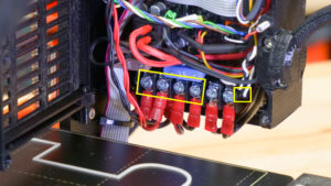
- Open the Einsy electronics cover and disconnect the power cables and power-panic cable from the Einsy board terminal (2x black cables with the fork, 2 red cables with the fork, 1 black and white twisted pair).
- Carefully cut off the zip ties that hold the cables, unscrew the PSU, and remove it along with the cables from the frame.
- Mount the frame brace in place of the PSU.
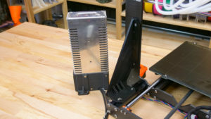
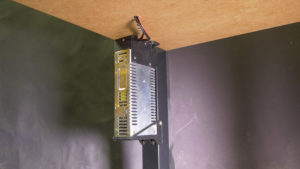
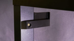
- Mount the printed PSU holder on the left rear leg of the lower table. See the photo below.
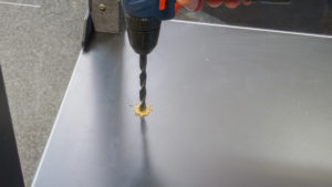
- Drill a 12 mm diameter hole in the lower table. The hole should be placed directly under the Einsy electronics (120 mm from the left edge and 220 mm from the back edge). Insert the cable tube into the hole.
- Slide the PSU into the holder and secure the PSU with a screw to prevent it from moving.
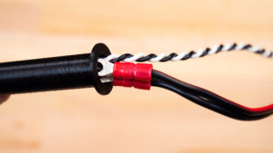
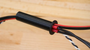
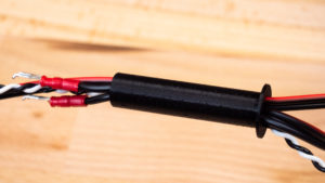
- Pass the cables through the cable tube. The cables must be pulled gradually and the correct order must be followed. First, pull the twisted black-and-white cable. Then continue with the first pair of black and red cables. Finally, pull the second pair of black and red cables. It can be slightly difficult to pull the cables through – try adjusting them and find the optimal position of the terminals to create a passage. If you cannot pull the cables through, separate the beginning of the black cable from the red one and push them separately.
- Connect the cables back to the Einsy electronics. Remember the correct polarity of the cables. If you’re not sure, check out the assembly manual.
Black PSU
- Remove the plastic cover on the power supply labeled “PRUSA”. Disconnect all cables connected to the power supply.
- Unscrew the power supply and remove it from the frame.
- Remove the zip ties that hold the cables on the frame and remove the PSU cables from the bundle. However, do not disconnect the cables from the Einsy board!
- Secure the remaining cables with a zip tie.
- Mount the frame brace in place of the PSU.
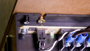
- Mount the printed PSU holder on the left rear leg of the lower table.
Check out the photo below. - Drill a 12 mm diameter hole in the lower table. The hole should be placed directly under the Einsy electronics (120 mm from the left sedge and 220 mm from the back edge). Insert the cable tube into the hole.
- Pass the cables through the cable tube. The cables must be pulled gradually and the correct order must be followed. First, pull the twisted black-and-white cable. Then continue with the first pair of black and red cables. Finally, pull the second pair of black and red cables. It can be slightly difficult to pull the cables through – try adjusting them and find the optimal position of the terminals to create a passage. If you cannot push the cables through, separate the beginning of the black cable from the red one and pass it separately.
- Connect all cables to the power supply. Remember the correct polarity of the cables. If you’re not sure, check out the assembly manual.
- Place the power supply into the bracket and secure it on the terminal board side with one screw to the table.
- Remount the power supply cover labeled “PRUSA”.
Building the box – upper cover
List of plastic parts for the upper plate:
Hollowing the upper cover
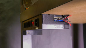
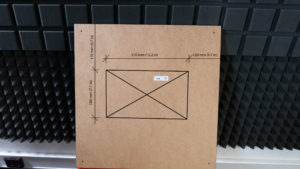
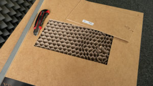
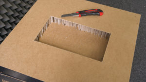
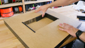
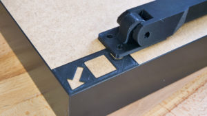
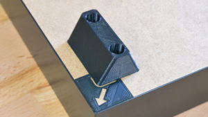
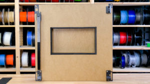
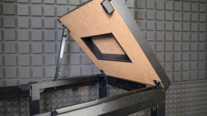
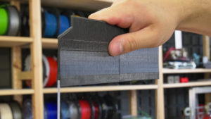
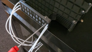
To accomodate the orange PTFE tube leading from the MMU2 unit to the extruder, we need to cut away some material from the table top. Turn it upside down, so you have access to the underside (light brown color). Use a ruler and a pen to draw a rectangular shape with the dimensions and placement based on the photo above. Take a snap-off knife and a ruler and start by cutting a rectangular opening. Then, use the knife to remove the paper honeycomb pattern inside the table top – leave the top plate untouched, there’s no need to make a hole through the whole panel (see the third photo above). Take the printed parts and put them around the opening to prevent the paper infill from falling onto the printer.
Supporting arm for the top cover
List of plastic parts for this step:
Hinges, supporting arms and centering cap
List of plastic parts for this step:
1× Prusa_MMU_enclosure_centering_part
1× Prusa_MMU_enclosure_top_desk_hinge_right
1× Prusa_MMU_enclosure_top_desk_hinge_left
all included in Prusa_MMU_enclosure_4.3mf
Throughout this step, make sure that the table top is facing the right way. The cutout is not directly in the middle! The top edge of the cutout is the one that’s 170 mm from the edge of the table.
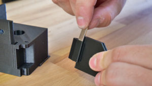
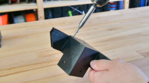
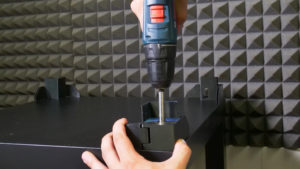
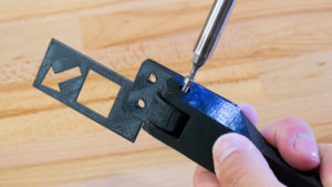
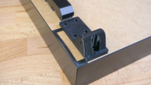
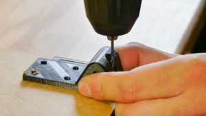
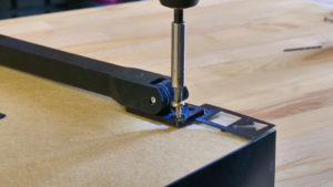
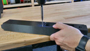
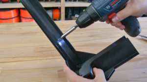
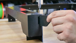
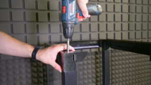
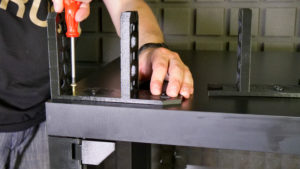
Every part that needs to be secured to the table top comes with a mounting bracket that will help you align it and secure it in place. Before you secure the parts with screws, we recommend to drill the holes first – use a 2mm drill bit. Then, secure the parts with 5×20mm screws.
The front left corner is where the supporting arm goes. Front right corner is the place for the centering cap. Hinges go to the back.
Preparation of the rear acrylic sheet window
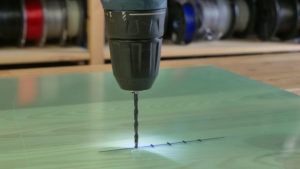
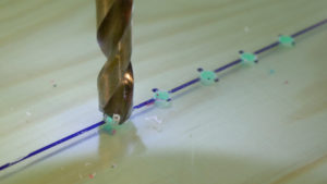
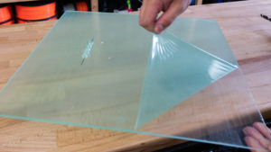
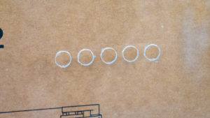
Next, we need five circular openings in the rear acrylic sheet window – these are for the PTFE tubes. If you don’t have the holes there yet, you need to drill them – this can be done with standard equipment, but do not apply excessive force. The holes should be placed 320 mm from the bottom edge of the sheet and centered horizontally. The distance between centers of the holes is 15 mm. To ensure that the PTFE tubes can move freely through the holes, you should use a 10mm drill – smaller holes could result in trouble with filament movement inside the PTFE tubes.
To drill these holes, start with a ruler and a marker. Mark down the center points for all holes and use a 2mm drill bit first. Then move onto a slightly larger drill bit (e.g. 4-5 mm). Then increase the drill bit size again, until you reach the 10mm drill bit. It’s necessary to move by small increments to prevent the acrylic sheet from breaking. Also, make sure the acrylic panel lays flat on a wooden surface during this process – again, to stop it from breaking.
Assembling the U-frame
List of printed parts for this step:
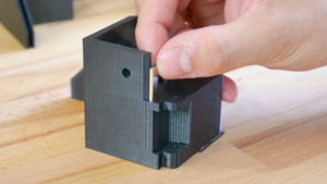
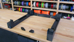
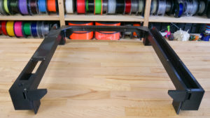
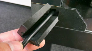
To ensure that the top of the enclosure is strong and firm, the U-frame must be robust. The left side of the U-frame contains a slot for the supporting arm, the right side contains a storage compartment for various small tools.
Place neodymium magnets in the front corners and attach the hinge to the corner part with an M3×30 screw. Assemble the frame on the ground, then flip it upside down. Sides are secured by 4 pieces screws M3 x 30 and the back side is screwed by two pieces of M3 x 10. Exercise caution when moving the frame around, so you don’t damage the printed parts.
Attaching the acrylic sheet windows and the U-frame
List of printed parts for this step:
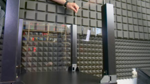
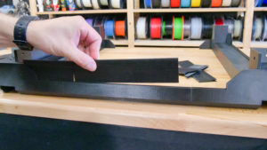
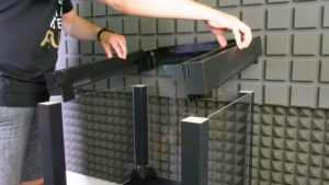
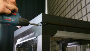
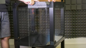
If you have the acrylic glass sheets in 440×440mm dimensions, start by attaching the extensions to the U-frame. If you have new clear acrylic sheets (440×473 mm), you won’t need the extensions. Insert the rear and side acrylic sheets between the legs of the upper table. Make sure the rear window has the five holes for PTFE tubes in its upper part. Finally, attach the U-frame onto the top of the enclosure. Each corner part must be secured with a 6×50mm screw (from the top). Optionally, it’s possible to secure the frame from the inside using two 5×20mm screws.
Attaching the top cover
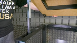
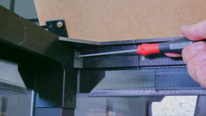
Insert the supporting arm into the hole in the left top corner and place the cover (desk top) onto the enclosure.There are two openings for two M3×18mm screws on the sides. After you tighten these screws, you can open the cover and add two more screws from the inside.
Attaching the door panels
List of printed parts required for this step:
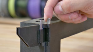
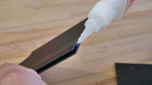
First, attach the extensions onto the door panels, then insert the acrylic sheets into the hinges. Optionally, use superglue to secure the parts.
Mounting the filament buffer and spoolholders
List of printed parts required for this step:
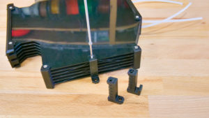
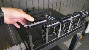
You will need to remove two spacers from the buffer (on the sides – see the photo above), these are called s-buffer-spacers. Replace them with the new printed versions (Prusa_MMU_enclosure_s-buffer-spacer). The modified buffer spacers have holes that are used to secure the buffer to the enclosure. Once you replace the spacers, place the buffer in the center of the top cover and align the rear edge of the buffer with the rear edge of the cover. Do not pull the PTFE tubes through the holes in the rear window yet.
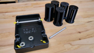
Next – the spoolholders. They consist of three parts. Place them 20 mm from the front edge of the top cover. Then use six 5×20 mm screws to secure them in place. Take the aluminum tubes/rods from the original spoolholders and insert them into the center of 3D printed cylindrical holders.
Alternate heatbed cable mount
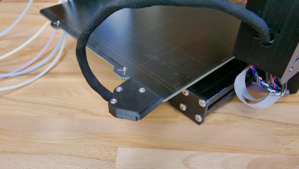
Since the cables leading to the headbed can collide with the rear panel of the enclosure, we recommend switching the heatbed cable connector cover – the updated one will allow you to attach the cables under a 60-degree angle, saving some space in the back.
Placing the printer, attaching PTFE tubes
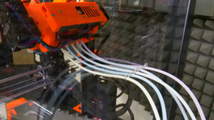
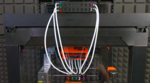
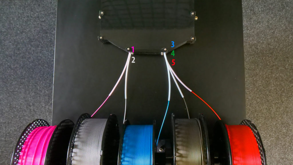
The printer should be placed in a position, where the front edge of the display case will double as a door stop. Open the top cover and pull the PTFE tubes through the holes in the rear panel in the order depicted in the photo below. Before you attach them to the MMU2S unit, take a sharp knife and shorten them by 115 mm. Be extremely careful not to damage/deform them. This could lead to serious issues with filament movement inside the tubes. The new length of the PTFE tubes should be 535 mm. Once this is done, attach the tubes into the MMU2S unit in the correct order – see photos below for reference. Don’t forget to add screws to stop them from detaching.
Power cable and cable bushing
List of printed parts required for this step:
1× Prusa_MMU_enclosure_cable_bushing
included in Prusa_MMU_enclosure_4.3mf
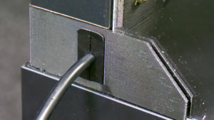
To ease the strain on the cable, we have designed a strain relief bushing. First, insert the power cable into the enclosure through the opening under right back leg and plug it into the printer. Then, bend the bushing in half, place it onto the cable and insert it into the hole.
Inserting filaments
Insert filaments into the buffer in the order depicted in the photo below. 1 is top left, 2 is bottom left, 3 is top right, 4 is middle right and finally 5 is bottom right.
…and done!
Now it’s time to find the best spot for the enclosure. One thing to keep in mind: place the enclosure at least 15 cm from the wall, otherwise the PTFE tubes won’t have enough room and they could deform. Insert the plug into the electrical socket and you can start printing! Great job!
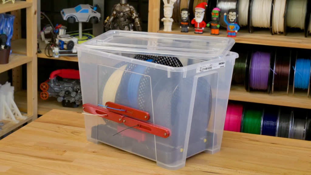
And one more thing – you probably know that the MMU2S is great for printing soluble supports. These water-soluble materials (such as BVOH) are highly hygroscopic, though. They need to be kept in low-humidity environment, ideally even during printing. This is why we have designed a very simple, yet effective drybox. We’ll bring you a complete guide soon. Stay tuned!



コメントを投稿するにはログインしてください。