


Our printers have always been open to various user modifications, and with our GPIO Hackerboard, we extend these possibilities even further. This optional add-on has already garnered significant attention from users who like to experiment and discover new ways to enhance their Original Prusa MK4/S and Prusa CORE One setups. For those who haven’t yet explored the potential of the Prusa GPIO Hackerboard, we’ve prepared a project that utilizes it to create a timelapse video of your 3D print. This example highlights what’s possible, and we hope it’ll inspire ideas for your own modifications.
As a quick side note, this project is designed to let you use high-end digital cameras, allowing you to achieve the best possible picture quality for your timelapses. However, for those looking for a simpler, more integrated solution, we recently released a firmware update for our Buddy3D cameras. This update adds the ability to capture photos for a timelapse directly with the Buddy3D camera itself, which may be a perfect solution for many projects. Check our article about this important update here.
WARNING: All modifications and connections are performed at your own risk. We do not assume any responsibility for damage to any device that may occur, for example, due to incorrect wiring, improper handling, or failure to follow instructions.

Print Timelapse with a Digital Camera
In one of our previous articles, we published a detailed guide on how we create our beautiful timelapse videos using a digital camera and a custom-made cable connected directly to the motherboard in the MK3/S and M2.5/S printers. You can find the original article here.
In this solution, the pins on the motherboard were controlled by G-code instructions, which activated a voltage output on them. The voltage signal then activated a circuit within the cable and triggered the camera’s shutter. This method did the trick, but it was quite complex, as it required connecting DuPont cables directly to the printer’s mainboard pins, creating a risk of incorrect wiring. The GPIO Hackerboard provides a similar, but more elegant solution. It’s connected to the mainboard of an MK4/S or CORE One printer via a simple I2C connector, and the G-code instructions activate one of the Hackerboard’s eight I/O pins, allowing you to easily control external devices.
To create 3D print timelapses, you can use both wired and wireless remote shutters, depending on what your camera supports. The preferred solution, however, is to use a wireless one, as it’s completely isolated from the printer’s electronics and power, keeping your camera safe at all times. We’ll show you both solutions, so you can choose the one that best suits your needs.
Remember: Always turn off your printer before connecting the GPIO Hackerboard, to avoid potential damage to the GPIO Hackerboard or the printer!
Wired Remote Shutter
First, let’s look at connecting a camera to the GPIO Hackerboard with a cable. It’s important to know that different cameras require various methods for connecting and triggering a remote shutter. For instance, some may require an electrical circuit with determined resistors (like the one we built for our Panasonic Lumix DC-GH5 in a previous article), or use specific connectors. Others, however, simply require bridging contacts on a standard 2.5mm jack cable to trigger a snapshot.
For this guide, we will focus on this simple solution, using a cable with a 4-pole 2.5mm jack on both ends. This approach eliminates any need for soldering, simplifying the entire process and allowing you to easily connect and disconnect the circuit as needed.
First, connect the GPIO Hackerboard to your printer (don’t forget to turn it off beforehand). Then, plug one end of the jack cable into the Hackerboard and the other end into your camera. You can turn the printer back on now.

Next, let’s check which segments of the 2.5mm jack connector we need to bridge to make the camera take a picture. Below you’ll find a diagram illustrating which connections trigger autofocus and which trigger the snapshot (this is specific to our camera model). In this case, to trigger the snapshot, we’ll bridge the first (0) and the last (GND) segment of the 2.5mm jack connector. This will be controlled by a few simple G-code instructions inserted into PrusaSlicer.

Before we proceed to PrusaSlicer, let’s quickly set up the camera to get a good view of the print bed and ensure the correct camera settings, including focus. After you’ve completed the settings, switch the camera to manual focus mode.
Open PrusaSlicer, select your printer, and import the model you’ll print. Then, navigate to the Printers tab in the top menu and select the “Custom G-code” item from the menu on the left. If you don’t see this option, switch PrusaSlicer to Expert mode using the dropdown menu located in the upper-right corner of the screen, next to the user icon.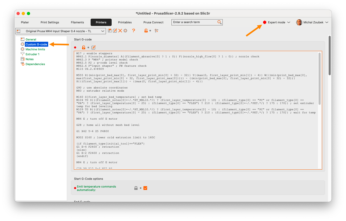
Here you can find G-code commands that are executed during every print, regardless of the printed model, settings, etc. These include instructions that execute before a print starts, after it finishes, or before/after each layer change, and so on. We’ll focus on the Start G-code and After layer change G-code sections. In the Start G-code section, we’ll set Pin 0 as an output by placing this instruction at the very end of the section (text after a semicolon is a comment and does not influence the code):
; Set Pin 0 as output
M262 P0 B0

Next, in the After layer change G-code section, we’ll trigger the actual snapshot sequence. This means that each time a printed layer is finished, we’ll move the print head out of the way to ensure a clear shot and take a picture. The print head waits for a moment and then returns to its original position. The print will continue until the next layer change. Again, we’ll place these instructions at the very end of the section:
G1 X160 Y160 F{travel_speed*60} ;Move away from the print
G4 S0 ;Wait for move to finish
G4 P150 ;Wait for 150ms to give the bed time to stop properly
M265 P0 ;Flip the pin status to 1 to trigger the shutter
M265 P0 ;Flip the pin status back to 0
G4 P250 ;Wait for 250ms to give the camera time to finish the capture

You can save this configuration using the save icon in the top menu, so you can easily switch between normal and timelapse print profiles.
Now, you can return to the Plater tab, hit the Slice button, and send the finished G-code to your printer. After the printing process starts, the camera will trigger consistently after each layer is finished, providing a clear, stabilized shot of your print in progress. With just a few lines of G-code, you’re ready to capture beautiful, layer-by-layer timelapses!
If everything worked out correctly, you should now have many great photos of the ongoing print. Now, we need to turn them into a timelapse video. For this, we’ll use the excellent video editing software, DaVinci Resolve, which is available for free download here.
Creating a Timelapse Video with DaVinci Resolve
First, install and open DaVinci Resolve and create a new project. Before you do anything else, navigate to the Media tab, which is the first icon in the menu at the bottom of the screen. There, in the upper menu, click the three-dot button and make sure the option ‘Frame Display Mode’ is switched to ‘Sequence’. This setting tells Resolve to unite all your imported photos into a single video clip, rather than hundreds (or even thousands, for longer timelapses) of individual images.

Now, switch to the Edit page. To import your photos, locate them in their folder on your computer and select all of them. With all the files selected, drag and drop them into the Master area on the left side of the screen. This will automatically create one or more sequence clips from all the images. Now, drag and drop the clip(s) into your timeline. You can preview the generated timelapse by hitting the play button or by dragging the red line across the timeline. You can also change the framerate and apply various post-process effects to your timelapse video, such as color grading, image stabilization, and more.
Your result can look like this:
You can adjust values in the G-code instructions, such as the position of the printhead or the waiting times to suit your needs. However, keep in mind that the longer travel time increases the risk of filament oozing from the hot nozzle. This can potentially cause print artifacts or stringing. To minimize this problem, use well-dried filament and avoid setting excessively long travel distances for the printhead.
An Important Tip: Images Not Combining?
If you still see imported photos as individual, even after you’ve correctly set the Frame Display Mode to Sequence, the problem is probably with the file naming. DaVinci Resolve needs a continuous numerical sequence to correctly group the files.
- Correct Naming: P2200553.JPG, P2200554.JPG, P2200555.JPG, etc.
- Incorrect Naming: IMG_45.jpg, Photo_46.jpg, IMG_48.jpg (inconsistent prefix or gaps in numbers).
Before importing, ensure all your files have the same prefix and a gapless number sequence.
Now that you know how to create a timelapse video from a wired camera setup, let’s look at a couple of other options for capturing the photos. We’ll start with a wireless remote shutter for your digital camera and then move on to a slightly more advanced method that uses your smartphone.
Wireless Remote Shutter
The wireless solution requires a bit of soldering, but it’s very easy, and the G-code setup is identical to the previous example.
We use Sony Alpha cameras, so we’ve bought an inexpensive Sony wireless IR remote shutter. You can typically order brand-specific or universal versions of such remote shutters, suitable for multiple brands, online for just a few bucks.
Disassemble it to access its internal PCB and identify the pair of contacts that are bridged when the trigger button is pressed. While some buttons have multiple positions for focus and trigger, this particular remote shutter only triggers the snapshot. You can find the correct wiring by observing the PCB or consulting its datasheet.
For the connection between the wireless remote shutter and the GPIO Hackerboard, we will use a 4-pole 2.5mm jack cable once again, but in a different configuration. Instead of having a jack on both ends, we need one end to have exposed wires that will be soldered to the remote shutter’s PCB. You have two ways to get this cable: either buy one pre-made, or make it yourself by cutting a standard jack-to-jack cable and carefully stripping one end to expose the internal wires. Use a multimeter to identify which of the four wires correspond to the correct segments of the jack. We’ll use the same two contacts as shown in the diagram in the previous section – the first (0) and the last (GND) segments of the jack connector. Once you’ve identified the correct two wires, solder them to the button’s contacts on the remote shutter’s PCB. Cut off the remaining two wires and reassemble the remote shutter’s body.
Now, connect the GPIO Hackerboard to the printer and turn it on. Then, plug the 2.5mm jack to the socket on the GPIO Hackerboard, aim the wireless remote at your camera, and start the print with the prepared timelapse G-code sequence. Just like in the previous example, the printer should stop on each layer change and send a (wireless) signal to the camera to take a snapshot.

For those looking for a visual guide on soldering and using the wireless remote shutter and the GPIO Hackerboard, Martin Zeman, a member of the 3D printing community, has put together a great video showcasing the entire process:
Taking Photos with a Smartphone via Bluetooth and ESP32
Do you want to take this project a step further? You can use your smartphone instead of a digital camera. The picture quality is more than good enough to create a great-looking timelapse video. With the GPIO Hackerboard and a small ESP32 board with Bluetooth connectivity, you can build your own wireless remote shutter for your phone.
To build this, in addition to soldering, you’ll also need to do a bit of programming. The setup is more complex, as it involves creating and uploading specific code to the ESP32 board. The board handles the same signal from the GPIO Hackerboard, as in the previous example. However, instead of triggering the contacts of the digital camera, it sends a command to your phone via Bluetooth, simulating a volume button press, which usually serves as the camera’s shutter button.

First, on the GPIO Hackerboard, bridge the JP7 contacts by soldering them to enable the integrated pull-up resistor. Then solder the connections between the boards: connect the Hackerboard’s GND contact to a GND pin on the ESP32 board, and the OUT 7 contact to pin D3 (GPIO5) on the ESP32.
Let’s proceed to the software side. Below, we’ve included the code sample we used to get our specific ESP32 board up and running. Consider it an inspirational starting point for your own project.
Please note: this code is provided as-is and without any warranty. You will likely need to adapt it to work with your particular hardware.
#include <BLEDevice.h>
#include <BLEServer.h>
#include <BLEUtils.h>
#include <BLEAdvertising.h>
#include <BLEHIDDevice.h>
#include <BLESecurity.h>
// Include necessary ESP-IDF headers
#include "esp_gatt_defs.h"
#include "esp_bt_defs.h"
#include "esp_bt_main.h"

// --- Constants ---
const char* DEVICE_NAME = "Prusa-Timelapse-Trigger";
const uint16_t APPEARANCE_CONSUMER_CONTROL = 384;

// Consumer Control Report Bits
const uint16_t VOLUME_UP_BIT = (1 << 0); // 0x0001

// --- GPIO Trigger Pin Configuration ---
const int TRIGGER_PIN = 5; // Use GPIO5 (Pin D5 on XIAO ESP32-C3)
int lastPinState = HIGH; // Assume pin starts HIGH due to INPUT_PULLUP
int currentPinState = HIGH;
unsigned long lastDebounceTime = 0; // Timer for debouncing
const unsigned long debounceDelay = 50; // Debounce time in milliseconds

// Cooldown variables (restored)
unsigned long lastTriggerTime = 0;
const unsigned long triggerCooldown = 500; // Minimum ms between triggers


// --- BLE Variables ---
BLEHIDDevice* pHid;
BLECharacteristic* pInputConsumer;
bool deviceConnected = false;

// --- HID Report Map ---
// (Same as before)
static const uint8_t hidReportMap[] = {
0x05, 0x0C, 0x09, 0x01, 0xA1, 0x01, 0x85, 0x01, 0x15, 0x00, 0x25, 0x01,
0x75, 0x01, 0x95, 0x10, 0x09, 0xE9, 0x09, 0xEA, 0x09, 0xE2, 0x09, 0xB0,
0x09, 0xB1, 0x09, 0xB7, 0x09, 0xB3, 0x09, 0xB4, 0x09, 0xB5, 0x09, 0xB6,
0x09, 0x00, 0x09, 0x00, 0x09, 0x00, 0x09, 0x00, 0x09, 0x00, 0x09, 0x00,
0x81, 0x02, 0xC0
};


// --- Connection Callback Class ---
// (Remains the same)
class MyServerCallbacks: public BLEServerCallbacks {
void onConnect(BLEServer* pServer) { deviceConnected = true; Serial.println("----> Device Connected <----"); }
void onDisconnect(BLEServer* pServer) { deviceConnected = false; Serial.println("----> Device Disconnected <----"); BLEDevice::startAdvertising(); Serial.println("Advertising Restarted (HID)"); }
};

// --- Security Callback Class ---
// (Remains the same - simplified version)
class MySecurityCallbacks : public BLESecurityCallbacks {
uint32_t onPassKeyRequest(){ Serial.println("PassKeyRequest"); return 123456; }
void onPassKeyNotify(uint32_t pass_key){ Serial.print("OnPassKeyNotify: "); Serial.println(pass_key); }
bool onConfirmPIN(uint32_t pass_key){ Serial.print("OnConfirmPIN: "); Serial.println(pass_key); return true; }
bool onSecurityRequest(){ Serial.println("OnSecurityRequest"); return true; }
void onAuthenticationComplete(esp_ble_auth_cmpl_t cmpl){ Serial.println("OnAuthenticationComplete event received."); }
};


// --- Setup Function ---
void setup() {
Serial.begin(115200);
delay(1000);
Serial.println("Starting Single Pin Trigger Test (D5)...");

// *** Configure ONLY the trigger GPIO pin (D5/GPIO5) ***
pinMode(TRIGGER_PIN, INPUT_PULLUP);
lastPinState = digitalRead(TRIGGER_PIN); // Read initial state
currentPinState = lastPinState; // Assume initial state is stable
Serial.print("Monitoring Trigger Pin D");
Serial.print(TRIGGER_PIN); // Prints 5 now
Serial.print("(GPIO");
Serial.print(TRIGGER_PIN);
Serial.println(") configured as INPUT_PULLUP.");

// --- Restore Full BLE Setup ---
BLEDevice::init(DEVICE_NAME);
BLEDevice::setSecurityCallbacks(new MySecurityCallbacks());
Serial.println("BLE Initialized & Security Callbacks Set");
BLEServer *pServer = BLEDevice::createServer();
pServer->setCallbacks(new MyServerCallbacks());
Serial.println("BLE Server Created with Connection Callbacks");
pHid = new BLEHIDDevice(pServer);
Serial.println("BLE HID Device Created");
pInputConsumer = pHid->inputReport(1);
if (pInputConsumer == nullptr) { Serial.println("ERROR: Failed to create InputConsumer characteristic!"); while(1) delay(1000); }
Serial.println("Consumer Control Input Characteristic Ready");
pHid->reportMap((uint8_t*)hidReportMap, sizeof(hidReportMap));
pHid->hidInfo(0x00, 0x01);
pHid->pnp(0x02, 0x1234, 0x5678, 0x0110);
Serial.println("HID Metadata Set");
BLESecurity *pSecurity = new BLESecurity();
pSecurity->setCapability(ESP_IO_CAP_NONE);
pSecurity->setAuthenticationMode(ESP_LE_AUTH_REQ_SC_BOND);
pSecurity->setInitEncryptionKey(ESP_BLE_ENC_KEY_MASK | ESP_BLE_ID_KEY_MASK);
pSecurity->setRespEncryptionKey(ESP_BLE_ENC_KEY_MASK | ESP_BLE_ID_KEY_MASK);
Serial.println("BLE Security Configured for Bonding");
pHid->startServices();
Serial.println("HID Services Started");
BLEAdvertising *pAdvertising = BLEDevice::getAdvertising();
pAdvertising->setAppearance(APPEARANCE_CONSUMER_CONTROL);
pAdvertising->addServiceUUID(pHid->hidService()->getUUID());
pAdvertising->setScanResponse(true);
pAdvertising->setMinPreferred(0x06);
pAdvertising->setMaxPreferred(0x12);
BLEDevice::startAdvertising();
Serial.println("HID Advertising Started - Ready for GPIO trigger on D5");
Serial.println("------------------------------------");
}

// --- Send Consumer Control Report ---
// (Function remains the same)
void send_consumer_report(uint16_t buttons) {
if (!deviceConnected) { Serial.println("Trigger received but not connected to phone."); return; }
if (pInputConsumer == nullptr) { Serial.println("ERROR: InputConsumer characteristic is NULL!"); return; }
uint8_t report[2];
report[0] = buttons & 0xFF; report[1] = (buttons >> 8) & 0xFF;
pInputConsumer->setValue(report, sizeof(report)); pInputConsumer->notify();
Serial.print("Sent Report: 0x"); Serial.print(buttons, HEX);
delay(20);
report[0] = 0; report[1] = 0;
pInputConsumer->setValue(report, sizeof(report)); pInputConsumer->notify();
Serial.println(" -> Released");
}


// --- Loop Function (Single Pin Check) ---
void loop() {
// *** Read ONLY the defined trigger pin state (D5/GPIO5) ***
int reading = digitalRead(TRIGGER_PIN);

// Check if the pin state has changed
if (reading != lastPinState) {
lastDebounceTime = millis(); // Reset the debounce timer
}

// Check if debounce delay has passed
if ((millis() - lastDebounceTime) > debounceDelay) {
// If the pin state is stable and different from the last confirmed state
if (reading != currentPinState) {
currentPinState = reading; // Update the current confirmed state

// We trigger specifically when the pin goes LOW
if (currentPinState == LOW) {
// Check trigger cooldown
if (millis() - lastTriggerTime > triggerCooldown) {
Serial.print(">>> Triggering Action for Pin D");
Serial.print(TRIGGER_PIN); // Should print 5
Serial.println(" (LOW state confirmed)");
send_consumer_report(VOLUME_UP_BIT); // Send Volume Up command
lastTriggerTime = millis(); // Reset cooldown timer
} else {
Serial.print("Trigger Pin D"); Serial.print(TRIGGER_PIN); Serial.println(" went LOW, but in cooldown.");
}
} else {
// Optional: Log when pin goes back HIGH
Serial.print("Trigger Pin D"); Serial.print(TRIGGER_PIN); Serial.println(" went HIGH (Idle)");
}
}
}
// Update lastPinState for the next loop iteration
lastPinState = reading;

delay(5); // Small delay
}
We need to upload this code to the ESP32 board using the Arduino IDE software. Menu structure and item names may vary depending on the application version or the platform you are using.
First, connect the ESP32 board to the computer via USB, start the Arduino IDE, and install the ESP32 board package by navigating to File -> Preferences and pasting the following URL into the “Additional Boards Manager URLs” field: https://raw.githubusercontent.com/espressif/arduino-esp32/gh-pages/package_esp32_index.json. Then go to Tools -> Board -> Boards Manager, search for “ESP32”, select the latest version of the ESP32, and install it. Now, select your board model at Tools -> Board -> ESP32. And finally, open Tools -> Port and select the correct serial port name of the connected board.
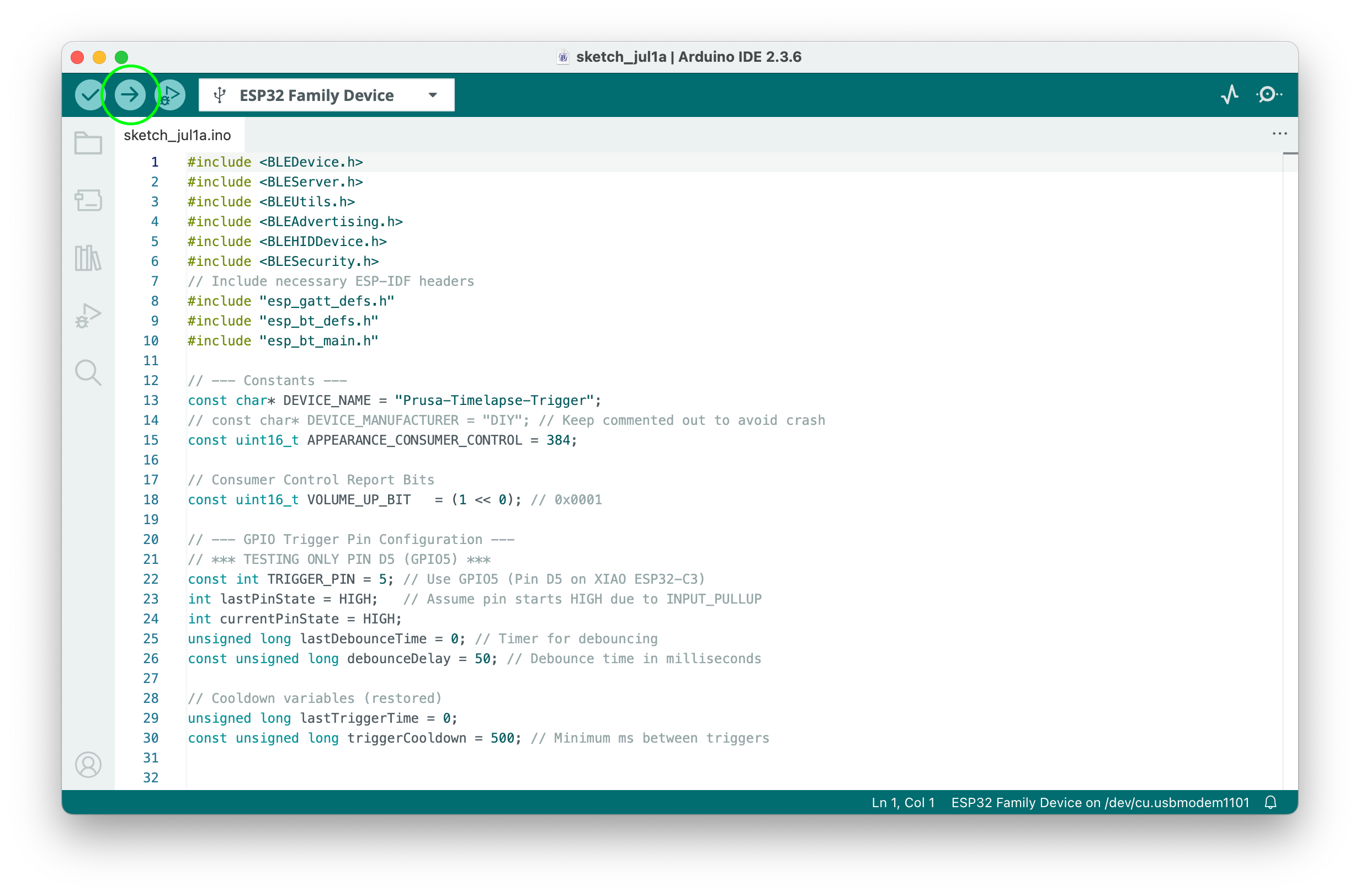
Now, you can upload the code to your ESP32. Delete the generated code in the Arduino IDE and paste the code from above. Hit the Upload button (arrow), and wait for the Arduino IDE to compile and upload the code to the board.
If everything is done correctly, try to search for the Bluetooth device named “Prusa-Timelapse-Trigger” (or a different name, if you’ve changed it in the code) and connect to it. To check for status messages in the serial communication, go to Tools -> Serial Monitor.
You can now test the trigger by simulating the signal from the Hackerboard. Use tweezers or a small wire to briefly connect the ESP32’s input pin (D3/GPIO5) to a GND pin. You should see the volume level on your phone change. If it does, you’re good to go. Disconnect the ESP32 from your computer and power it up with a standard USB-C power adapter. Now you can connect the GPIO Hackerboard to your printer. Don’t forget to turn off the printer before connecting the Hackerboard!
We have to slightly modify the G-code in PrusaSlicer, so it triggers the OUT7 instead of OUT0 output. We’ll do this by simply changing the P0 to P7 in the Start G-code and After layer change G-code sections. Now, when you start the print, each time a layer change occurs, the GPIO Hackerboard will signal the ESP32, which then sends a command to change the volume on your phone. If your camera app is active, this will trigger the shutter and take a photo.
And that’s it! This is just one of many possible use cases for the GPIO Hackerboard. Feel free to modify and improve these solutions. We look forward to seeing your ideas on how to use this small and clever module. Detailed instructions for the GPIO board can be found on our help.
Happy printing!
Hey, Prusa, here's a heads-up that some of the previous article contents on the help page for the GPIO board got lost in most languages (all except Polish) when you upgraded the site earlier this year. You can compare what's on there now with what's saved on the Wayback Machine: https://web.archive.org/web/20250115150956/https://help.prusa3d.com/article/gpio-module_734695
Among other things, the instructions for how to use inputs to trigger GCODE macros on the USB-stick are gone. Hopefully you can restore the article contents soon!
I would just like to add that I have an entire playlist dedicated to time-lapse videos, where I demonstrate the Prusa GPIO Hackerboard in combination with a wired trigger, a wireless Bluetooth trigger, and a wireless infrared trigger.
https://mzzs.link/prusa-gpio-timelapse-youtube-playlist
I would just like to add that I have an entire playlist dedicated to time-lapse videos, where I demonstrate the Prusa GPIO Hackerboard in combination with a wired trigger, a wireless Bluetooth trigger, and a wireless infrared trigger.
https://mzzs.link/prusa-gpio-timelapse-youtube-playlist
For converting the folder of pictures to a video, if you already use (or want to use) Blender, a quick search on YouTube found this tutorial video:
https://www.youtube.com/watch?v=pwYs3I3CISU
I haven't attempted to follow along with the video using the latest version of Blender yet, but it appears to be good. (The presenter seems to do a good job describing what and why he is doing each step.)
Thank you for the useful information. I had been searching for this data for about two weeks, but I got lucky here.
https://tequila.ink/
This sounds really exciting! I love how Prusa printers are so open to user modifications, and the GPIO Hackerboard clearly extends those possibilities. https://bestmousetester.com/